Table of Contents
Advertisement
Quick Links
© Copyright 2004-2007
EVERTZ MICROSYSTEMS LTD.
5288 John Lucas Drive,
Burlington, Ontario,
Canada,
L7L 5Z9
Phone:
905-335-3700
Sales Fax:
905-335-3573
Service Fax:
905-335-0909
Internet:
Sales:
Tech Support: service@evertz.com
Web Page:
Version 1.3 May 2007
The material contained in this manual consists of information that is the property of Evertz Microsystems and is
intended solely for the use of purchasers of the 2430GDAC GLink D to A Converter. Evertz Microsystems expressly
prohibits the use of this manual for any purpose other than the operation of the Downconverter.
All rights reserved. No part of this publication may be reproduced without the express written permission of Evertz
Microsystems Ltd.
Copies of this guide can be ordered from your Evertz products dealer or from Evertz
Microsystems.
Model 2430GDAC
GLink D to A Converter
Instruction Manual
sales@evertz.com
http://www.evertz.com
Advertisement
Table of Contents

Subscribe to Our Youtube Channel
Related Manuals for evertz 2430GDAC


Summary of Contents for evertz 2430GDAC
- Page 1 The material contained in this manual consists of information that is the property of Evertz Microsystems and is intended solely for the use of purchasers of the 2430GDAC GLink D to A Converter. Evertz Microsystems expressly prohibits the use of this manual for any purpose other than the operation of the Downconverter.
- Page 2 WARNING Changes or Modifications not expressly approved by Evertz Microsystems Ltd. could void the user’s authority to operate the equipment. Use of unshielded plugs or cables may cause radiation interference. Properly shielded interface cables...
- Page 3 May 07 Information contained in this manual is believed to be accurate and reliable. However, Evertz assumes no responsibility for the use thereof nor for the rights of third parties, which may be effected in any way by the use thereof. Any representations in this document concerning performance of Evertz products are for informational use only and are not warranties of future performance, either express or implied.
- Page 4 2430GDAC GLink D to A Converter This page left intentionally blank Revision 1.3...
-
Page 5: Table Of Contents
2430GDAC GLink D to A Converter TABLE OF CONTENTS OVERVIEW............................1 INSTALLATION..........................2 2.1. POWER ............................. 2 2.2. GLINK IN AND OUT ........................2 2.3. VIDEO OUT ..........................3 2.4. FIRMWARE UPGRADE PORT ....................3 2.5. CARE AND HANDLING OF OPTICAL FIBER................4 2.5.1. - Page 6 6.2.3. Part 3 – Uploading the New Firmware ................9 6.2.4. Part 4 – Completing the Upgrade................... 9 Figures Figure 1-1: 2430GDAC Block Diagram ....................... 1 Figure 2-1: 2430GDAC Module Connections ..................... 2 Tables Table 2-1: DVI-I Output Connector ........................3 Table 2-2: COM Port Pinout ..........................
-
Page 7: Overview
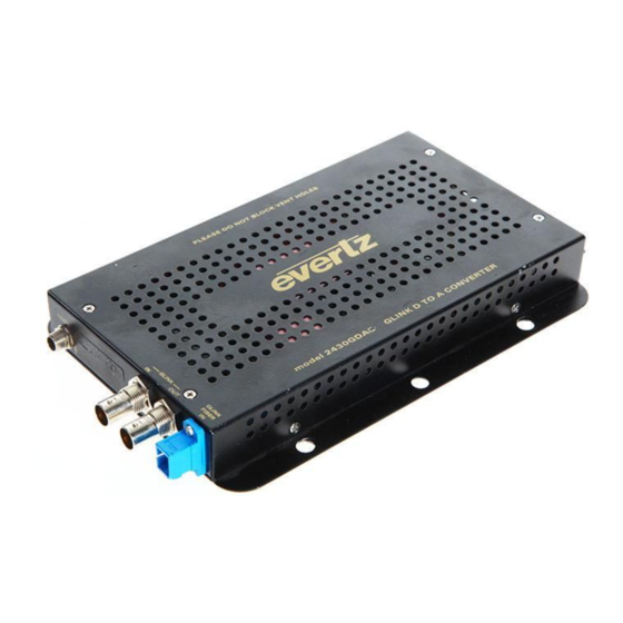
2430GDAC GLink D to A Converter OVERVIEW The 2430GDAC GLink D to A Converter provides a simple extension to Evertz MVP monitoring systems by converting GLink video signals from coaxial cable or fiber optic cable into a digital DVI signal and an analog RGB signal that can be displayed on a computer monitor or flat panel screen. -
Page 8: Installation
2430GDAC GLink D to A Converter INSTALLATION The 2430GDAC is a compact module that has two BNC connectors, one fiber optic connector, one DVI-I connector for video, and one DB-9 serial port connector for upgrades. Figure 2-1: 2430GDAC Module Connections 2.1. -
Page 9: Video Out
2.4. FIRMWARE UPGRADE PORT Serial port connector for upgrading the 2430GDAC firmware. This is a female 9 pin D connector used for connecting to a standard computer serial port. Table 2-2 shows the pinout of the female DB-9 connector. See section 5 for information on upgrading the firmware in the 2430GDAC. -
Page 10: Care And Handling Of Optical Fiber
Never look directly into an optical fiber. Non-reversible damage to the eye can occur in a matter of milliseconds. The laser modules used in the Evertz 3000MVP modules are Class I, with a maximum output power of 7mW, and a wavelength of 1270 to 1610nm. -
Page 11: Specifications
2430GDAC GLink D to A Converter SPECIFICATIONS 3.1. COAXIAL GLINK INPUT Connector: Equalization: Automatic up to 10m 3.2. FIBER GLINK INPUT Connector: SC/PC, ST/PC, or FC/PC female housing Maximum Input Power: -3dBm Wavelength: 1310 nm to 1610nm Optical Sensitivity: -23dBm Fiber Size: 62µm core / 125µm overall... -
Page 12: Physical
STATUS LED’S The locations of the status indicators are shown in Figure 2-1. POWER: Indicates that the 2430GDAC is receiving electrical power. FAULT: When on, indicates that the input GLink signal (either coaxial or fiber) is not being received. 2430GDAC - 6... -
Page 13: User Controls
USER CONTROLS The 2430GDAC has a 4 position DIP switch that is used to configure several features. The On position is down or closest to side of the unit with the flanges. Table 5-1 gives an overview of the DIP switch functions. -
Page 14: Upgrading The Firmware
Flow Control None 4. Apply power to the 2430GDAC. After the unit powers up, a banner with the boot code version information should appear in the terminal window. The cursor to the right of the word “BOOT>” should be spinning for about 5 seconds then the unit will continue to boot. -
Page 15: Part 3 - Uploading The New Firmware
11. Upload the “*.bin” file supplied using the X-Modem transfer protocol of your terminal program. If you do not start the upload within 10 minutes the 2430GDAC boot code will time out. You can restart the upgrade process by cycling the power to the unit.
Need help?
Do you have a question about the 2430GDAC and is the answer not in the manual?
Questions and answers