Table of Contents
Advertisement
Quick Links
1.
OVERVIEW......................................................................................................................................... 1
2.
INSTALLATION.................................................................................................................................. 3
3.
SPECIFICATIONS.............................................................................................................................. 5
3.1. RF INPUT/OUTPUT................................................................................................................... 5
3.2. PHYSICAL ................................................................................................................................. 5
Figures
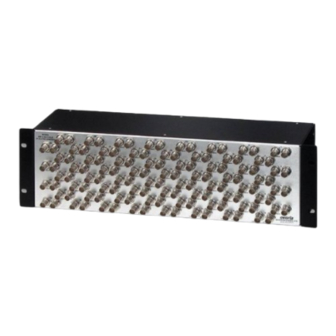
Figure 1: Front View of SRF3-64-1x2 chassis .................................................................................................... 1
Figure 2: Rear View of SRF3-64-1x2 chassis..................................................................................................... 1
Figure 3: 1x2 Splitter / 2x1 Combiner................................................................................................................. 2
Figure 4: 1x4 Splitter / 4x1 Combiner.................................................................................................................. 2
Figure 5: 128x128 L band matrix using XRF6 64x64 routers and SRF3-64-1x2 modules................................. 3
Figure 6: Front Panel of SRF3-64-1x2 chassis................................................................................................... 4
Figure 7: Rear Panel of SRF3-64-1x2 chassis ................................................................................................... 4
TABLE OF CONTENTS
....................................................................................................................... 2
.................................................................................................. 3
Revision 0.1
SRF Series RF Splitters and Combiners
Advertisement
Table of Contents

Subscribe to Our Youtube Channel
Related Manuals for evertz SRF Series


Summary of Contents for evertz SRF Series
-
Page 1: Table Of Contents
SRF Series RF Splitters and Combiners TABLE OF CONTENTS OVERVIEW............................1 1.1. B ........................2 LOCK IAGRAMS 1.2. T ....................3 YPICAL PPLICATION IAGRAM INSTALLATION..........................3 SPECIFICATIONS..........................5 3.1. RF INPUT/OUTPUT........................5 3.2. PHYSICAL ..........................5 Figures Figure 1: Front View of SRF3-64-1x2 chassis ....................1 Figure 2: Rear View of SRF3-64-1x2 chassis..................... - Page 2 Jul7 07 Information contained in this manual is believed to be accurate and reliable. However, Evertz assumes no responsibility for the use thereof nor for the rights of third parties, which may be effected in any way by the use thereof. Any representations in this document concerning performance of Evertz products are for informational use only and are not warranties of future performance, either express or implied.
-
Page 3: Overview
They can be used for signal distribution in a RF facility, or used to expand the matrix size of Evertz Microsystems XRF1 ( 16x16 ) and XRF6 ( 64x64 ) RF routers. -
Page 4: Block Diagrams
SRF Series Splitters and Combiners 1.1. BLOCK DIAGRAMS PORT A COMMON -20dB PORT B pass iv e MONITOR Figure 3: 1x2 Splitter / 2x1 Combiner PORT A PORT B COMMON -20dB pas sive PORT C MONIT OR PORT D Figure 4: 1x4 Splitter / 4x1 Combiner SRF-2 Revision 0.1... -
Page 5: Typical Application Diagram
Terminate this port with a 75 Ohm load when not connected. Please note all unused outputs on a channel ( including monitoring outputs ) must be terminated with a 75 Ohm load if they are not connected. Please contact Evertz Microsystems for recommended termination suppliers. -
Page 6: Figure 6: Front Panel Of Srf3-64-1X2 Chassis
SRF Series Splitters and Combiners Figure 6: Front Panel of SRF3-64-1x2 chassis Figure 7: Rear Panel of SRF3-64-1x2 chassis SRF-4 Revision 0.1... -
Page 7: Specifications
SRF Series Splitters and Combiners SPECIFICATIONS 3.1. RF INPUT/OUTPUT Inputs: 16 ( SRF1-16-1x2 ) 8 ( SRF1-8-1x4 ) 64 ( SRF3-64-1x2 ) 32 ( SRF3-32-1x4 ) Outputs: 32 ( SRF1-16-1x2 ) 32 ( SRF1-8-1x4 ) 128 ( SRF3-64-1x2 ) 128 ( SRF3-32-1x4 ) - Page 9 SRF Series Splitters and Combiners This page left intentionally blank SRF-1 Revision 0.1...
Need help?
Do you have a question about the SRF Series and is the answer not in the manual?
Questions and answers