Table of Contents
Advertisement
Quick Links
© Copyright 2014
EVERTZ MICROSYSTEMS LTD.
5288 John Lucas Drive,
Burlington, Ontario,
Canada L7L 5Z9
Phone:
+1 905-335-3700
Sales:
sales@evertz.com
Tech Support: service@evertz.com
Web Page:
http://www.evertz.com
Version 1.0, March 2014
The material contained in this manual consists of information that is the property of Evertz Microsystems and is intended solely for
the use of purchasers of the 2431RX-2 Series products. Evertz Microsystems expressly prohibits the use of this manual for any
purpose other than the operation of the device. Due to ongoing research and development, features and specifications in this
manual are subject to change without notice.
All rights reserved. No part of this publication may be reproduced without the express written permission of Evertz Microsystems
Ltd. Copies of this manual can be ordered from your Evertz dealer or from Evertz Microsystems.
Dual Path Serial Digital to DVI Converter
Instruction Manual
Fax: +1 905-335-3573
Fax: +1 905-335-7571
2431RX-2
Advertisement
Table of Contents

Related Manuals for evertz 2431RX-2


Summary of Contents for evertz 2431RX-2
- Page 1 Version 1.0, March 2014 The material contained in this manual consists of information that is the property of Evertz Microsystems and is intended solely for the use of purchasers of the 2431RX-2 Series products. Evertz Microsystems expressly prohibits the use of this manual for any purpose other than the operation of the device.
- Page 2 This page left intentionally blank...
- Page 3 WARNING Changes or Modifications not expressly approved by Evertz Microsystems Ltd. could void the user’s authority to operate the equipment. Use of unshielded plugs or cables may cause radiation interference. Properly shielded interface cables...
- Page 4 This page left intentionally blank...
- Page 5 Any representations in this document concerning performance of Evertz products are for informational use only and are not warranties of future performance, either expressed or implied. The only warranty offered by Evertz in relation to this product is the Evertz standard limited warranty, stated in the sales contract or order confirmation form.
- Page 6 2431RX-2 Dual Path Serial Digital to DVI Converter This page left intentionally blank Page ii Revision 1.0...
-
Page 7: Table Of Contents
2431RX-2 Dual Path Serial Digital to DVI Converter TABLE OF CONTENTS OVERVIEW ........................... 1 SPECIFICATIONS ......................... 3 2.1. SERIAL INPUTS ........................3 2.2. OPTICAL INPUT ........................3 2.3. DVI OUTPUTS ........................3 2.4. ANALOG AUDIO OUTPUT ....................3 2.5. ELECTRICAL ........................3 2.6. - Page 8 5.1.2. Part 2 – Terminal Program Setup ................39 5.1.3. Part 3 – Uploading the New Firmware ..............40 5.1.4. Part 4 – Completing the Upgrade ................40 5.2. FTP UPGRADE METHOD ....................41 2431RX-2 CONFIGURATION USING VISTALINK PRO ............. 43 ® 6.1. SNMP V1 ..........................43 6.2.
- Page 9 Figure 1-1: 2431RX-2 Block Diagram ....................... 2 Figure 3-1: 2431RX-2 Rear View ........................5 Figure 3-2: 2431RX-2 Rear View – DVI-I Connectors ..................6 Figure 3-3: 2431RX-2 Rear View – BNC Connectors ..................6 Figure 3-4: 2431RX-2 Rear View – Fiber Connectors ..................6 Figure 3-5: 2431RX-2 Front View –...
- Page 10 Figure 6-1: Configuring VistaLINK PRO ....................... 43 ® Figure 6-2: Configuration Page for 2431RX-2 ....................44 Figure 6-3: Server SNMP Communications User ................... 45 Figure 6-4: Add an SNMP Name for the SNMP V3 Role ................45 Figure 6-5: Add Authentication Password ...................... 46 Figure 6-6: Edit Username ..........................
-
Page 11: Overview
The 2431RX-2 is a versatile dual path serial digital to DVI converter. The 2431RX-2 is used for projects where high density extension of DVI over coax or fiber is required. 2431RX-2 is used as part of the EFX system for video wall and command center projects. This self-contained module accepts up to two serial inputs over coax or fiber (with additional SFP) and converts them to single link or dual link DVI with a resolution range of up to WQXGA (2560x1600). -
Page 12: Figure 1-1: 2431Rx-2 Block Diagram
CH 1&2 AES CH2 Analog out EMBEDDERS or CH 1&2 AES 2 x 3G/1.5G Optical SFP SFP OPTION CONTROL / MONITORING 2 x 3G/1.5G Optical SFP SFP OPTION SERAIL Figure 1-1: 2431RX-2 Block Diagram Page - 2 OVERVIEW Revision 1.0... -
Page 13: Specifications
Dual Path Serial Digital to DVI Converter SPECIFICATIONS 2.1. SERIAL INPUTS Standard: SMPTE 259M, 292M, 424M and Evertz proprietary format (3Gbps/1.5Gbps) Number of Inputs: 2 - total 4BNCs when in dual link reception mode Connector: BNC per IEC 60 169-8 Amendment 2... -
Page 14: Physical
2431RX-2 Dual Path Serial Digital to DVI Converter 2.6. PHYSICAL Dimensions with mounting flanges: 7.81” L x 5.63” W x 1.75” H (199mm L x 143mm W x 45mm H) Weight: 1 lbs. (0.45 kg) 2.7. COMPLIANCE Electrical Safety: Power supply UL listed... -
Page 15: Installation
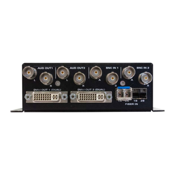
Dual Path Serial Digital to DVI Converter INSTALLATION The 2431RX-2 is a compact module that has four BNC connectors for serial digital input, four BNC connectors for analog audio output (BNC to RCA connector included), 4 fiber optic connectors (2 per SFP), two DVI-I connectors for video outputs, one DB-9 serial port connector for settings and one Ethernet connector for control and monitoring. -
Page 16: Bnc Connectors
2431RX-2 Dual Path Serial Digital to DVI Converter Figure 3-2: 2431RX-2 Rear View – DVI-I Connectors 3.3. BNC CONNECTORS BNC connectors are used for serial digital inputs (4 BNC connectors) and analog audio output (4 BNC connectors). Figure 3-3: 2431RX-2 Rear View – BNC Connectors 3.4. -
Page 17: Db9 Connector
DB-9 connector. Pin # Name Description RS-232 Transmit Output RS-232 Receive Input Sig Gnd RS-232 Signal Ground Table 2-2: DB9 Port Pin Out Figure 3-5: 2431RX-2 Front View – DB9 Connector INSTALLATION Page - 7 Revision 1.0... -
Page 18: Care And Handling Of Optical Fiber
Never look directly into an optical fiber. Non-reversible damage to the eye can occur in a matter of milliseconds. The laser modules used in the Evertz 3000MVP modules are Class I, with a maximum output power of 7mW, and a wavelength of 1310 to 1610nm. -
Page 19: Status Leds
When On this LED indicates that unit is booting (5 sec) or unit has malfunction. Indicates that the 2431RX-2 is receiving video input on BNC or Fiber 1A. Indicates that the 2431RX-2 is receiving video input on BNC or Fiber 2A. -
Page 20: User Controls
2431RX-2 Dual Path Serial Digital to DVI Converter 3.8. USER CONTROLS 3.8.1. Dip Switches Figure 3-7: 2431RX-2 DIP Switches DIP Switch Function Enable deinterlacer for input 1 Enable deinterlacer for input 2 For future use For future use For future use... -
Page 21: Configuration
Table 4-1: Serial Port Terminal Settings 4.2. SERIAL MENU Configure your terminal program to the table settings in Table 4-2 and press the <enter> button. The session should respond with the 2431RX-2 Main Menu. Figure 4-1: 2431RX-2 Serial Menu CONFIGURATION Page - 11... -
Page 22: Network Configuration
2431RX-2 Dual Path Serial Digital to DVI Converter 4.2.1. Network Configuration This sub-menu enables the user to configure the network settings for the card. Figure 4-2: Network Configuration 1. Select option (1) Set IP Address and configure the IP address for the Unit ensuring that the IP address is not already in use on the network. -
Page 23: Video Utilities Menu
2431RX-2 Dual Path Serial Digital to DVI Converter 4.2.3. Video Utilities Menu This menu has multiple sub menus for Video Standard Information, Lock Video Input Mode, decimation settings, set output color on signal loss, enable/ disable interlace output format, enable/disable agile locking and display EDID information. -
Page 24: Lock Video Input Mode
4.2.3.3. YCBCR Decimation Settings This menu allows the user to change YCBCR decimation, it applies only when signal type is RGBR. Figure 4-7: YCBCR Decimation Settings Note: Setting must not be used without Evertz technical guidance Page - 14 CONFIGURATION Revision 1.0... -
Page 25: Set Output Color On Signal Loss
4.2.3.5. Enable Deinterlacing This menu allows the user to turn the deinterlacer on or off on a per channel basis. When deinterlacer is on the 2431RX-2 will output a progressive signal, when deinterlacer is off the 2431RX-2 will output an interlaced signal. -
Page 26: Enable Agile Locking
2. Disable (will be prompted for input 1 or 2) Figure 4-10: Enable Agile Locking Note: Setting must not be used without Evertz technical guidance. 4.2.3.7. ANX9806 Status Check This Option is for Evertz Personnel Only. Page - 16 CONFIGURATION Revision 1.0... -
Page 27: Get Edid
2431RX-2 Dual Path Serial Digital to DVI Converter 4.2.3.8. Get EDID This menu allows the user the option to retrieve EDID information of the monitor connected to input. The user can retrieve EDID information for both the outpust by choosing output 1 or 2. -
Page 28: Figure 4-13: Print Vproc Ctrl Numbers
2431RX-2 Dual Path Serial Digital to DVI Converter 1. Print VPROC CTRL Numbers (Output 1 or 2): Prints out a list of all VPROC controls and current values. Figure 4-13: Print VPROC CTRL Numbers • Gain Level Controls There are eight controls that set the gain of the video. With these controls, the user can adjust the gain of the 3 components in either the Y, Cr, Cb domain or the R, G, B domain over a range of - 50% to 100% in 0.1% steps. -
Page 29: Figure 4-14: Gain Level Controls
2431RX-2 Dual Path Serial Digital to DVI Converter B Offset: Ranges from –200 to 200 quantization levels in 1 level increments. Figure 4-14: Gain Level Controls • Gamma Level With this control, the user can adjust the overall Gamma correction factor from - 128 to + 127 in increments of 1. -
Page 30: Figure 4-17: Rgb Limiter
2431RX-2 Dual Path Serial Digital to DVI Converter Figure 4-17: RGB Limiter 2. Set VPROC Value: The user can change VPROC Values by selecting Output (1 or 2), Control Index Number, and the value to be set. Figure 4-18: Set VPROC Value 3. -
Page 31: Scaler Configuration
1. Enable/Disable Scaler: Allow the user to enable/ disable scaling per path. Figure 4-21: Enable/Disable Scaler Note: Setting must not be used without Evertz technical guidance. 2. Select Scaler Mode Settings: Allows the user to select between 4 scaler modes on a per path basis. -
Page 32: Figure 4-22: Select Scaler Mode Settings
2431RX-2 Dual Path Serial Digital to DVI Converter Figure 4-22: Select Scaler Mode Settings 3. Select Scaler Output Resolution: Allows the user to selects the output resolution per path. (Enter 1 or 2 to select output path) 4. Select Scaler Crop Settings: Allows the user to crop the input per path. The user can specify Cropping by Pixel or percentage. -
Page 33: Under Monitor Display Setup
2431RX-2 Dual Path Serial Digital to DVI Converter 4.2.5. Under Monitor Display Setup: This sub Menu controls all UMD settings. UMD’s work with Image Video Protocol Only. Figure 4-24: Under Monitor Display Setup Select Display: Allows the user to select between UMD settings for Input 1-2. - Page 34 2431RX-2 Dual Path Serial Digital to DVI Converter Set Display Mode: Allows the user to choose OSD overlay mode from 3 different options. 0. Always off: Allows the user to turn off OSD’s overlay. 1. Always On: Allows the user to enable OSD overlay to always display.
- Page 35 2431RX-2 Dual Path Serial Digital to DVI Converter 9. Set UMD Colors: Allows the user to set the text color, background color and border color. Set Text Color: Allows the user to set the font color and transparency ( values in hex where...
-
Page 36: Figure 4-25: Umd Line Data
Dual Path Serial Digital to DVI Converter 10. UMD Line Data The 2431RX-2 is capable of outputting 3 separate lines of OSD Data. The user can choose what data type is displayed on each line. Figure 4-25: UMD Line Data Available Data Types: 0 –... -
Page 37: Snmp Configuration
2431RX-2 Dual Path Serial Digital to DVI Converter 4.2.6. SNMP Configuration This menu allows the user to configure SNMP V1 and V3 settings. Figure 4-26: SNMP Configuration Menu SNMP V1 Setup allows the user to configure Trap destination and Community strings (read and write) for SNMP V1. -
Page 38: Figure 4-29: Snmp V3 User Setup
2431RX-2 Dual Path Serial Digital to DVI Converter SNMP V3 User Setup allows the user to add up to 10 SNMP V3 user profiles and encryption types. Figure 4-29: SNMP V3 User Setup Add SNMP V3 USER allows creation and editing of up to 10 SNMP V3 user profiles. -
Page 39: Figure 4-31: Remove Snmp V3 User
2431RX-2 Dual Path Serial Digital to DVI Converter Remove SNMP V3 User allows the user to remove users from access the unit using SNMP V3 authentication. Figure 4-31: Remove SNMP V3 User Show All SNMP V3 User allows the user to verify which user has authentication to access the unit. -
Page 40: Figure 4-34: Add Snmp V3 Access Control
2431RX-2 Dual Path Serial Digital to DVI Converter Add/EDIT SNMP V3 Access Control allows the user to specify read/write control on a per user basis for any OID. Figure 4-34: Add SNMP V3 Access Control Remove SNMP V3 Access Control allows the user to remove access controls for a user. -
Page 41: Figure 4-36: Show All Snmp V3 Access Control
Dual Path Serial Digital to DVI Converter Show all SNMP V3 Access Control allows the user to verify all current access control settings on the 2431RX-2. Figure 4-36: Show All SNMP V3 Access Control SNMP V3 Notifications Setup allows the user to set trap destination and remove trap destination for SNMP V3. -
Page 42: Snmp Version
2431RX-2 Dual Path Serial Digital to DVI Converter Remove SNMP Notification allows the user to remove notification settings on the unit. Figure 4-39: Remove SNMP Notification 4.2.6.2. SNMP Version This menu allows the user to set the unit to communicate using SNMP V1 or V3 version. -
Page 43: Figure 4-41: Snmo Get Set Version Setup
2431RX-2 Dual Path Serial Digital to DVI Converter SNMP Get Set Version Setup allows the user to set the SNMP V1 or V3 version used for configuration and update. Figure 4-41: SNMO Get Set Version Setup SNMP Trap Version Setup allows the user to set the SNMP V1 or V3 version used to send traps. -
Page 44: Sntp Setup
2431RX-2 Dual Path Serial Digital to DVI Converter 4.2.7. SNTP Setup Figure 4-43: SNTP Setup Set NTP server address (Allows the user to specify the address of the NTP time server) Figure 4-44: Set NTP Server Address Enable Daylight savings time ( Toggles Daylight savings time settings On/Off) -
Page 45: Figure 4-45: Enable Daylight Savings Time
2431RX-2 Dual Path Serial Digital to DVI Converter Figure 4-45: Enable Daylight Savings Time Daylight saving start time (Allows the user to configure the start of DST date/time) Figure 4-46: Daylight Saving Start Time Set DST Mode (Selects between either DAY/Month or Day/Week configuration) - Page 46 2431RX-2 Dual Path Serial Digital to DVI Converter Daylight savings end time (Allows the user to configure the ending DST Date/Time) Figure 4-47: Daylight Savings End Time Set DST Mode (Selects between either DAY/Month or Day/Week configuration) SET DST Month ( Selects the start month for DST...
-
Page 47: Clock Setup
2431RX-2 Dual Path Serial Digital to DVI Converter 4.2.8. Clock Setup Set Offset (Allows the user to offset the incoming NTP time) Figure 4-48: Clock Setup - Set Offset Set offset Dir (Allows the user to toggle between a positive and negative offset mode) Figure 4-49: Clock Setup –... -
Page 48: Engineering Menu
Figure 4-51: Clock Setup – Set Date Format 4.2.9. Engineering Menu This menu is for Evertz personnel only. The user may be requested to access and execute options within this menu when seeking technical support from Evertz. Guidance will be given should this be required. -
Page 49: Upgrading Firmware
2431RX-2 Dual Path Serial Digital to DVI Converter UPGRADING FIRMWARE 5.1. UPDATE PROCEDURE 5.1.1. Part 1 – Configuring the Unit for Firmware Upgrades Connect the 9 pin male connector on the straight through serial extension cable to the COM port on the end of the 2430TX-2. -
Page 50: Part 3 - Uploading The New Firmware
2431RX-2 Dual Path Serial Digital to DVI Converter 6. The user should now see a prompt asking you to upload the file. 5.1.3. Part 3 – Uploading the New Firmware 1. Upload the “*.bin” file supplied using the X-Modem transfer protocol of your terminal program. If the upload is not started within 10 minutes the 2430TX-2 boot code will time out. -
Page 51: Ftp Upgrade Method
2431RX-2 Dual Path Serial Digital to DVI Converter 5.2. FTP UPGRADE METHOD 1. Set the IP address on the unit. 2. Connect serial port to the unit. 3. Open HyperTerminal and set the serial setting as follows: Baud 115200 Parity... - Page 52 2431RX-2 Dual Path Serial Digital to DVI Converter This page left intentionally blank Page - 42 UPGRADING FIRMWARE Revision 1.0...
-
Page 53: 31Rx-2 Configuration Using Vistalink Pro
® Login to VistaLINK Pro server. Default login is administrator with no password. ® Go to Help > apply update > product > and browse to the jar file location of 2431RX-2. Figure 6-1: Configuring VistaLINK ® VistaLINK Pro will ask you to reboot, select OK. - Page 54 2431RX-2 Dual Path Serial Digital to DVI Converter Figure 6-2: Configuration Page for 2431RX-2 Page - 44 VISTALINK Revision 1.0 ®...
-
Page 55: Configuring Vlpro For Snmp V3
2431RX-2 Dual Path Serial Digital to DVI Converter 6.2. CONFIGURING VLPRO FOR SNMP V3 Launch VistaLINK PRO Server and Client. ® Go to tools > User a menu will appear. Figure 6-3: Server SNMP Communications User Make sure Server SNMP Communications user is set to current User. (See Figure 6-3) Click the add button and another context menu will appear. - Page 56 Click the Add button to add a new device. Enter IP of the unit, and select password encryption type. MD5 or SHA-1. Enter the username specified on the 2431RX-2 unit for authentication. Add the authentication password (if any) and the encryption password (if any) in the dialog box.
- Page 57 Navigate to the User’s SNMP V3 TAB and add a checkmark to the desired SNMP V3 Group(s) for authentication. Figure 6-7: SNMP V3 Group(s) Authentication 12. Click OK to save. 13. Reboot VistaLINK Pro Client and Server. ® 14. The 2431RX-2 will now be configured with SNMP V3. VISTALINK Page - 47 Revision 1.0 ®...
-
Page 58: 2431Rx-2 Vistalink
6.3. 2431RX-2 VISTALINK CONFIGURATION VIEW ® Configure 2431RX-2 with VistaLINK Pro, right click on the IP address of 2431RX-2. Select View ® Configuration form the popup menu that appears, as shown in below. Figure 6-8: Configure 2431RX-2 with VistaLINK ®... -
Page 59: General Tab
2431RX-2 Dual Path Serial Digital to DVI Converter Once View Configuration is selected the user will be presented with the main configuration screen as shown below: Figure 6-9: Main configuration Screen 6.3.1. General Tab The General tab shows generic system information including card type, serial number, software version information and device FPGA temperatures. -
Page 60: Input Monitoring
2431RX-2 Dual Path Serial Digital to DVI Converter 6.3.2. Input Monitoring This tab allows the user to view information on the incoming signal including resolution, frame rate, signal format, source input (coaxial or fiber), Incoming signal HDCP encryption status, signal power for fiber input, and audio presence. -
Page 61: Input Controls
2431RX-2 Dual Path Serial Digital to DVI Converter 6.3.3. Input Controls Input controls tab allows the user to: • Lock incoming format to 3G-SDI or 3G-Gink, GLink, KVM, or Auto detect. • Enable/Disable agile locking. • Enable/Disable video de-interlacing. •... -
Page 62: Output Controls
2431RX-2 Dual Path Serial Digital to DVI Converter 6.3.5. Output Controls Output controls tab allows the user to change the output functionalities of the 2431RX-2. Figure 6-14: Output Controls Output control tab contains: • Enable/Disable output scaler on a per channel basis. (Unit will reboot when change is made) •... -
Page 63: Video Processing Tab
2431RX-2 Dual Path Serial Digital to DVI Converter 6.3.6. Video Processing Tab This video processing tab allows the user to apply colour correction to each individual output. An advanced set of processing controls provides the user with substantial control to fine tune the output displays. -
Page 64: Umd Output Controls
2431RX-2 Dual Path Serial Digital to DVI Converter 6.3.7. UMD Output Controls This tab allows the user to configure the 2431RX-2’s OSD settings. Figure 6-16: UMD Output Controls Settings include: • Protocol ID’s per display. • Display mode of UMD. -
Page 65: Sntp Controls
2431RX-2 Dual Path Serial Digital to DVI Converter 6.3.8. SNTP Controls This menu allows the user to change NTP clock IP, clock offsets, configure Daylight Savings Time (DST) settings, and change clock and date formats. Figure 6-17: SNTP Controls VISTALINK Page - 55 Revision 1.0... -
Page 66: Faults Tab
2431RX-2 Dual Path Serial Digital to DVI Converter 6.3.9. Faults Tab This tab allows the user to view fault presence and configure fault trap setting for the 2431RX-2. The user can monitor the following faults • Fan error If fan is disconnected or stops spinning the fault will trigger.
Need help?
Do you have a question about the 2431RX-2 and is the answer not in the manual?
Questions and answers