Table of Contents
Advertisement
Quick Links
Advertisement
Table of Contents

Related Manuals for Pepperl+Fuchs R2-SP-IC Series


Summary of Contents for Pepperl+Fuchs R2-SP-IC Series
- Page 1 PROCESS AUTOMATION MANUAL Segment Protector R2-SP-IC*...
- Page 2 Segment Protector With regard to the supply of products, the current issue of the following document is ap- plicable: The General Terms of Delivery for Products and Services of the Electrical Indus- try, published by the Central Association of the Electrical Industry (Zentralverband Elektrotechnik und Elektroindustrie (ZVEI) e.V.) in its most recent version as well as the supplementary clause: "Expanded reservation of proprietorship"...
-
Page 3: Table Of Contents
Segment Protector Introduction................. 5 Contents....................5 Target Group, Personnel..............5 Symbols Used ..................5 Product Specifications............... 7 Overview and Application ..............7 Component Identity ................9 Technical Data R2-SP-IC* ..............9 Hazardous Area Installation and Use ........12 Installation in Zone 2, no Live Maintenance at Trunk and Spurs (Ex nAc) .................... - Page 4 Segment Protector Fault Detection, Physical Layer Diagnostics ........24 5.2.1 Device Signal Level ................24 5.2.2 Device Signal Jitter................25 Fault Isolation ..................25 5.3.1 Short Circuit Current Limitation (Static Fault Protection) ....25 5.3.2 Spur Contact Bounce Protection (Dynamic Fault Protection) ... 25 5.3.3 Progressive Spur Short Circuit Current Limitation (Creeping Fault Protection) ................
-
Page 5: Introduction
Segment Protector Introduction Introduction Contents This document contains information that you need in order to use your product throughout the applicable stages of the product life cycle. These can include the following: Product identification ■ Delivery, transport, and storage ■ Mounting and installation ■... - Page 6 Segment Protector Introduction Warning Messages You will find warning messages in instances, whenever dangers may arise from your actions. It is mandatory that you observe these warning messages for your personal safety and in order to avoid property damages. Depending on the risk level, the warning messages are displayed in descending order as follows: Danger! This symbol indicates an imminent danger.
-
Page 7: Product Specifications
Type of protection The Segment Protector is certified for installation in Zone 2. Using Pepperl+Fuchs Segment Protectors in combination with Pepperl+Fuchs fieldbus power supplies allows you to perform live maintenance at the field device level in Zone 2 because the outputs are either classified Entity Ex ic or FISCO ic. - Page 8 Pepperl+Fuchs advanced physical layer Infrastructure, enabling the maintenance engineer to change defective units before they start to adversely influence fieldbus communication. Being an integral part of the segment, the Pepperl+Fuchs advanced physical layer infrastructure does not require any scheduled manual maintenance activity.
-
Page 9: Component Identity
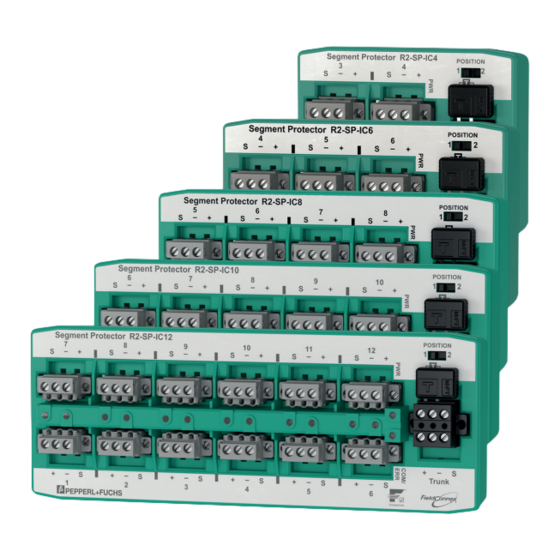
Segment Protector Product Specifications Component Identity POSITION Trunk Segment Protector ® 37 (1.5") 42 (1.7") 60 (2.4") Height see table "Technical Data Depending on Model" on page 11 Spur 1 connector LED ERR Spur 1 (red, short circuit) LED COM/ERR (communication/diagnostics) LED PWR (power) Separation wall ACC-R2-SW.3 Switch, short circuit current selection... - Page 10 Segment Protector Product Specifications Technical Data Voltage drop main max. 1.2 V cable/outputs Voltage drop trunk In/Out Terminating resistor external type M-FT 100 +/- 10 % Surge protection Trunk overvoltage protection if voltage exceeds typ. 39 V, max. 41 V Indicators/operating means Switch configuration of short-circuit current/rated current...
- Page 11 Segment Protector Product Specifications Technical Data Current 46 mA switch 1, position 1 65 mA switch 1, position 2 Inductance 0.125 mH switch 1, position 1 0.25 mH switch 1, position 2 Capacitance 60 nF Directive conformity Directive 94/9/EC EN 60079-0:2009 , EN 60079-11:2012 , EN 60079-15:2010 International approvals...
-
Page 12: Hazardous Area Installation And Use
For the requirements for typical fieldbus products for use in Zone 2 installations refer to the manual: ‘Using Pepperl+Fuchs fieldbus equipment in Zone 2 hazardous area environment’. This document is supplied separately and can be obtained from the Pepperl+Fuchs Internet product database. -
Page 13: Spur Voltage Limited By The External Fieldbus Power Supply Uo 24V, Entity Examination
Requirements for typical fieldbus products for use in Zone 2 installations are summarized in the manual: ‘Using Pepperl+Fuchs fieldbus equipment in Zone 2 hazardous area environment. This document is supplied separately and can be obtained from Pepperl+Fuchs Internet product database. -
Page 14: Spur Voltage Limited By The External Fieldbus Power Supply, Fisco Examination
The requirements for typical fieldbus products for use in Zone 2 installations are summarized in the manual: ‘Using Pepperl+Fuchs fieldbus equipment in Zone 2 hazardous area environment’. This document is supplied separately and can be obtained from Pepperl+Fuchs Internet product data base. -
Page 15: Installation And Commissioning
Segment Protector Installation and Commissioning Installation and Commissioning In the following section you find information on how to install and commission the device in your fieldbus topology. Danger! Risk of explosion through exposition to gas atmosphere If the device is installed in Zone 2 without mounting it in a sufficiently suitable enclosure, dust, water or other external interferences can cause the live device to spark. - Page 16 Segment Protector Installation and Commissioning Mounting the Segment Protector on a DIN Mounting Rail 1. Place the Segment Protector on the DIN mounting rail. 2. Gently press the Segment Protector to the DIN mounting rail until it is locked in place. The Segment Protector clicks into place.
-
Page 17: Separation Wall To Provide Intrinsic Safety (Ex Ic)
4.1.1 Separation Wall to Provide Intrinsic Safety (Ex ic) To generate Ex ic rated spur outputs for Pepperl+Fuchs Segment Protectors in combination with Fieldbus Power Supplies, a separation wall must be positioned inside the Segment Protector. The separation wall is available as accessory. The separation wall is a mandatory prerequisite to ensure the required clearance of 50 mm between the trunk terminals and the spur terminals. -
Page 18: Additional Information On Vertical Mounting
If a Segment Protector is mounted vertically, use end brackets / end clamps on both sides of the Segment Protector to prevent shifting of the device. Pepperl+Fuchs recommends using the following Phoenix Contact parts: Clipfix 35, snap-on end bracket, PHOENIX CONTACT part no: 3022218 ■... -
Page 19: Segment Protector Connection Layout Of The Trunk
Segment Protector Installation and Commissioning Segment Protector Connection Layout of the Trunk Danger! Risk of explosion through exposed conductors Exposed conductors of inadequately fixed cables can cause sparks that can ignite the surrounding atmosphere. When installing the device ensure that the cables are securely fixed. Danger! Risk of connection damage and resulting increased explosion hazard Manipulating connections outside of the specified ambient temperature range can lead to... -
Page 20: Segment Protector Connection Layout Of The Spurs
Segment Protector Installation and Commissioning Ensure that connectors are mechanically locked ■ Torque required for tightening terminal screws: 0.4-0.5 Nm ■ Spring Terminals: Cable and Connection Information Permissible wire core section: ■ - Spring terminals with flexible or rigid wires: 0.5-2.5 mm² Insulation stripping length: 10 mm ■... -
Page 21: Grounding / Shielding Of Fieldbus Transmission Lines
Segment Protector Installation and Commissioning Screw Terminals: Cable and Connection Information Permissible wire core section: ■ - Screw terminals with flexible or rigid wires: 0.2-2.5 mm² Insulation stripping length: 7 mm ■ If you use stranded connectors: Crimp on wire end ferrules ■... -
Page 22: Series Connection And Termination
Segment Protector Installation and Commissioning Series Connection and Termination In order to connect several Segment Protectors in series, loop the trunk line through the T- connector. For exchange or maintenance of a Segment Protector within a series connection, pull off the respective T-connector without loosening the trunk lines. - Page 23 Segment Protector Installation and Commissioning Terminating a Spring Trunk Terminal 1. Plug in the M-FT terminator using the 2 entries shown in the picture. 2. Push down the M-FT. 3. Ensure that the M-FT is fully plugged in as shown. In order to remove the M-FT, proceed as follows: Use a tool, e.g., a screw driver, to press down the 2 springs of the terminal shown in the picture.
-
Page 24: Operation
After a fault or deviation has been detected, a single yellow LED serves as fault indicator at the respective device coupler. For more information see chapter 5.1 Using Pepperl+Fuchs “Advanced Physical Layer” solutions, e. g., the diagnostic module HD2- DM-A, show the diagnostic state of the individual device in the specific working environment of the process control system. -
Page 25: Device Signal Jitter
This could cause a temporary or total loss of communication, even leading to the loss of the segment. The Pepperl+Fuchs Spur Contact Bounce Protection isolates a faulty spur from the segment to prevent segment failures caused by intermittent faults that are not detected by conventional spur protection device couplers. -
Page 26: Device Jabber Protection
Inhibit’ circuit or ‘watchdog’. Up to this point, not all currently available devices support or contain the ‘jabber inhibit’ ‘watchdog’. The Pepperl+Fuchs device couplers have a spur dependent ‘jabber inhibit’ feature to isolate a faulty field device from the segment in such events. -
Page 27: Accessory: Enclosure Leakage Sensor Els-1
IEC 60079–11. As an associated apparatus, ELS–1 can be attached to any fieldbus trunk or spur that is intrinsically safe certified. ELS–1 can be connected in parallel to the spur output cables of Pepperl+Fuchs device couplers types R2-SP-IC*, F2-SP-IC*, and R4D0-FB-*. Powered by the spur, ELS–1 requires less than 6 mA for operation. -
Page 28: Using Device Couplers In Profibus Pa Installations
Increase the RETRY LIMIT parameter of the PROFIBUS master to a minimum of 4 ■ Note: When using the Pepperl+Fuchs Segment Coupler HD2-GT* series, the default value of the RETRY LIMIT is already set to 4. In order to disconnect a field device, ensure to adhere to the following sequence: ■... -
Page 29: Appendix
Segment Protector Appendix Appendix Ordering Information Product name Description R2-SP-IC-4 Segment Protector with 4 outputs (spurs). Trunk and spur connections with screw terminals. R2-SP-IC-6 Segment Protector with 6 outputs (spurs). Trunk and spur connections with screw terminals. R2-SP-IC-8 Segment Protector with 8 outputs (spurs). Trunk and spur connections with screw terminals. -
Page 30: Electromagnetic Compatibility Verification In Accordance With Ec Council Legislation Directive 2004/108/Ec
EN 55011 Reduction factor conducted emission Class A Reduction factor radiated emission Class A Referenced Documents Manual: "Using Pepperl+Fuchs fieldbus equipment in Zone 2 hazardous area ■ environment" Selection table: Conformity of FieldConnex Power Hub modules and motherboards to ®... - Page 31 Segment Protector Appendix...
- Page 32 PROCESS AUTOMATION – PROTECTING YOUR PROCESS Worldwide Headquarters Pepperl+Fuchs GmbH 68307 Mannheim · Germany Tel. +49 621 776-0 E-mail: info@de.pepperl-fuchs.com For the Pepperl+Fuchs representative closest to you check www.pepperl-fuchs.com/contact www.pepperl-fuchs.com Subject to modifications / TDOCT-2773E_ENG Copyright PEPPERL+FUCHS • Printed in Germany 08/2015...
Need help?
Do you have a question about the R2-SP-IC Series and is the answer not in the manual?
Questions and answers