Table of Contents
Advertisement
Quick Links
Advertisement
Table of Contents

Related Manuals for Pepperl+Fuchs 6000 Purge System


Summary of Contents for Pepperl+Fuchs 6000 Purge System
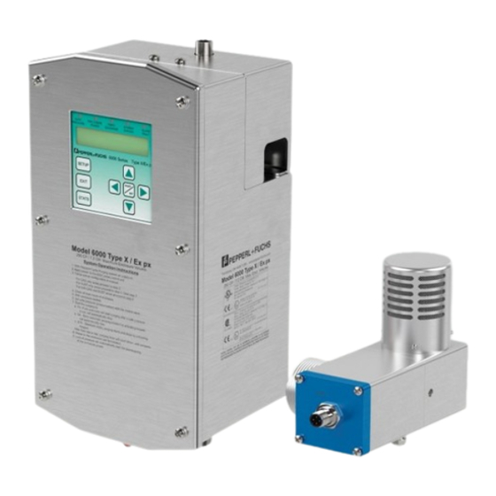
- Page 1 6000 Purge System User Manual Type X and Ex pxb Purge and Pressurization System...
- Page 2 The latest version of the General Terms of Delivery for Products and Services in the Electronics Industry set out by the German Electrical and Electronic Manufacturers’ Association (ZVEI) and the "Extended Reservation of Proprietorship" supplementary clause apply to this document.
-
Page 3: Table Of Contents
6000 S T erieS anual able of conTenTS Table of contents 1. Introduction .....................6 1.1. Content of this Document ................6 1.2. Target Group, Personnel................7 1.3. Symbols Used ....................8 1.4. Pertinent Laws, Standards, Directives, and Further Documentation ....9 1.5. - Page 4 6000 S T erieS anual able of conTenTS 2.5. 6000 Series Accessories ................40 2.5.1 6000-TEMP-01, Temperature Hub ............40 2.5.2 6000-TSEN-01, Temperature Sensor ............41 2.5.3 Additional Accessories ................42 3. Operation ....................43 3.1. Sequence of Events ..................43 3.1.1 Turning on Power to the Enclosure ............
- Page 5 6000 S T erieS anual able of conTenTS 5. Product Identification ................73 5.1. Specific Conditions of Use ................73 5.2. Applied Standards and Markings ..............75 5.3. Type Codes ....................75 5.4. Labels and Markings ................... 76 6. Lifetime Product Care ................80 6.1.
-
Page 6: Introduction
6000 S i 6000 S i erieS anual nTroducTion erieS anual nTroducTion 1. Introduction 1.1. Content of this Document This document contains information required to meet the safety and protection requirements for systems with explosion protection in equipment Group II, Zones 1 or 21, Class I/II, Division 1 when installing, commissioning, and using the 6000 control unit and its components. -
Page 7: Target Group, Personnel
i nTroducTion In addition, the documentation may comprise the following parts, if applicable: Manufacturer declaration of conformity EU declaration of conformity Control drawings Additional documents 1.2. Target group, Personnel Responsibility for planning, assembly, commissioning, operation, maintenance, and dismounting of the 6000 series lies with the plant operator. Personnel working on this system must: be familiar with the regulations about safety and accident prevention and briefed in handling of the component. -
Page 8: Symbols Used
6000 S i 6000 S i erieS anual nTroducTion erieS anual nTroducTion 1.3. Symbols Used This document contains symbols to identify warning messages and information messages. Warnings You will always find warning messages whenever hazards could result from your actions. -
Page 9: Pertinent Laws, Standards, Directives, And Further Documentation
A Declaration of Conformity is included with these instructions and can be requested from the manufacturer or obtained online at www.pepperl-fuchs.com. Additional documentation can also be provided for individual components. The product manufacturer, the Pepperl+Fuchs Group, 68307 Mannheim, has a certified quality assurance system that conforms to ISO 9001. ISO9001... -
Page 10: Product Description
2.1.1 Purpose The purpose of the Pepperl+Fuchs 6000 series Type X & Ex px, Class I/II, Division 1 / Zone 1/21 enclosure protection system is to allow the use of general purpose or non- rated electrical or electronic devices located in general purpose enclosures instead of explosionproof/flameproof, Type 7 or 9 / Ex d enclosures or other means of protection for the rated area. -
Page 11: Control Unit
6000 S P erieS anual roducT eScriPTion controller (UIC), and EPV-6000 vent are provided by the EPCU through the internal galvanically isolated intrinsic safety barrier. No additional I.S. barrier is required. The adjustable mounting bracket and the universally mountable vent make the 6000 system easy to install horizontally or vertically onto the enclosure. -
Page 12: Images
6000 S P erieS anual roducT eScriPTion 2.2.2 Images Control Unit Bracket for mounting to the enclosure I.S. wiring terminals User interface controller (UIC) removable electronics Explosionproof/flameproof enclosure 3/4" conduit for power connections Cable glands for I.S. inputs/outputs 316L stainless steel (UnS S31603) Type 4X (IP66) rating... - Page 13 6000 S P erieS anual roducT eScriPTion Manifold needle valve for pressurization of enclosure Manifold for (requires slot-head purging and screwdriver for adjustment) pressurization Manifold with I.S. solenoid valve Connection to protective gas supply Fittings for enclosure flow Vent Mounts on vertical or horizontal rotating vent cap surface of the enclosure Seal washer...
-
Page 14: Technical Data
6000 S P erieS anual roducT eScriPTion accessories (sold separately.) I.S. temperature sensor Conduit plug I.S. temperature hub 2.2.3 Technical Data Item Value General specifications Enclosure volume 28.3 m³ (999 ft³) max. Number of volume exchanges 4 to 19 Hazardous environment Gas, dust, or both STD Manually ON and OFF SA Manually ON, automatically OFF... - Page 15 6000 S P erieS anual roducT eScriPTion AUX2 (Output 2) Auxiliary 2 contact outputs 2 A @ 240 VAC, resistive load (Dry contacts (2) SPDT) 2 A @ 24 VDC Fuse replacement, AUX contacts AUX1, AUX2 2.0 A Slo-Blo fuse, 5 x 20 mm size Inputs: Inputs 1, 2, 3, 4: Contact input 5 VDC @ 2 mA, intrinsically safe...
- Page 16 6000 S P erieS anual roducT eScriPTion Purging flow rate increment and minimum enclosure pressures at flow rate. Minimum purge time is one minute. EPV-6000-XX-01, 02 141 l/min @ 3.7 mbar (5 SCFM @ 1.5” wc) 340 l/min @ 5.0 mbar (12 SCFM @ 2.0” wc) 565 l/min @ 6.7 mbar (20 SCFM @ 2.7”...
- Page 17 6000 S P erieS anual roducT eScriPTion 6000-UIC-01: -20 °C to +60 °C (-4 °F to +140 °F) EPV-6000 vents: -20 °C to +60 °C (-4 °F to +140 °F) 6000-TEMP hub: -20 °C to +60 °C (-4 °F to +140 °F) 6000-TSEN sensor: -20 °C to +100 °C (-4°F to +212 °F) 6000-ISB-01: -20 °C to +60 °C (-4 °F to +140 °F) 6000-DPE-...-: -20 °C to +60 °C (-4 °F to +140 °F)
-
Page 18: Electrical And Pneumatic Connections
6000 S P erieS anual roducT eScriPTion 2.2.4 electrical and Pneumatic Connections 2.2.4.1 electrical Installation: Power and I.S. Wiring Temperature User interface module connection connection (when Vent 2 is used) (pre-wired) Prewired Vent 1 connection Prewired BK/WT BL/WT Vent 2 connection RD/WT or Temperature GN/WT... - Page 19 6000 S P erieS anual roducT eScriPTion note When removing the terminal block from the EPCU stack, place your hand on top of the plastic to support the stack as you are pulling it out. note The EPCU is pre-wired to the I.S. terminal board. note Both enclosure power contacts are switched at the same time.
- Page 20 6000 S P erieS anual roducT eScriPTion ePCU cover and non-I.S. connections, properly installed WarnIng! To prevent ignition of the flammable atmospheres, the wiring method must ensure that if any wire is disconnected and extended to the opposite terminal, a 50.8 mm (2”) separation must be maintained.
-
Page 21: Pneumatic Requirements
6000 S P erieS anual roducT eScriPTion 2.2.4.2 Pneumatic requirements Protective gas supply The protective gas supply to the enclosure system must be a clean, instrument quality compressed air or inert gas filtered to a minimum of 40 microns. It must contain no more than trace amounts of flammable gas, vapor, or dust. - Page 22 6000 S P erieS anual roducT eScriPTion note Diagram shown is without plumbing. note Unit must be powered to get a pressure reading. note When delivered, the system is in its default mode (fully automatic [FA]). It may be easier to adjust safe pressure in standard (STD) or semiautomatic (SA) mode so that the system does not automatically begin purging when energized.
-
Page 23: Dimensions
6000 S P erieS anual roducT eScriPTion 2.2.5 Dimensions 2.2.5.1 6000 Series Control Unit... -
Page 24: Mounting
6000 S P erieS anual roducT eScriPTion 2.2.6 Mounting Manifold assembly, Left-Hand or right-Hand Mount Left-hand mount* *Reverse fittings for right-hand mount Protective gas Protective gas to supply inlet enclosure 3/8" SS tube 3/8" SS tube (included) eFC-6-SS eFC-6-SS nut (included) (included) 3/8" ferrule fitting (included) - Page 25 6000 S P erieS anual roducT eScriPTion 6000 Control Unit with Housing “WH” Tools: • Appropriate-sized drill bits or knockout holes. • 1 1/16” open end box wrench • Bolts: ¼-20 (provided) Hole clearance: 6.86 mm diameter (0.27”) • EFC-6-SS (provided) Hole clearance: 15.54 mm diameter (0.61”) Seal washer (3 included)
- Page 26 6000 S P erieS anual roducT eScriPTion Tightening the Unit Cover Plate WarnIng! The screws on the unit cover plate must be tightened in the order shown on the diagram above. The cover plate of the main housing has positive stops so that the gasket is not over tightened.
- Page 27 6000 S P erieS anual roducT eScriPTion establishing Connection Sizes, Lengths, and Bends Typical single protected enclosure connections with vent Enclosure protection vent (required) 1/2" protective gas supply header Protected Enclosure enclosure protection Supply system System Enclosure Multi-enclosure Optional remote Model 6000 supply tubing supply...
-
Page 28: Component Kit
6000 S P erieS anual roducT eScriPTion 2.3. Component Kit 2.3.1 Parts List: (1) control unit (1) explosionproof/flameproof enclosure Bolts for mounting explosionproof/flameproof enclosure Washers/nuts for mounting explosionproof/flameproof enclosure (1) 6000-UIC-01 user interface (1) SMK-6000-CK mounting hardware for 6000-UIC-01 (1) quick disconnect M12 (V1) cable 24 AWG (0.20 mm²), 5 m (16.5 ft.) for 6000-UIC-01 (1) 6000-MAN-DV-01 pneumatic manifold w/solenoid mounting screws for 6000-MAN-DV-01... -
Page 29: Electrical Connections
6000 S P erieS anual roducT eScriPTion 2.3.2 electrical Connections general wiring notes for component kit design For power connections to the control unit and relay contacts: 1. All applicable local and national wiring codes MUST be followed when wiring to the unit. - Page 30 6000 S P erieS anual roducT eScriPTion greater. 16. The 6000-CC-3/4NPT plug is certified to be used only with the 6000 control unit’s ¾” nipples coming out of the housing. This plug is not certified to be used on any other hazardous location equipment.
- Page 31 6000 S P erieS anual roducT eScriPTion 4. If cables are used (recommended for connections to the vents and UIC), it is recommended that the cables be shielded. 5. The wires must have a minimum insulation thickness of 0.25 mm (0.01”). 6.
- Page 32 6000 S P erieS anual roducT eScriPTion I.S.PWR 1 I.S.PWR 1 I.S.PWR 2 I.S.PWR 2 I.S.PWR 3 I.S.PWR 3 In 1 BK/WT BK/WT In 1 In 2 BL/WT BL/WT In 2 In GND RD/WT RD/WT In GND In 3 GN/WT GN/WT In 3...
-
Page 33: Dimensions
6000 S P erieS anual roducT eScriPTion 2.3.3 Dimensions ePCU with ex enclosure (52.33) (52.33) 2x #6-32 (Blind Holes) Set Screw (Lid Lock) #10-32 (Blind Hole) Earth ground Thread type: ISO 261, Metrical 60° 2mm pitch 6000-ISB-01, I.S., termination board, DIn mount... - Page 34 6000 S P erieS anual roducT eScriPTion 6000 Manifold 22.0 mm 38.0 mm (0.85") (1.50") #1/4 - 20 UNC THD 9.5 mm (0.85") Deep Needle Valve screwdriver slot drive 30.0 mm (1.20") 10.5 mm (0.40") #1/4 - 20 UNC THD 8.0 mm (3.15") deep c'sink 82˚...
-
Page 35: Mounting
6000 S P erieS anual roducT eScriPTion 2.3.4 Mounting User Interface Panel mount (internal), for hazardous area installation Not for use in dust (Class II/Zone 21) areas Customer's enclosure Cutout 86 x 86 mm (3.40" x 3.40") Gasket (provided) User interface (provided) Mounting bracket... -
Page 36: Mounting Templates
6000 S P erieS anual roducT eScriPTion WarnIng! Enclosure must be made of metal and grounded. WarnIng! Cutout must be no larger than dimensions specified in the drawing shown above. note The user interface must be mounted inside the pressurized enclosure to maintain the environmental ratings. -
Page 37: Epv-6000 Vent
6000 S P erieS anual roducT eScriPTion 2.4. ePV-6000 Vent 2.4.1 Parts List EPV-6000 Atmospheric reference kit (6000-ACC-514482) for mounting vent inside the enclosure 2.4.2 Technical Data Item Value General specifications Flow rate measurement 141, 340, 565, 850 l/min & dynamic (increments) (5, 12, 20, 30 SCFM &... -
Page 38: Dimensions
6000 S P erieS anual roducT eScriPTion 2.4.3 Dimensions Dimensions shown in mm (in) and are for reference only. -
Page 39: Mounting The Epv-6000
6000 S P erieS anual roducT eScriPTion 2.4.4 Mounting the ePV-6000 Tools: 1½” NPT knockout (∅ 2” (50.8 mm) hole) for vent Vent mounted on the outside of the enclosure Locking nut w/grounding screw (included) Pressurized enclosure Ø 2" (50.8 mm) Seal gasket (included) 6000 control unit Vent cap... -
Page 40: 6000 Series Accessories
6000 S P erieS anual roducT eScriPTion note Vent is not gravity sensitive and can be installed in any orientation. WarnIng! Cable to the vent is I.S. and must be properly isolated from other wiring. Torque requirements (ePV-6000) Hardware Torque Sealing washer and nut 0.25–1 turns past finger tight. -
Page 41: 6000-Tsen-01, Temperature Sensor
6000 S P erieS anual roducT eScriPTion 2.5.2 6000-TSen-01, Temperature Sensor (Must be used with the 6000-TeMP-01 temperature hub.) 2.0 mm 13.0 mm 10.0 mm 2.0 mm (0.08") (0.50") (0.40") (0.08") 5.0 mm 20.0 mm ø 3.0 mm (0.80") (0.20") (0.10") -
Page 42: Additional Accessories
6000 S P erieS anual roducT eScriPTion 2.5.3 additional accessories Model number Description EFC-6-SS Flush-mount connector (included with unit) CG-8 ½” cable gland HR-SW00 Key switch (removable in one position) SRM-6000 Short circuit, open circuit resistor module 6000-MAN-DV-01 I.S. manifold kit with solenoid valve EWN-1 Warning metal tag ETW-15... -
Page 43: Operation
6000 S o erieS anual PeraTion 3. Operation 3.1. Sequence of events 3.1.1 Turning on Power to the enclosure Door open input off or not used No door open Immediate No immediate shutdown shutdown input off or not used Overload/temp input off or overload/temp... -
Page 44: Turning Off Power To The Enclosure
6000 S o erieS anual PeraTion 3.1.2 Turning off Power to the Enclosure Control power relay input broken/shorted Control power relay Control power relay input Door open input broken/shorted Door open Door open input on Immediate shutdown input broken/shorted Immediate shutdown Overload/temp input Immediate shutdown broken/shorted input on Overload/... -
Page 45: Operation Of The 6000 Series And Component Kit
6000 S o erieS anual PeraTion 3.2. Operation of the 6000 Series and Component Kit Operation The 6000 series consists of the control unit and user interface mounted in a 316L (UNS S31603) stainless steel Type 4X (IP66) enclosure with the pneumatic solenoid valve mounted on the unit. - Page 46 6000 S o erieS anual PeraTion The components of the 6000 series component kit are listed below: • Control unit and explosionproof/flameproof enclosure • 6000-UIC-01 user interface • SMK-6000-CK mounting hardware for 6000-UIC-01 • One 5 m (16.5 ft.) quick disconnect cable for 6000-UIC-01 •...
- Page 47 6000 S o erieS anual PeraTion Pneumatic manifold with I.S. solenoid • Manifold with I.S. solenoid valve: the manifold system is mounted on the 6000 control unit providing a needle valve to set enclosure pressure and an I.S. solenoid valve that is used for purging (Rapid Exchange).
- Page 48 6000 S o erieS anual PeraTion Fixed purge time If the purge time must be held to a specific time, then this time is based on the known enclosure volume, number of volume exchanges, and flow rate through the vent. If the flow rate is below the required minimum, then the purging cycle will reset and will not start until the flow rate is above the selected rate.
- Page 49 6000 S o erieS anual PeraTion Pressure as Input In the programming menu under “INPUT SETTINGS” for the optional pressure control. The pressure control is achieved within the enclosure by opening and closing a digital valve or manifold on the 6000 control unit. These two internal pressure set points can be controlled by the manifold or an outside source for pressure.
- Page 50 6000 S o erieS anual PeraTion I.S. Inputs 1–4 There are four (4) intrinsically safe inputs for activation of various outputs and actions by the EPCU. These inputs only accept a dry contact for activation and are supplied by the EPCU’s galvanically isolated barrier. The configurations of the inputs for various actions are done through the user interface controller.
- Page 51 6000 S o erieS anual PeraTion embedded temperature sensor. In the programming menu under “INPUT SETTINGS” you will select the “HUB”. This must be selected if you want to include the hub as a sensor input. note You may not want to include the temperature as an input if the sensor is not located in close proximity to the device or process being tracked.
-
Page 52: Set-Up Procedures Of The 6000 Series System
6000 S o erieS anual PeraTion ePV-6000 I.S. relief Vent The EPV-6000 vent exhausts excess pressure from the enclosure when the enclosure pressure exceeds the breaking pressure of the vents relief mechanism. This pressure and flow is measured during operation. The 6000 series vent has a pressure transducer and thermal flow sensor that is connected to the 6000 EPCU and is intrinsically safe through the galvanic isolation barrier within the EPCU. -
Page 53: Operation Of The 6000 Series System
6000 S o erieS anual PeraTion 3.2.2 Operation of the 6000 Series System gas hazardous location Follow “Set-up procedures of 6000 series system.” • Enclosure is sealed. • Pressure is set to a value above a minimum of 0.625 mbar [(6.4 mm wc), (0.25” •... -
Page 54: Start-Up Label
6000 S o erieS anual PeraTion The combination of dust and gas requires the cleaning and sealing of the enclosure to clear out the dust hazard(s) and purging the enclosure to clear out the gas hazard(s). After these sequences, the enclosure can be energized. However, the pressure during operation must be sufficient to keep out the worst-case hazard in the atmosphere/ environment. -
Page 55: Programming
6000 S P erieS anual rograMMing 4. Programming 4.1. User Interface raPID eXCHange LeD (blue) On: rapid exchange flow is above min enCLOSUre POWer LeD SYSTeM BYPaSS LeD (yellow) On (green): enclosure power relays energized On: bypass is initiated Off (red): enclosure power relays deenergized SaFe PreSSUre LeD (blue) aLarM FaULT LeD (red) On: minimum overpressure Blinking: any alarm input detection Solid: 6000 series internal system fault... -
Page 56: Programming Menu
6000 S P erieS anual rograMMing note To change the LCD contrast, press the up and down arrow keys at the same time. This will take you to the contrast screen. Then use the up and down arrow keys to adjust the contrast. -
Page 57: Purge Settings
6000 S P erieS anual rograMMing 4.3. Purge Settings PURGE — ENCLOSURE — USER DEFINED — SETTING CORRECT SETTINGS VOLUME — NUMB OF — 4 - 19 — SETTING CORRECT EXCHANGES. — PURGE FLOW — — SETTING CORRECT — —... -
Page 58: Input Settings
6000 S P erieS anual rograMMing 4.5. Input Settings INPUT SETTINGS — INPUT 1 — INPUT 1 FUNCTION — DISABLED — SETTING CORRECT Y/N — IMMEDIATE SHTDN — SETTING CORRECT Y/N — DOOR OPEN ALARM — SETTING CORRECT Y/N —... - Page 59 6000 S P erieS anual rograMMing — INPUT 4 — INPUT 4 FUNCTION — DISABLED — SETTING CORRECT Y/N — INPUT 4 FUNCTION — IMMEDIATE SHTDN — SETTING CORRECT Y/N — DOOR OPEN ALARM — SETTING CORRECT Y/N — OVERLOAD —...
- Page 60 6000 S P erieS anual rograMMing — TEMP INPUT — SENSOR SETUP — EXT SENSOR — — SETTING CORRECT Y/N COUNT — USE HUB SENSOR — HUB YES, NO — SETTING CORRECT Y/N — TEMP INPUT 1 — TEMP FUNCTION —...
-
Page 61: Output Settings
6000 S P erieS anual rograMMing 4.6. Output Settings OUTPUT SETTINGS — OUTPUT 1 FUNCTION — SETTING CORRECT Y/N DISABLED IMMED SHUTDN ALARM — — SETTING CORRECT Y/N DOOR OPEN ALARM — — SETTING CORRECT Y/N — OVERLOAD/TEMP ALARM — SETTING CORRECT Y/N —... -
Page 62: Password
6000 S P erieS anual rograMMing 4.7. Password PASSWORDS — CHANGE SETUP — CREATE SETUP — VERIFY SETUP PASSWORD PASSWORD — CHANGE BYPASS — ENTER BYPASS — CREATE BYPASS — VERIFY BYPASS PASSWORD PASSWORD PASSWORD 4.8. Language LANGUAGE — ENGLISH —... -
Page 63: Statistics
6000 S P erieS anual rograMMing 4.11.1 Statistics This provides system operating information. These fields are read only. STATISTICS — TEMPERATURES — HUB SENSOR STATS — CURRENT HUB — CURRENT HUB TEMP TEMP XXX °C (°F) — MAX HUB TEMP —... - Page 64 6000 S P erieS anual rograMMing — MAX PURGE — MAX PURGE PRESSURE PRESSURE — X.XX MBAR (IN WC) — LAST PURGE TIME — LAST PURGE TIME — XXXX MIN — MIN PURGE FLOW — MIN PURGE FLOW — XX CFM —...
-
Page 65: Alarm
6000 S P erieS anual rograMMing 4.11.2 alarm This provides the reason for the last system alarm. ALARM — NONE — NO SAFE PRESSURE — MAX PRESSURE — INPUT 1 BROKE/ SHORT — INPUT 2 BROKE/ SHORT — INPUT 3 BROKE/ SHORT —... -
Page 66: Fault
6000 S P erieS anual rograMMing 4.11.3 Fault This provides the reason for the system fault. FAULT — NONE — CONTROL OUTPUT 1 — CONTROL OUTPUT 2 — CONTROL VALVE — ENCLOSURE POWER RELAY — INPUT 1 — INPUT 2 —... -
Page 67: Programming Worksheet
6000 S P erieS anual rograMMing 4.12. Programming Worksheet ENCLOSURE - PURGE SETUP - PASSWORD VOLUME - USER DEFINED SETTINGS (XXXX FT3 [M3]) - # OF EXCHANGES - 4 - 19 (5). PURGE FLOW - 5 (141 L/M) (12) - 12 (340 L/M) - 20 (565 L/M) - 30 850 L/M) - Page 68 6000 S P erieS anual rograMMing INPUT 1 FUNCTION - INPUT SETTINGS - INPUT 1 - DISABLED (DISABLED) - IMMEDIATE - INPUT 1 FUNCTION SHTDN - DOOR OPEN ALARM - OVERLOAD - CTRL PWR RELAY - CTRL OUTPUT 1 CTRL OUTPUT 2 - CTRL VALVE...
- Page 69 6000 S P erieS anual rograMMing - INPUT 3 FUNCTION - INPUT 3 - DISABLED (DISABLED) - IMMEDIATE - INPUT 3 FUNCTION SHTDN - DOOR OPEN ALARM - OVERLOAD - CTRL PWR RELAY - CTRL OUTPUT 1 - CTRL OUTPUT 2 - CTRL VALVE - SRM...
- Page 70 6000 S P erieS anual rograMMing - PRESS FUNCTION - PRESS AS INPUT - DISABLED (DISABLED) - PRESS FUNCTION - DISABLED - CTRL OUTPUT 1 - CTRL OUTPUT 2 - CTRL VALVE - ON ON PRESSURE PRESSURE - XX.X IN WC (XX.X MBAR) - OFF - OFF PRESSURE...
- Page 71 6000 S P erieS anual rograMMing - TEMP FUNCTION - TEMP INPUT 2 - DISABLED (DISABLED) - IMMEDIATE - TEMP FUNCTION SHTDN - DOOR OPEN ALARM - OVERLOAD - CTRL PWR RELAY - CTRL OUTPUT 1 - CTRL OUTPUT 2 - CTRL VALVE - ALARM - *AVERAGE...
- Page 72 6000 S P erieS anual rograMMing OUTPUT 2 FUNCTION - DISABLED (DISABLED) - IMMED SHUTDN ALARM - DOOR OPEN ALARM - OVERLOAD/TEMP ALARM MAX PRESSURE ALARM - LOW PRESSURE ALARM - LOST PRESSURE ALARM - ANNOUNCE PURGE - ANY ALARM - ENCL DOOR LOCK - TEMP INPUT 1 ALARM...
-
Page 73: Product Identification
6000 S P erieS anual roducT denTificaTion 5. Product Identification 5.1. Specific Conditions of Use Control Unit Conduit seals shall be certified in type of explosion protection flameproof “db”, or explosion-proof Class I/II Div 1 as required for the installation location and suitable for the conditions of use. They shall be correctly installed to the explosion-proof/flameproof enclosure or conduit extensions as required. - Page 74 6000 S P erieS anual roducT denTificaTion generating processes such as ionizers or electrostatic equipment. See IEC 60079-32-1 for further information. The 6000 systems may also be provided with previously certified items (operators, cable glands, terminal box, etc.) as specified in the test reports. Enclosure 6000-DPE-xx is only for I.S.
-
Page 75: Applied Standards And Markings
6000 S P erieS anual roducT denTificaTion 5.2. applied Standards and Markings note See the certificates and/or the Declaration of Conformity for details on specific editions of the standards listed below. IeCex and aTeX: EN / IEC 60079-0 EN / IEC 60079-1 EN / IEC 60079-2 EN / IEC 60079-11 EN / IEC 60079-31... -
Page 76: Labels And Markings
6000 S P erieS anual roducT denTificaTion 5.4. Labels and Markings Marking for the 6000 Control Unit 6000-___-S2-Un-WH-__ and 6000-___-S2___-XD-___ Marking for the 6000 user interface controller, 6000-UIC-01 6000-___-S2-Un-WH-__ and 6000-___-S2___-XD-___ Marking for the termination board (DIn-mounted), 6000-ISB-___... - Page 77 6000 S P erieS anual roducT denTificaTion Marking for the 6000-TSen-01 Marking for the 6000 control unit, 6000-___-S2-___-CK...
- Page 78 6000 S P erieS anual roducT denTificaTion Marking for the 6000 vent, ePV-6000-__-__ Marking for the 6000-TeMP-01 Marking for CCC approvals for the 6000 control unit 6000-___-S2-Un-WH...
- Page 79 6000 S P erieS anual roducT denTificaTion WarnIng! For US/Canadian applications, conduit seals or the 6000-CC-3/4NPT plug must be within 450 mm (18”) of the internal explosionproof/flameproof enclosure, or within 380 mm (15.25”) from the end of the conduit supplied with the 6000 unit. For ATEX/IECEx Zone applications, the conduit must be sealed directly at the wall of the explosionproof/flameproof enclosure or immediately at the end of the conduit supplied with the 6000 unit.
-
Page 80: Lifetime Product Care
When checking whether the pressure and flow measurements of the EPV-6000 vent are within specifications, use calibrated equipment to determine measurements, or contact a Pepperl+Fuchs representative or the factory to send back the EPV-6000 vent for pressure and flow verification. - Page 81 6000 S l erieS anual ifeTiMe roducT Below are the alarm descriptions: alarm Description Cause NO SAFE PRESSURE Enclosure pressure is below -No purge supply minimum safe pressure -Enclosure leakage too great MAX PRESSURE Enclosure pressure is above the -Purge supply pressure too much maximum pressure allowed -EPV-6000 vent is blocked or not...
-
Page 82: Dismantling And Decommissioning
6000 S l erieS anual ifeTiMe roducT Below are fault descriptions: Fault Description Cause CONTROL VALVE The control valve circuit is not -I.S. barrier board fuse is blown functioning properly -Power supply to control unit is too VALVE 1–4 Input 1, 2, 3, or 4 is not functioning -I.S. -
Page 83: Explosion Protection
Mobile Computing and Communications Fieldbus Modules HART Interface Solutions AS-lnterface Surge Protection Identification Systems Wireless Solutions Displays and Signal Processing Level Measurement Connectivity Pepperl+Fuchs Qualität Informieren Sie sich über unsere Qualitätspolitik: www.pepperl-fuchs.com/qualitaet www.pepperl-fuchs.com Subject to modifications © Pepperl+Fuchs DOCT-6491 • 10/2024 •...
Need help?
Do you have a question about the 6000 Purge System and is the answer not in the manual?
Questions and answers