Table of Contents
Advertisement
Quick Links
Advertisement
Table of Contents

Related Manuals for Pepperl+Fuchs KFU8-DW-1.D


Summary of Contents for Pepperl+Fuchs KFU8-DW-1.D
- Page 1 FACTORY AUTOMATION MANUAL KFU8-DW-1.D Rotational speed monitor...
- Page 2 KFU8-DW-1.D With regard to the supply of products, the current issue of the following document is applicable: The General Terms of Delivery for Products and Services of the Electrical Industry, published by the Central Association of the Electrical Industry (Zentralverband Elektrotechnik und Elektroindustrie (ZVEI) e.V.) in its most recent version as well as the supplementary...
-
Page 3: Table Of Contents
KFU8-DW-1.D Contents 1 Introduction............5 2 Declaration of conformity ......7 3 Safety ..............8 Symbols relevant to safety ..........8 Intended use..............9 General safety instructions..........9 4 Product Description ........11 Device description ............11 5 Operation ............15 Operating mode..............15 Setup mode ..............17 Timer functions, reversing the detection direction of the output relay..............21... - Page 4 KFU8-DW-1.D Contents 7 Appendix ............28 Technical data..............28 Terminal assignment............33 Dimensions, operating and display devices ....34 Connection diagram ............35 Functional description.............36...
-
Page 5: Introduction
KFU8-DW-1.D Introduction Introduction Congratulations You have chosen a device manufactured by Pepperl+Fuchs. Pepperl+Fuchs develops, produces and distributes electronic sensors and interface modules for the market of automation technology on a worldwide scale. Before you install this device and put it into operation, please read the operating instructions thoroughly. - Page 6 KFU8-DW-1.D Introduction Symbols used The following symbols are used in this manual: Note! This symbol brings important information to your attention. Handling instructions This symbol denotes handling instructions. Contact If you have any questions about the device, its functions, or...
-
Page 7: Declaration Of Conformity
This product was developed and manufactured under observance of the applicable European standards and guidelines. Note! A Declaration of Conformity can be requested from the manufacturer. The product manufacturer, Pepperl+Fuchs GmbH, D-68307 Mannheim, has a certified quality assurance system that conforms to ISO 9001. ISO9001... -
Page 8: Safety
KFU8-DW-1.D Safety Safety Symbols relevant to safety Danger! This symbol indicates a warning about an immediate possible danger. In case of ignoring the consequences may range from personal injury to death. Warning! This symbol indicates a warning about a possible fault or danger. -
Page 9: Intended Use
KFU8-DW-1.D Safety Intended use The KFU8* series comprises a range of devices used to display and monitor periodic signals. The devices can be used as a control cabinet module or for field applications. Use wiring designed specially for the devices. - Page 10 User modification and or repair are dangerous and will void the warranty and exclude the manufacturer from any liability. If serious faults occur, stop using the device. Secure the device against inadvertent operation. In the event of repairs, return the device to your local Pepperl+Fuchs representative or sales office.
-
Page 11: Product Description
Product Description Product Description Device description The rotational speed monitor KFU8-DW-1.D is a device for displaying and monitoring periodical signals which occur in almost all areas of process automation, i.e. from general frequencies to specific speeds. The input signals are evaluated and converted into a frequency or speed by a powerful -controller in accordance with the cycle... - Page 12 KFU8-DW-1.D Product Description The monitoring function is actuated by a limiting value, whose upper and lower hysteresis values can be selected within the relevant measurement and indicating range. The output signal is generated by a changeover relay when the value exceeds or falls below the hysteresis limits.
- Page 13 Insulation co-ordinates for specifying data on galvanic/electrical isolation are in accordance with DIN EN 50178: The KFU8-DW-1.D device is intended for use in enclosed electrical operating areas, to which only competent electrical personnel or properly instructed electrotechnical personnel have access or entry.
- Page 14 KFU8-DW-1.D Product Description The circuits in this component device are separated from mains by reinforced/double insulation (basic + supplementary). There is no isolation between the signal circuit connections and the exposed/contactable surfaces.
-
Page 15: Operation
KFU8-DW-1.D Operation Operation Operating mode Signal frequency The rotational speed monitor processes input signals from 0.002 Hz ... 40 kHz, over 4 measurement ranges. Cycle durations of 25 µs to 500 s are evaluated. Signals not having a duty rate of 1:1 must have a minimum pulse pause or pulse duration of 12 s in order to be... - Page 16 KFU8-DW-1.D Operation Note! Select a wider measurement range. Very low signal frequencies, displayed value is not valid, message During the measurement of very low signal frequencies, the measuring system has detected that the signal has fallen below the last computed frequency. The time between the last two signal edges has already elapsed.
-
Page 17: Setup Mode
KFU8-DW-1.D Operation Error message Note! If, when switching on again, the error message appears, then the factory presets were loaded. 1. Enter the parameters again. 2. Switch the device off and back on again. The normal function of the output relay is restored. - Page 18 KFU8-DW-1.D Operation The signal frequency calculated from the cycle duration is mul- tiplied by 60 and displayed in rpm. Specify the hysteresis limits of the switching point in rpm. Pulse divider (factory preset: 1 pulse/revolution) Applications involving slow processes are frequently equipped with sensors which provide several pulses per revolution.
- Page 19 KFU8-DW-1.D Operation By programming the pulse divider to 10 pulses/revolution, the display would indicate the actual drive speed of 450 rpm. Display and measurement range (factory preset: 0 ... 999,9) Four measuring and display ranges are available for frequency measurement and three measuring and display ranges are available...
- Page 20 KFU8-DW-1.D Operation Message This message appears when an attempt has been made to change the range in such a way that previously input limiting values lie outside the display and measuring range, or the respective places following the decimal point would be cut off.
-
Page 21: Timer Functions, Reversing The Detection Direction Of The Output Relay
KFU8-DW-1.D Operation Example: On exceeding the maximum permissible rotational speed of 600.5 rpm signal should be activated in the control room. The alarm message should then extinguish when the speed drops below 500 rpm. Set the upper hysteresis limit to 600.5 rpm and the lower hysteresis limit to 500 rpm. - Page 22 Timer function and reversing the detection direction (factory preset: 0) The KFU8-DW-1.D rotational speed monitor in combination with a reversal of the direction of action can be adjusted to any one of 10 different settings in order to modify the switching behavior of the output relay.
- Page 23 KFU8-DW-1.D Operation The OFF delay causes the relay to operate immediately after the upper limiting value is exceeded. Each time the measured parameter falls below the lower limit, the timer is started and as soon as the timer runs out the relay switches off (retriggerable).
- Page 24 KFU8-DW-1.D Operation Example: In normal operation, a machine requires a maximum of 50 s to run up to a nominal speed of 500 rpm. Set the startup override time to a value greater than 50 s. When the period of 50 s has elapsed, the underspeed monitoring function (relay function 5) is active.
- Page 25 KFU8-DW-1.D Operation Software version number Note! You can only read out the version number of the software. Start-up Relais Relais Relais Relais...
- Page 26 KFU8-DW-1.D Operation Relais Relais Relais Relais Relais Relais Relais Relais Relais Relais Relais Relais Figure 5.1 Timer functions, reversal of direction of action of the output relay...
-
Page 27: Service And Maintenance
KFU8-DW-1.D Service and Maintenance Service and Maintenance The device is designed and constructed to function stable over long periods of time. For this reason, regular cleaning or maintenance is unnecessary. -
Page 28: Appendix
KFU8-DW-1.D Appendix Appendix Technical data Power supply Rated voltage 196 ... 250 V , 47 ... 63 Hz, (Term. 16, 18) 98 ... 127 V , 47 ... 63 Hz, (Term. 17, 18) 20,4 ... 28 V =10 %, (Term. 4, 5) - Page 29 KFU8-DW-1.D Appendix Input 1 Connection Terminals 8-, 9+ Connectable sensor NAMUR sensors in accordance with DIN EN types 60947-5-6 Open loop voltage 8.2 V Short-circuit current 6.5 mA Switching point 1,2 ... 2.1 mA, switching hysteresis about 0.2 mA Impedance 1.2 k...
- Page 30 KFU8-DW-1.D Appendix Input 2 Sensor supply voltage 19 ... 28 V not stabilized; 30 mA short-circuit proof Switching point high: 16 ... 30 V ; max. 10 mA by way of an integral voltage current sink; R 3 k...
- Page 31 KFU8-DW-1.D Appendix Output Mechanical service 30,000,000 switching cycles life Timer function ON delay, OFF delay, defined ON time, pulse expansion Time 0 ... 999.9 s direction detection reversible Transfer characteristics Measuring error 0 ... 40000 Hz: ±0.1% Display: ±1 digit...
- Page 32 KFU8-DW-1.D Appendix Conformity Electromagnetic EN 50081-2, EN 50082-2 compatibility Mechanical data Degree of protection IP20 Connection Coded, removable terminals, core cross-section: 0.34 ... 2.5 mm Design Modular terminal housing in Makrolon, system Mounting Snap-on to 35 mm DIN mounting rail according...
-
Page 33: Terminal Assignment
KFU8-DW-1.D Appendix Terminal assignment Term. 1: Sensor power supply GND Term. 10: Relay, normally open contact NO Term. 2: Trigger input for startup Term. 11: Relay, normally closed override contact NC Term. 3: Sensor power supply +24 V Term. 12: Relay root COM Term. -
Page 34: Dimensions, Operating And Display Devices
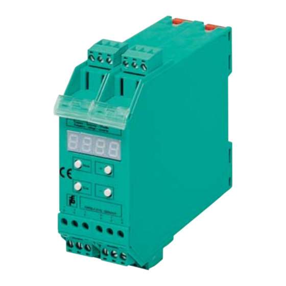
KFU8-DW-1.D Appendix Dimensions, operating and display devices Yellow LED, Relay switch state indication Drehzahlwächter Output Speed monitor 7-segment-display Mode – Control keys Enter PEPPERL+FUCHS GERMANY 10 11 12 13 14 16 17 18 "Mode" and "+": Start parameter editor "+":... -
Page 35: Connection Diagram
KFU8-DW-1.D Appendix Connection diagram NAMUR NAMUR Sensor Encoder NAMUR L+ L– L– NAMUR L- DC-3-wire DC-3-wire Bridge fitted: sensor, PNP sensor, NPN start-up bypass triggered by switching on the power supply Sensor power L– 13 supply 24 V DC Sensor power L–... -
Page 36: Functional Description
KFU8-DW-1.D Appendix Functional description Operating mode X=0: frequency measurement 0.002 Hz ... 40000 Hz X=1: rotational speed measurement 0.01 rpm ... 9999 rpm Preset at the factory: X=1 Number of pulses per revolution for rotational speed measurement (will be ignored for frequency measurement) 1 ≤... - Page 37 KFU8-DW-1.D Appendix Period for the timer function of switching relay 0.1 s ≤ XXX.X ≤ 999.9 s Preset at the factory: XXX.X=1.0 s Timer function of switching relay Preset at the factory: X=0 Function No timer function ON delay OFF delay...
- Page 38 KFU8-DW-1.D Appendix...
- Page 39 KFU8-DW-1.D Appendix...
- Page 40 Twinsburg, Ohio 44087 · USA Tel. +1 330 4253555 E-Mail: sales@us.pepperl-fuchs.com Asia Pacific Headquarters Pepperl+Fuchs Pte Ltd. Company Registration No. 199003130E Singapur 139942 Tel. +65 67799091 E-Mail: sales@sg.pepperl-fuchs.com www.pepperl-fuchs.com 129506 TDOCT0610C_ENG Subject to modifications Copyright PEPPERL+FUCHS · Printed in Germany 12/2012...
Need help?
Do you have a question about the KFU8-DW-1.D and is the answer not in the manual?
Questions and answers