Table of Contents
Advertisement
Quick Links
Please dispose of packaging for the product in a responsible
manner. It is suitable for recycling. Help to protect the
environment, take the packaging to the local amenity tip
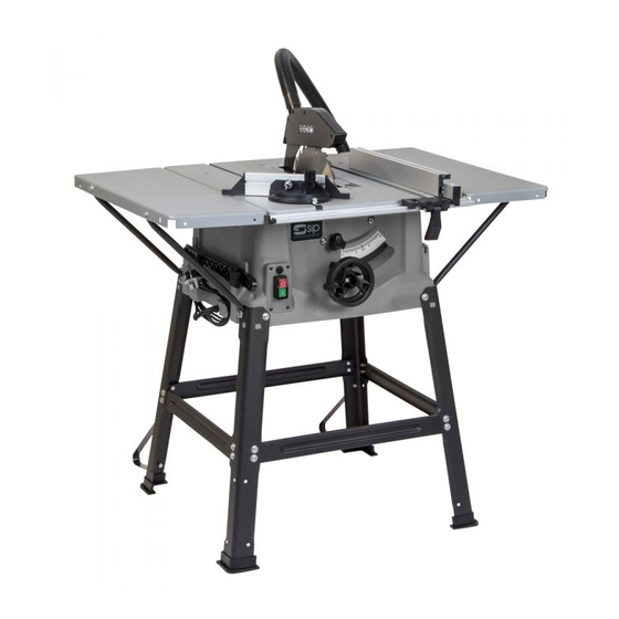
10" Table Saw
and place into the appropriate recycling bin.
With Stand
Never dispose of electrical equipment or batteries in with
your domestic waste. If your supplier offers a disposal facili-
ty please use it or alternatively use a recognised re-cycling
agent. This will allow the recycling of raw materials and help
protect the environment.
FOR HELP OR ADVICE ON THIS PRODUCT PLEASE CONTACT YOUR DISTRIBU-
TOR, OR SIP DIRECTLY ON:
TEL: 01509 500400
01986
EMAIL: sales@sip-group.com or technical@sip-group.com
www.sip-group.com
Please read and fully understand the instructions in this manual
before operation. Keep this manual safe for future reference.
Ref: 180417
28
1
Advertisement
Table of Contents

Related Manuals for SIP 01986


Summary of Contents for SIP 01986
- Page 1 This will allow the recycling of raw materials and help protect the environment. FOR HELP OR ADVICE ON THIS PRODUCT PLEASE CONTACT YOUR DISTRIBU- TOR, OR SIP DIRECTLY ON: TEL: 01509 500400 01986 EMAIL: sales@sip-group.com or technical@sip-group.com www.sip-group.com...
- Page 2 Conforms to the requirements of the following directive(s), as indicated. 2006/42/EC Machinery Directive 2014/30/EU EMC Directive 2011/65/EU RoHS Directive And the relevant harmonised standard(s), including, EN 55014-1:2006+A2:2011 EN 55014-2:1997+A2:2008 EN 61000-3-2:2014 EN 61000-3-11:2000 Signed: Mr P. Ippaso - Director - SIP (Industrial Products) Ltd Date: 15/03/2017.
-
Page 3: Table Of Contents
NOTES CONTENTS Page No. Description Safety Symbols Used Throughout This Manual Safety Instructions Contents and Accessories Guarantee Technical Specifications Electrical Connection Getting To Know Your Saw Assembly Instructions Operating Instructions Maintenance Trouble Shooting Exploded Drawing Parts List Declaration of Conformity... -
Page 4: Description
Read all these instructions before operating the saw and save this user manual for future reference. SIP recommends that this saw should not be modified or used for any application other than that for which it was designed; This table saw is designed for the longitudinal (slitting) and cross-cutting of most solid woods, coated woods, chip board, block board and similar wood derived materials, commensurate with the machine’s size. - Page 5 SAFETY INSTRUCTIONS...cont WEAR THE CORRECT CLOTHING: Do not wear loose clothing, neckties, rings, bracelets, or Ref. No. Description SIP Part No. Ref. No. Description SIP Part No. other jewellery, which may get caught in moving parts. Non-slip footwear is recommend-...
- Page 6 SAFETY INSTRUCTIONS...cont PARTS LIST designed. Ref. No. Description SIP Part No. Ref. No. Description SIP Part No. DO NOT OPERATE THE SAW IN EXPLOSIVE ATMOSPHERES: Do not use the saw in the pres- Table Insert WD01-01078 Brush Holder WD01-01113 ence of flammable liquids, gases, dust or other combustible sources. The saw may create...
- Page 7 EXPLODED DRAWING SAFETY INSTRUCTIONS...cont the saw blade. Make sure that the riving knife is always used, and set up is correctly. Use the upper blade guard and set it to the correct position. Only use saw blades for which the maximum permissible speed is not lower than the maximum spindle speed of the saw and which are suitable for the material to be cut.
-
Page 8: Contents And Accessories
CONTENTS AND ACCESSORIES TROUBLE SHOOTING Problem Possible cause Possible solution Voltage from source is low. Request a voltage check from local power company. Windings are burned out or open. Have the Motor checked, repaired or replaced. NVR Switch is defective. Have switch Circuit is overloaded with... -
Page 9: Guarantee
GUARANTEE Remove the outer flange and the old saw blade from the inner flange. This SIP table saw is covered by a 12 month parts and labour warranty covering failure Clean the blade flange thoroughly before fitting the new blade. - Page 10 ELECTRICAL CONNECTION MAINTENANCE This table saw is double insulated; This means the operator is separated from Warning! Always ensure that the saw is turned off and that the plug is disconnected from the mains supply before carrying out any adjustments, repairs or maintenance. the tool's electrical system by two complete sets of electrical insulation.
-
Page 11: Getting To Know Your Saw
OPERATING INSTRUCTIONS….cont GETTING TO KNOW YOUR SAW Slacken the thumb screws (28) and push the extrusion (27) forward until it touches the imaginary 45° line. Re-tighten the wing nuts (28). Once set in the correct position and orientation, ensure that the rip-fence is locked in position by pressing down on the locking handle (30). -
Page 12: Assembly Instructions
ASSEMBLY INSTRUCTIONS OPERATING INSTRUCTIONS….cont USING THE RIP-FENCE DANGER! Always ensure that the saw is turned off and that the plug is disconnect- ed from the mains supply before carrying out any adjustments, repairs or mainte- nance. Unpack the table saw and check it for damage which may have occurred in transit. -
Page 13: Operating Instructions
Repeat this process for the opposite side of the saw. Your SIP 10” Table Saw is fitted with a safety NVR (No Volt Release) switch (11). This Push the 4 rubber feet (16a) onto the bottom of each leg (Fig.6.1). - Page 14 ASSEMBLY INSTRUCTIONS….cont ASSEMBLY INSTRUCTIONS….cont Once the side extensions and the leg set are loosely fitted; Turn the saw over onto FITTING THE BLADE GUARD a firm level surface. Ensure that the main saw table is as level as possible. With a straight edge, or similar, set the extension tables level with the main saw bed and proceed to tighten all of the nuts and bolts etc.
Need help?
Do you have a question about the 01986 and is the answer not in the manual?
Questions and answers