Advertisement
Table of Contents
- 1 Declaration of Conformity
- 2 Table of Contents
- 3 Safety Instructions
- 4 Safety Symbols Used Throughout this Manual
- 5 Electrical Connection
- 6 Guarantee
- 7 Contents & Accessories
- 8 Technical Specifications
- 9 Getting to Know Your Bandsaw
- 10 Assembly Instructions
- 11 Operating Instructions
- 12 Maintenance Instructions
- Download this manual
Please dispose of packaging for the product in a responsible
manner. It is suitable for recycling. Help to protect the
environment, take the packaging to the local amenity tip and
place into the appropriate recycling bin.
Never dispose of electrical equipment or batteries in with your
domestic waste. If your supplier offers a disposal facility please
use it or alternatively use a recognised re-cycling agent. This
will allow the recycling of raw materials and help protect the
environment.
FOR HELP OR ADVISE ON THIS PRODUCT PLEASE CONTACT YOUR DISTRIBUTOR,
OR SIP DIRECTLY ON:
TEL: 01509500400
EMAIL: sales@sip-group.com or technical@sip-group.com
www.sip-group.com
Ref: 100813
36
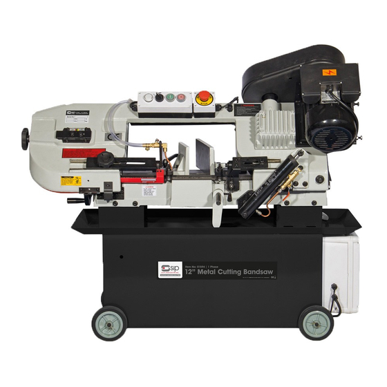
12" Metal Cutting Bandsaw
01594 & 01595
Please read and fully understand the instructions in this manual
before operation. Keep this manual safe for future reference.
1
Advertisement
Table of Contents

Related Manuals for SIP 01594


Summary of Contents for SIP 01594
- Page 1 This will allow the recycling of raw materials and help protect the environment. FOR HELP OR ADVISE ON THIS PRODUCT PLEASE CONTACT YOUR DISTRIBUTOR, OR SIP DIRECTLY ON: TEL: 01509500400 01594 & 01595 EMAIL: sales@sip-group.com or technical@sip-group.com www.sip-group.com...
-
Page 2: Declaration Of Conformity
As the manufacturer's authorised representative within the EC declare that the 12” Metal Cutting Bandsaw 1ph - SIP Pt. No. 01594 12” Metal Cutting Bandsaw 3ph - SIP Pt. No. 01595 Conforms to the requirements of the following directive(s), as indicated. -
Page 3: Table Of Contents
NOTES CONTENTS Page No. Description Safety Symbols Used Throughout This Manual Safety Instructions Electrical Connection Guarantee Technical Specifications Contents & Accessories Getting to Know Your Bandsaw Assembly Instructions Operating Instructions Maintenance Instructions Troubleshooting Wiring Diagram Exploded Diagram Parts List Notes Declaration of Conformity... -
Page 4: Safety Symbols Used Throughout This Manual
SAFETY SYMBOLS USED THROUGHOUT THIS MANUAL MAINTENANCE INSTRUCTIONS NOTES Danger / Caution: Indicates risk of personal injury and/or the possibility of damage. Warning: Risk of electrical injury or damage! Note: Supplementary information. SAFETY INSTRUCTIONS IMPORTANT: Please read the following instructions carefully, failure to do so could lead to serious personal injury and / or damage to the band- saw. - Page 5 NOTES PARTS LIST….cont SAFETY INSTRUCTIONS….cont supply. Ref. No. Description SIP Part No. Ref. No. Description SIP Part No. KEEP WORK AREA CLEAN AND WELL LIT: Cluttered work areas and dark areas invite ac- 172. Bearing cover WK04-00124 192. Nut M8 WK04-00015 cidents.
- Page 6 SAFETY INSTRUCTIONS….cont PARTS LIST….cont nance. Ref. No. Description SIP Part No. Ref. No. Description SIP Part No. Keep hands and all other body parts away from the blade. 117. Bolt M8x35 WK04-00082 144-1. Sleeve A WK04-00102 Failure to follow the warnings in this manual, may result in personal injury and/or property damage.
- Page 7 PARTS LIST….cont SAFETY INSTRUCTIONS….cont and safest performance. Ref. No. Description SIP Part No. Ref. No. Description SIP Part No. ALWAYS wear approved eye and ear protection when operating the machine. Movable vice jaw WK04-00047 92.1. Washer M8 WK04-00014 If any dust is produced, wear an approved face or dust mask.
-
Page 8: Electrical Connection
Hydraulic cylinder WK04-00009 Acme nut WK04-00032 This SIP bandsaw is fitted with a standard 230v ~ 13 amp type plug. Before using the Bolt M6x16 WK04-00010 WK04-00033 bandsaw, inspect the mains lead and plug to ensure that neither are damaged. If... -
Page 9: Guarantee
Always fully unwind the lead during use. GUARANTEE This SIP bandsaw is covered by a 12 month parts and labour warranty covering failure due to manufacturers defects. This does not cover failure due to misuse or operating... -
Page 10: Technical Specifications
TECHNICAL SPECIFICATION EXPLODED DIAGRAM SAW BASE Name 12” Metal Cutting Bandsaw 1PH 12” Metal Cutting Bandsaw 3PH Part number 01594 01595 Input Voltage 230v 400v Circular 45˚ 127mm 127mm Circular 90˚ 178mm 178mm Rectangle 45˚ 120 x 125mm 120 x 125mm Rectangle 90˚... -
Page 11: Getting To Know Your Bandsaw
WIRING DIAGRAM….cont GETTING TO KNOW YOUR BANDSAW 3 PHASE WIRING Description Reference Specification Description Reference Specification Main motor 50hZ 3ph Contactor CN6 AC24v 50Hz Coolant pump 230/400v 50Hz 40w Heat relay RHM-5M 2.4-3.6A Transformer AC400,230 24v Limit switch QKS7 250V 10A Current breaker DZ47-63 2P 10A Interlocking switch... - Page 12 GETTING TO KNOW YOUR BANDSAW….cont WIRING DIAGRAM Ref. Description Ref. Description 1 PHASE WIRING Power on light Coolant tank Coolant pump switch Pivot arm Start switch Belt guard Stop switch Moveable blade guard Emergency stop button Fixed vice jaw Motor Moving vice jaw Gearbox Filter...
-
Page 13: Assembly Instructions
TROUBLESHOOTING ASSEMBLY INSTRUCTIONS UNPACKING Symptom Possible cause Solution 1.Remove the bandsaw from the packaging, check the bandsaw for any signs of 1. Blade guides are worn. 1. Replace blade guides. 2. Blade guides not properly adjusted. 2. Adjust blade guides. damage or missing items prior to assembling. -
Page 14: Operating Instructions
ASSEMBLY INSTRUCTIONS….cont MAINTENANCE INSTRUCTIONS….cont thinner or lacquer thinner as these will damage the painted surfaces. Note: The outer bearing shaft is eccentric and is the one to adjust, the inner bearing shaft is fixed and can not be adjusted. REMOVING THE TRANSIT BOLT Before the bandsaw can be used the transit bolt and Note: Never attempt to adjust the blade guide bearings whilst the ma- bracket must be removed;... - Page 15 MAINTENANCE INSTRUCTIONS….cont OPERATING INSTRUCTIONS….cont SETTING THE BLADE SQUARE TO THE BED AT 90˚ Speed Speed Speed Speed Material M/Min Material M/Min Material M/Min Material M/Min 1.Ensure the bow is at its lowest position. (FPM) (FPM) (FPM) (FPM) 2.Disconnect from the mains supply. Set square 3.Place an engineer`s set square onto the bed and touching the blade (Fig.12).
- Page 16 OPERATING INSTRUCTIONS….cont MAINTENANCE INSTRUCTIONS….cont Blade tension is important for the correct operation of the bandsaw; the blade tension OPERATING THE VICE should be set between 700-900kgs. Setting The Vice to 90°: To set the blade correctly without using a blade tension gauge, take the following 1.
-
Page 17: Maintenance Instructions
MAINTENANCE INSTRUCTIONS OPERATING INSTRUCTIONS….cont CHANGING THE BLADE Using the vice: 1. Select the desired angle you wish to cut at and adjust the vice accordingly. Caution: Before carrying out any maintenance always disconnect the 2. Ensure the bolts (Fig.13,A) are tight. bandsaw from the mains supply. - Page 18 OPERATING INSTRUCTIONS….cont OPERATING INSTRUCTIONS….cont HYDRAULIC CYLINDER ADJUSTMENT 9.Plug in to the mains supply and turn the coolant pump on. 10.Start the saw. 11.To bring the blade in to contact with the material to be cut, open the tap on the The hydraulic cylinder has an adjustable rate of de- hydraulic cylinder, if the blade jams then immediately turn the bandsaw off and refer scent;...
Need help?
Do you have a question about the 01594 and is the answer not in the manual?
Questions and answers