Table of Contents
Advertisement
Quick Links
Please dispose of packaging for the product in a responsible
manner. It is suitable for recycling. Help to protect the
environment, take the packaging to the local amenity tip
and place into the appropriate recycling bin.
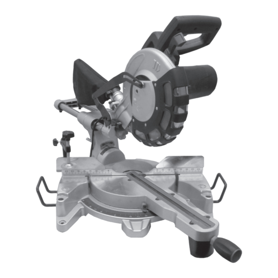
10" Compound Sliding Mitre
Saw
Never dispose of electrical equipment or batteries in with
your domestic waste. If your supplier offers a disposal facili-
With Laser
ty please use it or alternatively use a recognised re-cycling
agent. This will allow the recycling of raw materials and help
protect the environment.
FOR HELP OR ADVISE ON THIS PRODUCT PLEASE CONTACT YOUR DISTRIBUTOR,
OR SIP DIRECTLY ON:
TEL: 01509500400
01511
EMAIL: sales@sip-group.com or technical@sip-group.com
www.sip-group.com
Please read and fully understand the instructions in this manual
before operation. Keep this manual safe for future reference.
Ref: 270214
32
1
Advertisement
Table of Contents

Related Manuals for SIP 01511


Summary of Contents for SIP 01511
- Page 1 This will allow the recycling of raw materials and help protect the environment. FOR HELP OR ADVISE ON THIS PRODUCT PLEASE CONTACT YOUR DISTRIBUTOR, OR SIP DIRECTLY ON: TEL: 01509500400 01511 EMAIL: sales@sip-group.com or technical@sip-group.com www.sip-group.com...
-
Page 2: Declaration Of Conformity
Leicestershire LE12 9NH England As the manufacturer's authorised representative within the EC declare that the 10” Compound Sliding Mitre Saw - SIP Pt. No. 01511 Conforms to the requirements of the following directive(s), as indicated. 2006/95/EC Low Voltage Directive 2006/42/EC... -
Page 3: Table Of Contents
NOTES CONTENTS Page No. Description Safety Symbols Used Throughout This Manual Safety Instructions Technical Specifications Electrical Connection Guarantee Contents and Accessories Getting To Know Your Saw Assembly Instructions Operating Instructions Maintenance Exploded Drawing Parts List Declaration of Conformity... -
Page 4: Safety Symbols Used Throughout This Manual
149. Locking shoe WD01-00635 174. Cap head bolt WD01-00660 ture reference. SIP recommends that this tool should not be modified or used for any application oth- 150. Spring pin WD01-00636 175. Knob WD01-00661 er than that for which it was designed. If you are unsure of its relative applications do 151. - Page 5 PARTS LIST….cont SAFETY INSTRUCTIONS...cont above the elbow. Ref. No. Description SIP Part No. Ref. No. Description SIP Part No. USE SAFETY GOGGLES AND EAR PROTECTION: Wear CE approved safety goggles at all Screw WD01-00560 Spring pin WD01-00589 times, Normal spectacles only have impact resistant lenses, they are NOT safety glass-...
- Page 6 SAFETY INSTRUCTIONS...cont PARTS LIST both hands to operate the tool. Ref. No. Description SIP Part No. Ref. No. Description SIP Part No. DO NOT OVERREACH: Keep proper footing and balance at all times. WD01-00500 Mains leads holder WD01-00530 USE THE RIGHT TOOL: Do not use the tool or attachment to do a job for which it was...
- Page 7 EXPLODED DRAWING B SAFETY INSTRUCTIONS...cont Warning: The laser beam can potentially cause severe eye damage. Never look or stare directly into the laser beam. Warning: During use, do not point the laser beam at people, directly or indirectly through reflecting surfaces. This laser complies with class 2 according to EN 60825-1:2007.
-
Page 8: Technical Specifications
It must be under- stood by the operator that common sense and caution are factors which can- not be built into this product, but must be applied. TECHNICAL SPECIFICATIONS Part number 01511 Input voltage 230v ~ 50hz Power 2000 w... -
Page 9: Electrical Connection
MAINTENANCE….cont ELECTRICAL CONNECTION This mitre saw is double insulated. This means the operator is separated from The motor of the saw should be cleared of any wood chippings as there would the tool's electrical system by two complete sets of electrical insulation. be a risk of fire if they are allowed to build up over time (a soft brush or dry air could be used to clear the motor). -
Page 10: Guarantee
MAINTENANCE….cont down to the limit mark, see Fig.6. Keep the carbon brushes clean and free to slip in This SIP 10” compound sliding mitre saw is covered by a 12 month parts and labour the holders. warranty covering failure due to manufacturers defects. This does not cover failure... -
Page 11: Getting To Know Your Saw
MAINTENANCE….cont GETTING TO KNOW YOUR SAW Fig. 3 Remove the outer blade flange and the blade. Wipe a drop of oil onto the inner and outer blade flanges. Fit the new blade onto the spindle, make sure that the blade has the appropri- ate dimensions and that the inner blade flange sits properly behind the blade. - Page 12 GETTING TO KNOW YOUR SAW….cont MAINTENANCE….cont Loosen the locking nut on the bevel angle adjust bolt (45°) (32). Turn the angle adjust bolt (32) until an angle of 45° is achieved. Lock off the locking nut whilst ensuring that the angle kept. Check if the bevel angle pointer is pointing to 45°...
-
Page 13: Assembly Instructions
MAINTENANCE….cont ASSEMBLY INSTRUCTIONS CHECKING AND SETTING THE BEVEL ANGLE @ 90° FITTING THE DUST COLLECTION BAG Loosen the sliding rail lock (27); push the saw head back as far as it will go and re-tighten the sliding rail lock (27). Loosen the mitre lock (14);... -
Page 14: Operating Instructions
OPERATING INSTRUCTIONS MAINTENANCE Warning! Always ensure that the saw is turned off and that the plug is disconnected Warning: Do not stare into the laser beam as this is dangerous and will from the mains supply before carrying out any adjustments, repairs or maintenance. damage your eyes. - Page 15 OPERATING INSTRUCTIONS….cont OPERATING INSTRUCTIONS….cont Function: Place the work-piece flat on the table with one edge securely against the fence (12). Once the depth stop is set; the blade will not cut all the way through the work-piece Use the clamp assembly (20) to secure the work-piece. (depending on the depth that it is set to).
- Page 16 OPERATING INSTRUCTIONS….cont OPERATING INSTRUCTIONS….cont Turn on the laser by pressing the laser On/Off switch (25). MAKING A COMPOUND MITRE CUT Hold the operating handle (4) firmly and squeeze the trigger switch (5); allow the blade to reach maximum speed. A compound mitre cut involves using a mitre angle and a bevel angle at the same Press the blade guard release lever (6) and slowly lower the blade onto and time.
Need help?
Do you have a question about the 01511 and is the answer not in the manual?
Questions and answers
should this work on 250volt ****amp system as mine keeps switching off the trip , have check brushes etc ,all seems to be ok ???
The manual states that the correct voltage and fuse protection must be used. If the system keeps tripping, it could indicate an issue with voltage compatibility, fuse rating, or power supply capacity. Ensure that the correct voltage and fuse are used and that any extension lead is rated properly to avoid voltage drops. If the issue persists, further investigation into the power supply or tool condition may be needed.
This answer is automatically generated