Table of Contents
Advertisement
Please dispose of packaging for the product in a responsible
manner. It is suitable for recycling. Help to protect the
environment, take the packaging to the local amenity tip
and place into the appropriate recycling bin.
Never dispose of electrical equipment or batteries in with
your domestic waste. If your supplier offers a disposal facili-
ty please use it or alternatively use a recognised re-cycling
agent. This will allow the recycling of raw materials and help
protect the environment.
FOR HELP OR ADVISE ON THIS PRODUCT PLEASE CONTACT YOUR DISTRIBUTOR,
OR SIP DIRECTLY ON:
TEL: 01509500400
EMAIL: sales@sip-group.com or technical@sip-group.com
www.sip-group.com
Ref: 250113
28
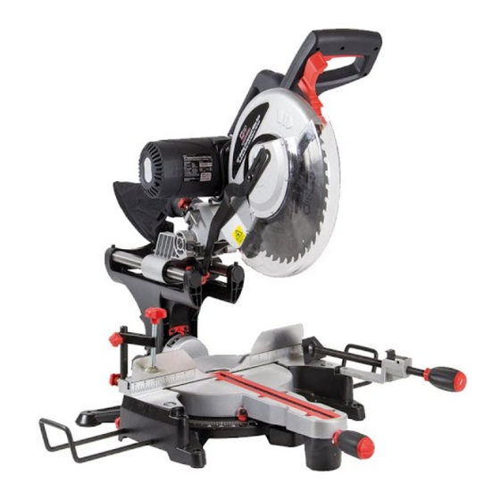
12" Double Bevel
Mitre Saw
01504
Please read and fully understand the instructions in
this manual before operation. Keep this manual
safe for future reference
1
Advertisement
Table of Contents

Related Manuals for SIP 01504


Summary of Contents for SIP 01504
- Page 1 This will allow the recycling of raw materials and help protect the environment. FOR HELP OR ADVISE ON THIS PRODUCT PLEASE CONTACT YOUR DISTRIBUTOR, OR SIP DIRECTLY ON: TEL: 01509500400 01504 EMAIL: sales@sip-group.com or technical@sip-group.com www.sip-group.com...
-
Page 2: Declaration Of Conformity
Leicestershire LE12 9NH England As the manufacturer's authorised representative within the EC declare that the 12” Double Bevel Mitre Saw - SIP Pt. No. 01504 Conforms to the requirements of the following directive(s), as indicated. 2006/95/EC Low Voltage Directive 2006/42/EC... -
Page 3: Table Of Contents
NOTES CONTENTS Page No. Description General Safety Instructions Specific Safety Instructions Technical Specifications Electrical Connection Guarantee Contents and Accessories Getting To Know Your Saw Assembly Instructions Operating Instructions Maintenance Exploded Diagram Parts List Notes Declaration of Conformity... - Page 4 Read all these instructions before operating the tool and save this user manual for fu- ture reference. SIP recommends that this tool should not be modified or used for any application oth- er than that for which it was designed. If you are unsure of its relative applications do not hesitate to contact us and we will be more than happy to advise you.
-
Page 5: General Safety Instructions
PARTS LIST….cont GENERAL SAFETY INSTRUCTIONS...cont comes to a complete stop. Ref No. Description SIP Part No. Ref No. Description SIP Part No. DO NOT ABUSE THE MAINS LEAD: Never carry the tool by the mains lead or pull it to re-... -
Page 6: Specific Safety Instructions
SPECIFIC SAFETY INSTRUCTIONS PARTS LIST….cont Use only the blade flange specified for this tool. Ref No. Description SIP Part No. Ref No. Description SIP Part No. Be careful not to damage the arbor, flange (especially the installing surface). WD01-00289 Lock boot WD01-00320 Damage to these parts could result in blade breakage. - Page 7 PARTS LIST….cont SPECIFIC SAFETY INSTRUCTIONS...cont This laser complies with class 2 according to EN 60825-1:2007. Ref No. Description SIP Part No. Ref No. Description SIP Part No. The unit includes no servicing components. Do not open the housing for any...
-
Page 8: Technical Specifications
SPECIFIC SAFETY INSTRUCTIONS….cont PARTS LIST Ref No. Description SIP Part No. Ref No. Description SIP Part No. Caution: The warnings and cautions mentioned in this user manual can not cover all possible conditions and situations that may occur. It must... -
Page 9: Electrical Connection
EXPLODED DIAGRAM ELECTRICAL CONNECTION This mitre saw is double insulated. This means the operator is separated from the tool's electrical system by two complete sets of electrical insulation. This saw is fitted with a standard UK type 230v ~ plug. Before using the tool inspect the cable and plug to ensure that neither are damaged. -
Page 10: Guarantee
GENERAL INSPECTION: Cleaning and maintenance of this saw is mainly common sense some points for This SIP 12” double bevel saw is covered by a 12 month parts and labour warranty guidance are as follows: covering failure due to manufacturers defects. This does not cover failure due to mis-... -
Page 11: Getting To Know Your Saw
MAINTENANCE….cont GETTING TO KNOW YOUR SAW Loosen the locking nut on one of the bevel adjustment screws (33 or 34). Loosen the bevel lock (16). Pull out the bevel positive stop knob (39) whilst pushing the saw head to 45° ei- ther left or right depending on which adjustment screw has been loosened. -
Page 12: Assembly Instructions
GETTING TO KNOW YOUR SAW….cont MAINTENANCE Laser assembly Mitre table Warning! Always ensure that the saw is turned off and that the plug is disconnected Laser light on/off switch Mitre scale from the mains supply before carrying out any adjustments, repairs or maintenance. Laser cover Table insert Laser pitch control... -
Page 13: Operating Instructions
OPERATING INSTRUCTIONS OPERATING INSTRUCTIONS….cont A compound mitre cut involves using a mitre angle and a bevel angle at the same time. It is used in making picture frames, to cut mouldings, making boxes with sloping Warning: Do not stare into the laser beam as this is dangerous and will sides and for roof framing. - Page 14 OPERATING INSTRUCTIONS….cont OPERATING INSTRUCTIONS….cont MAKING A BEVEL CUT: Note: It is possible to remove the clamp assembly (10) by loosening the clamp assembly lock (11) and moving it to the other side of the table. A bevel cut of up to 45° (to the left or to the right) can be achieved by using the fol- Make sure the clamp assembly lock is tight before using the clamp.
Need help?
Do you have a question about the 01504 and is the answer not in the manual?
Questions and answers