Table of Contents
Advertisement
Quick Links
Please dispose of packaging for the product in a responsible
manner. It is suitable for recycling. Help to protect the
environment, take the packaging to the local amenity tip and
place into the appropriate recycling bin.
Never dispose of electrical equipment or batteries in with your
domestic waste. If your supplier offers a disposal facility please
use it or alternatively use a recognised re-cycling agent. This
will allow the recycling of raw materials and help protect the
environment.
FOR HELP OR ADVISE ON THIS PRODUCT PLEASE CONTACT YOUR DISTRIBUTOR,
OR SIP DIRECTLY ON:
TEL: 01509500400
EMAIL: sales@sip-group.com or technical@sip-group.com
www.sip-group.com
Ref: 041113
36
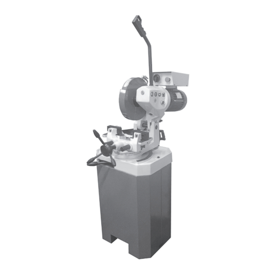
12" Industrial Circular Saw
01565
Please read and fully understand the instructions in this manual
before operation. Keep this manual safe for future reference.
1
Advertisement
Table of Contents

Subscribe to Our Youtube Channel
Related Manuals for SIP 01565


Summary of Contents for SIP 01565
- Page 1 This will allow the recycling of raw materials and help protect the environment. FOR HELP OR ADVISE ON THIS PRODUCT PLEASE CONTACT YOUR DISTRIBUTOR, OR SIP DIRECTLY ON: TEL: 01509500400 01565 EMAIL: sales@sip-group.com or technical@sip-group.com www.sip-group.com...
-
Page 2: Declaration Of Conformity
Leicestershire LE12 9NH England As the manufacturer's authorised representative within the EC declare that the 12” Industrial Circular Saw 3PH - SIP Part. No. 01565 Conforms to the requirements of the following directive(s), as indicated. 2006/95/EC Low Voltage Directive 2006/42/EC... -
Page 3: Table Of Contents
NOTES CONTENTS Page No. Description Safety Symbols Used Throughout This Manual Safety Instructions Electrical Connection Guarantee Technical Specifications Blade Selection Contents & Accessories Getting to Know Your Circular saw Assembly Instructions Operating Instructions Maintenance Instructions Troubleshooting Wiring Diagram Exploded Drawing Parts List Notes Declaration of Conformity... -
Page 4: Safety Symbols Used Throughout This Manual
SAFETY SYMBOLS USED THROUGHOUT THIS MANUAL PARTS LIST….cont Ref. No. Description SIP Part No. Ref. No. Description SIP Part No. Danger / Caution: Indicates risk of personal injury and/or the possibility of damage. 645. Washer WK03-00210 674. Bolt M5x12 WK04-00093 646. - Page 5 PARTS LIST….cont SAFETY INSTRUCTIONS….cont rounding the work area. Do not use in environments with a potentially explosive atmos- Ref. No. Description SIP Part No. Ref. No. Description SIP Part No. phere. KEEP CHILDREN AND UNTRAINED PERSONNEL AWAY FROM THE WORK AREA: All visitors 402.
- Page 6 USE ONLY RECOMMENDED ACCESSORIES: Consult this user manual, your distributor or 104. Bolt M6x12 WK04-00038 307. Pipe clamp WK03-00122 SIP directly for recommended accessories. Follow the instructions that accompany the 105. Spring washer M6 WK03-00102 308. WK03-00123 accessories. The use of improper accessories may cause hazards and will invalidate 106.
- Page 7 EXPLODED DRAWING….cont SAFETY INSTRUCTIONS….cont Use of improper accessories may cause damage to the circular saw and sur- rounding area as well as increasing the risk of injury. Do not modify the circular saw to do tasks other than those intended. When sawing always use the vice to hold the material;...
- Page 8 SAFETY INSTRUCTIONS….cont EXPLODED DRAWING….cont When using the circular saw for certain operations, particularly during extended periods; ensure the operator as well as those in the area wear ear protection. When using the circular saw always ensure the operator as well as those in the area wear eye protection.
-
Page 9: Electrical Connection
Connecting to the power supply: This SIP circular saw requires 400v 50hz supply. Before using the circular saw, inspect the mains lead and plug (where applicable) to ensure that neither are damaged. If any damage is visible have the circular saw inspected / repaired by a suitably quali- fied person. -
Page 10: Guarantee
Always fully unwind the lead during use. GUARANTEE This SIP circular saw is covered by a 12 month parts and labour warranty covering fail- ure due to manufacturers defects. This does not cover failure due to misuse or operat-... -
Page 11: Technical Specifications
100x100 140x90 50x50 60˚ 90x90 90x90 90x90 100x90 40x40 Note: If none of the above solutions work then contact your local distributor for 45˚ 90x90 90x90 90x90 100x90 40x40 repair, or contact SIP technical for more advise. 01509 500400 technical@sip-group.com... -
Page 12: Blade Selection
BLADE SECTION MAINTENANCE….cont LUBRICATING THE CIRCULAR SAW Solid Bar Size 10mm 15mm 20mm 25mm 15mm 20mm 25mm 35mm Hollow Section Wall thickness Tooth Pitch The pivots of the saw head must be greased at least every three months, Hollow on the rear of the machine. There section are two grease nipples (A), apply grease to these points. -
Page 13: Getting To Know Your Circular Saw
GETTING TO KNOW YOUR CIRCULAR SAW CHANGING THE INLINE FILTER Note: Its best to change the filter at least once a year, or sooner if used more often in a working environment. SIP replacement filter code WK03-00095 Inline The filter is located at the rear of the... -
Page 14: Assembly Instructions
ASSEMBLY INSTRUCTIONS MAINTENANCE….cont Blade FITTING THE CIRCULAR SAW TO THE STAND shaft Place the new blade over the blade Danger / Caution: This is a minimum of a 2 man operation to remove this circular saw from its packaging as its extremely heavy, failing to do this can have serious shaft lip. - Page 15 MAINTENANCE ASSEMBLY INSTRUCTIONS….cont FITTING THE HANDLE LEVER CHANGING THE BLADE Handle lever Turn the circular saw to the `OFF` position. Handle Items needed Isolate the saw from the mains spply. screws Raise the head upwards. Remove hex. bolt (A). Handle Micro switch Handle trigger...
- Page 16 ASSEMBLY INSTRUCTIONS….cont OPERATING INSTRUCTIONS….cont SETTING UP FOR AN ANGLED CUT Push the other half of the handle onto the The vice is fixed and the angle can only be set by rotating the head, up to 45˚right or handle that’s already fixed to the head lever, 45˚...
- Page 17 OPERATING INSTRUCTIONS….cont ASSEMBLY INSTRUCTIONS….cont WIRING THE COOLANT PUMP Warning: Disconnect from the mains supply before wiring the coolant pump, Move the vice hand-wheel so you have enough this is potentially dangerous and could lead to personal injury. clearance to fit your material. Place your material between the vice jaws.
-
Page 18: Operating Instructions
OPERATING INSTRUCTIONS OPERATING INSTRUCTIONS….cont FILLING THE COOLANT TANK Note: Before any cuts are made it is best to get into a routine of turning the coolant tap to the open position, this will prolong the life of the blade. Remove the four hex bolts (A) and remove the cover. Slide the coolant tank out.
Need help?
Do you have a question about the 01565 and is the answer not in the manual?
Questions and answers