Advertisement
Quick Links
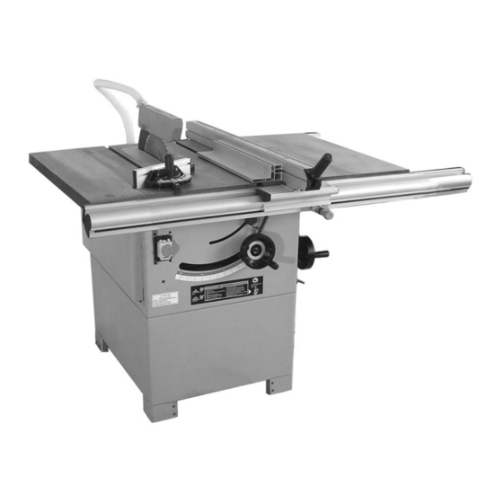
12" Heavy Duty
Please dispose of packaging for the product in a responsible
manner. It is suitable
for recycling.
Help to protect the
environment, take the packaging to the local amenity tip and
place into the appropriate recycling bin.
Table Saw
Never dispose of electrical equipment or batteries in with
your domestic waste. If your supplier offers a disposal facil-
ity please use it or alternatively use a recognised re-cycling
agent. This will allow the recycling of raw materials and help
protect the environment.
Please read and fully understand the instructions in this
FOR HELP OR ADVISE ON THIS PRODUCT PLEASE CALL OUR
CUSTOMER SERVICE HELP LINE : 01509 500359
manual before operation. Keep this manual safe for
future reference
Ref:060406
44
1
Advertisement

Related Manuals for SIP 01446


Summary of Contents for SIP 01446
- Page 1 12” Heavy Duty Please dispose of packaging for the product in a responsible manner. It is suitable for recycling. Help to protect the environment, take the packaging to the local amenity tip and place into the appropriate recycling bin. Table Saw Never dispose of electrical equipment or batteries in with your domestic waste.
- Page 2 GELDERS HALL ROAD SHEPSHED LOUGHBOROUGH LEICESTERSHIRE LE12 9NH Declare that the 12” Heavy Duty Table Saw SIP Pt No: 01446 Complies with the following EEC Directives their supporting Statutory Instruments and the relevant standard where applicable: 98/37/EC Machinery Directive 73/23/EEC...
- Page 3 PARTS LIST (C) CONTENTS Ref. No. Description Qty. C-30 Square Nut M6 C-31 Cross Recessed Pan Head Screw M6 X 16 Page No. Description C-32 Board Instead Of Nut Contents C-33 Cross Recessed Countersunk Screw General Safety Instructions C-34 Left End Cap For Scale Indicator Housing Specific Safety Instructions C-35 Scale Indicator Housing...
-
Page 4: Table Of Contents
Cross Recessed Pan Head Screw M5 X 10 SIP recommends that this tool should not be modified or used for any application other than that for which it was designed. If you are unsure of its relative applications... - Page 5 EXPLODED DIGRAM (C) GENERAL SAFETY INSTRUCTIONS….cont NEVER LEAVE THE TOOL RUNNING / CONNECTED WHILST UNATTENDED: Turn off the tool and disconnect it from the mains supply between jobs. Do not leave machine until it comes to a complete stop. DO NOT ABUSE THE MAINS LEAD: Never carry the tool by the mains lead or pull it to remove the plug from the mains socket.
- Page 6 SPECIFIC SAFETY INSTRUCTIONS PARTS LIST (B) 1. Use only the blade flange specified for this tool. Ref. No. Description Qty. 2. Be careful not to damage the arbor, flange (especially the installing surface) or B-94 Elastic Lock bolt. Damage to these parts could result in blade breakage. B-95 Lock Nail Bush 3.
-
Page 7: Large Washer 8
PARTS LIST (B) SAFETY DEVICES Blade guard: Ref. No. Description Qty. B-63 Motor Wheel • The blade guard (a) protects against uninten- tional contact with the saw blade and from air- B-64 Hexagon Socket Cap Head Screw M8X24 borne chips / debris. B-65 Single Coil Spring Lock Washer 8 B-66... -
Page 8: Cross Recessed Countersunk Head Screw M5 X 8
B-45 Spring Dowel 4 X 28 TECHNICAL SPECIFICATIONS B-46 Adjusting Thread Rod B-47 Worm-Wheel Connecting Rod Nail A Part number 01446 B-48 Worm-Wheel Connecting Rod Input voltage 230v / 50 hz B-49 Worm-Wheel Connecting Rod Nail B Input fuse rating... - Page 9 Press Board For Riving Knife Arbor lock shaft. B-19 Riving Knife Push stick. B-20 Flower Nut Mounting plate for mobile wheel kit (SIP Part no. 06920) * Fixing kit (nuts, bolts etc). B-21 Large Washer 6 B-22 Step Bolt M6 X 46 B-23...
- Page 10 GETTING TO KNOW YOUR SAW EXPLODED DIAGRAM (B) Ref: Description Ref: Description Extension Table Front Fence Rail Mitre Gauge Rip-Fence Main ON/OFF (NVR) Switch Rear Fence Rail Blade Height Adjustment Blade guard Blade Angle Adjustment Extraction Hose Fence Micro Adjust...
-
Page 11: Cross Recessed Pan Head Screw M4 X 8
Guarantee: A-59 Switch Bottom Board This sip “pro” table saw is covered by a 24 month parts and labour warranty covering A-60 Lock Nut M8 failure due to manufacturers defects. This does not cover failure due to misuse or op-... -
Page 12: Washer 6
Qty. Rear Rail This sip “pro” table saw is supplied without a plug fitted; due to the fuse rating (16 amps) the saw is not classed as a “domestic item”. A plug with a rating of at least 16 Step Bolt M8 X 25... - Page 13 Note: Although all 4 feet look similar, there are some differences that mean that each foot should only be fitted in its correct position. This is to allow you to fit the optional wheel kit (SIP Part no. 06920) should you wish to at a later date.
- Page 14 * Please note that a retro fit kit may be required to allow the wheel kit to fit some older versions of the SIP Note: The pictures are shown as if the saw was the correct way up rather Pro range.
- Page 15 TROUBLESHOOTING….cont ASSEMBLY INSTRUCTIONS….cont Problem Possible cause Possible solution Fitting the extraction assembly: Table saw vibrates exces- • • Floor surface is uneven. Sit the saw on a level • Fit the extraction hose outlet adaptor to the rear panel of the saw stand by sively: •...
-
Page 16: Rip Fence
ASSEMBLY INSTRUCTIONS….cont TROUBLESHOOTING • The saw can now be turned the correct way up and completely removed from Problem Possible cause Possible solution it’s packaging. Motor is slow or weak: • • Voltage from source is Request a voltage check low. - Page 17 CARE AND MAINTENANCE….cont ASSEMBLY INSTRUCTIONS….cont • Sit a straight edge across the extension table, or tables depending on how long Replacing / tensioning the drive belt: your straight edge is, and across the main saw bed. The main drive belt is set at the factory to the correct tension, but time and use may mean that the belt needs to be re-tensioned.
- Page 18 ASSEMBLY INSTRUCTIONS….cont CARE AND MAINTENANCE….cont • Adjust the distance between the blade and the riving knife (b). • Insert the 5 square head bolts into the holes on the front of the main table and extension tables, so the bolt heads extend out 6 mm. •...
- Page 19 CARE AND MAINTENANCE….cont ASSEMBLY INSTRUCTIONS….cont • Insert the 5 square head bolts into the holes to the rear of the main table and extension tables so the bolt heads extend out approximately 6 mm. Note: The arbor nut has a left handed thread. •...
- Page 20 ASSEMBLY INSTRUCTIONS….cont CARE AND MAINTENANCE • Slide the rip fence against the saw blade, check that the red line of scale mount Caution! lens lines up with the “0” on the scale which is located on the front rail. • If it does not, slide the front fence rail left / right until it does.
- Page 21 OPERATING INSTRUCTIONS….cont ASSEMBLY INSTRUCTIONS….cont Fitting the outlet to blade guard extraction hose: Making cuts with the rip-fence: • Fit 1 small Ø hose clip over 1 end of the outlet to blade guard. Use the push stick if distance between rip fence and saw blade is less than •...
- Page 22 OPERATING INSTRUCTIONS OPERATING INSTRUCTIONS….cont Caution: This saw may only be operated by one person at a time. Making straight cuts: Other persons should stay a safe distance from the saw. Caution: For safe operation, do not force the work-piece into the blade, feed it slowly and evenly and let the saw do the work.
Need help?
Do you have a question about the 01446 and is the answer not in the manual?
Questions and answers
When i raise the blade the brake bar keeps on engaging