
Related Manuals for MiLAN MIL-S3580


Summary of Contents for MiLAN MIL-S3580
- Page 1 24 Port Managed Switch with 2 Optional Gigabit/Fiber ports...
- Page 3 - EN60950 (IEC950) - Product Safety MiLAN Technology warrants to the original consumer or purchaser that each of its product and component thereof, will be free from defects in material and/or workmanship for a period of five years from the original factory shipment date.
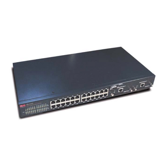
- Page 4 1. Introduction The MIL-S3580 Managed Switch is designed to provide your network with Ethernet, Fast Ethernet, Gigabit Ethernet connectivity over twisted pair and fiber optic cabling. Two expansion slots on the front further add to the flexibility of the systems Figure 1-1.
-
Page 5: Management Features
Management Features Console and Telnet Configuration Web-based management SNMP network management IEEE 802.1Q Tagging VLAN and Port-Based VLAN support IEEE802.3x Flow Control Mechanism for Full-duplex mode and Backpressure for Half-duplex IEEE 802.1D Blocking, Learning, and Forwarding states support for Spanning Tree Protocol IEEE 802.3ac extends the maximum Ethernet Length to 1522 to add the 4-Byte VLAN Tag... -
Page 6: Package Contents
MIL-S3580 Rack-mounted Kit Power Cord Figure 1-2. Package Contents Compare the contents of your MIL-S3580 package with the standard checklist above. If any item is missing or damaged, please contact your local dealer for service. Management Methods The MIL-S3580 supports the following management methods:... -
Page 7: Console And Telnet Management
Console and Telnet Management Console Management is done through the RS-232 Console Port. Managing the MIL-S3580 in this method requires a direct connection between a PC and the MIL-S3580. Telnet management is done over the network. Once the MIL-S3580 has an IP and is on the network, you can use Telnet to log in and change or view the configuration. -
Page 8: Hardware Description
1 Port Gigabit 1000BASE-T Switch Modules, 1 Port Gigabit 1000BASE-SX/LX Fiber Modules. 1 Port 100BASE-FX Fiber Modules Console Port : Console Management can be done through the Console Port. It requires a direct connection between the MIL-S3580 and an end station via an RS-232 cable. - Page 9 LED Indicators: Figure 2-2. LED Indicators All LED indicators are located on the front left panel of the MIL-S3580. They provide a real-time indication of system and operational status. The following table gives descriptions of the LED status and Status...
-
Page 10: Rear Panel
Rear Panel The 3-pronged power plug and ON/OFF switch are located on the rear panel of the MIL-S3580. The switch works in the range 100-240VAC, 50-60Hz. Figure 2-3. Rear Panel of the MIL-S3580 Power On After all network cables are connected, plug the power cord into the power socket on the back panel and the other end into a power outlet. -
Page 11: Connecting To The Network
Airflow around the switch and through its vents on the rear cannot be restricted. Mounting the Switch The MIL-S3580 is suitable for use in an office environment where it can be rack-mounted in standard EIA 19-inch racks or as a standalone device. -
Page 12: Desktop Mounting
: Do not place objects on top of the switch. Rack-mounted Installation The MIL-S3580 comes with a rack-mount kit and can be mounted in an EIA standard sized, 19-inch rack. The switch can be placed in a wiring closet with other equipment. -
Page 13: Connecting To The Switch
DB-9 connector to connect a terminal or PC to the console port. The console configuration (out-of-band management) allows you to set your switch to enable a user at a remote console terminal to communicate with the MIL-S3580 as if the console terminal were directly connected to it. -
Page 14: Login In The Console Interface
Figure 3-4. Connecting the MIL-S3580 to a Terminal via RS-232 Cable Login in the Console Interface When the physical connection between the switch and the PC is established, turn on the PC and run a terminal emulation program or Hyper Terminal and configure... -
Page 15: User Interface
Size to 25. Under Emulation, select the VT-100/ANSI radio button. User Interface The switch offers a menu-driven console interface. Use <Tab> key or the <arrow> keys to move within menus and sub-screens. To select a menu, press the appropriate <arrow>... -
Page 16: First Screen
First Screen Figure 3-6. First Screen Display in Console Interface Once you have configured your system terminal and started the switch, you can login to the console interface. The default username is admin. There is no password required. You can change both the user name and password in the User Authentication Menu option, which appears on the Main Menu. -
Page 17: System Information
The system information screen displays information such as hardware, software versions, and system up time. You can also enter specific information about you and your organization. This information about the switch is available through any SNMP manager. In each field, 48 characters can be entered. -
Page 18: Serial Port Configuration
0.0.0.0. After changing any of the settings, you need to save the information and reset the switch in order for the changes to take effect. Also note that the value under Current column will not reflect the changes you made until the next time you login after resetting the switch. -
Page 19: Snmp Community Setup
2.3. SNMP Community Setup Figure 3-11. SNMP Community Menu Use the SNMP communities to restrict access to the switch by SNMP management stations by adding editing or disabling SNMP communities. You can configure up to 6 SNMP communities, each with either a restricted read-only or unrestricted read/write access. -
Page 20: Trap Receiver
2.4. Trap Receiver Figure 3-12. Trap Receiver Menu A trap receiver is a management station designated by the switch to receive SNMP traps sent from the switch. Use Trap Receiver screen to designate certain community to receive trap(s) generated by the system. In the default configuration, no trap receivers are configured and the authentication trap is disabled. -
Page 21: Trap Filter Setup
This menu allows you to enable/disable Web-Based management capability. If disabled, there is no access to management function through the use of a Web browser such as Microsoft Internet Explorer or Netscape. 2.6. Trap Filter Setup Figure 3-14. Trap Filter Setup Menu The system will generate a set of SNMP traps upon the occurrence of an event. - Page 22 Use <Space Bar> to toggle the Enable/Disable field and type in the appropriate value in the Time and Priority fields. Spanning Tree Enable State is disabled by default on the MIL-S3580. The switch uses the IEEE802.1D Spanning Tree Protocol (STP), when enabled, to ensure that only one path at a time is active between any two nodes on the network.
- Page 23 VLAN, the port accepts the frame. If they belong to different VLANs, the port discards the frame. If Ingress filtering is disabled, any tagged frame is accepted on any port on the switch. It does not matter whether the frame and port belong to the same or different VLANs.
-
Page 24: Switch Port Configuration
Video is a multicast application. IGMP Snooping enables the switch to monitor the flow of queries from the devices and the routers. IGMP Snooping improves the switch's performance by restricting the flow of multicast packets to only those switch ports, which have devices receiving the multicast (video). -
Page 25: Individual Port Configuration
3.2. Individual Port Configuration Figure 3-18. Switch Port Configuration Menu In Switch Port Configuration Menu, you can configure basic characteristics such as speed, flow control, and VLAN ID as well as the following features supported by the switch: Port Description - Sixteen characters can be entered to identify the port. - Page 26 Configuration takes effect immediately after saving, with no resetting of the switch necessary. The various levels are listed below. 10Mb 312Kb 625KB 100Mb 3.12Mb 6.25Mb 1000Mb 31.2Mb 62.5Mb Table 3-1. Eight Levels of Bandwidth Provisioning Default Port VLAN ID - The default VLAN ID must be set for each port after configuration of new VLANs.
- Page 27 3.3.1. Static Unicast Address Configuration You can create, modify, or delete Static Unicast Address by selecting entries from the following screen. Figure 3-20. Static Unicast Address Configuration Menu This screen shows all the Static Unicast addresses configured and their status. There is a separate index for 128 different Static Unicast addresses.
-
Page 28: Static Multicast Address Configuration
Use <Space Bar> to toggle the status field between Disable, Forwarding, Filter-In, and Filter-Out. Disable – This Unicast Address entry has no effect to the switch system. Forwarding – All packets designated to this MAC address will be forwarded (and only to) the designated port. -
Page 29: Port Statistics
3.4. Port Statistics Figure 3-22. Port Statistics Menu You can view the port specific statistical information displayed in this screen by entering the port number in the Port ID field. The statistics are automatically refreshed, but you can force the screen to refresh or reset the counters to 0 by selecting the appropriate option. - Page 30 By default, Spanning Tree is disabled on the MIL-S3580. The switch uses the IEEE802.1D Spanning Tree Protocol (STP), when enabled, to ensure that only one path at a time is active between any two nodes on the network. In networks where there is more than one physical path between any two nodes, STP ensures a single active path between them by blocking all redundant paths.
-
Page 31: Spanning Tree Protocol Port Configuration
The default is 128. STP Port Path Cost - The range is 1 to 65,535. This assigns an individual port cost that the switch uses to determine which ports are the forwarding ports. The default is 19. - Page 32 By default, the VLAN mode configuration for the switch is IEEE 802.1Q. Once set to Port Based VLANs, all ports are on the same VLAN by default. There can be up to 128 different port based VLANs configured.
-
Page 33: 802.1Q Vlan Configuration
Figure 3-25. Port Based VLAN Configuration Menu 3.8. 802.1Q VLAN Configuration When configuring the IEEE802.1Q VLAN, there are slightly different options available when the port is configured on the console screen or the web browser. A port on a VLAN can be in one of three different states. Normal where the port is not mapped to a specific VLAN but can become a member through Dynamic VLAN registration. - Page 34 Once configured there are 3 possible states of the ports that show in the management menus. S: shows a static registration of the port and GVRP is not running D: the port has been registered to the specific VLAN by GVRP C: the port has been registered to the specific VLAN by GVRP and it was also set to that VLAN by a network administrator : A blank indicates that the port is not a member of the VLAN.
- Page 35 Figure 3-27. Static VLAN Port Configuration Menu ( ) – Port is not set as static (fixed) member of the VLAN but it can become a member through Dynamic VLAN Registration. Dynamic VLANs occur when GVRP sets them. Unless GVRP is running, no registration of dynamic VLANs can take place.
- Page 36 Dynamic VLAN Registration. GVRP enables the switch to dynamically create 802.1Q compliant VLANs on links with other devices running GVRP. This enables the switch to automatically create VLAN links between other GVRP aware devices. GVRP reduces the chances for errors in VLAN configuration by automatically providing VLAN ID consistently across the network.
- Page 37 This screen allows you to only view the settings made in Switch Device Configuration menu. It shows that the switch is set to MTU/MDU VLAN mode with one uplink. If 2 uplinks are configured, ports 1 through 12 map to port 25 and ports 13 through 24 map to port 26.
-
Page 38: Garp Configuration
GARP Leave All Time > GARP Leave Time > GARP Join Time : Before GVRP can be enabled, STP must also be enabled, saved, and the switch must go through a Cold Start in order for configuration to take effect. -
Page 39: Igmp Snooping Table
Figure 3-32. IGMP Snooping Table This table shows the multicast groups found by IGMP Snooping. By supporting IGMP (Internet Group Management Protocol) Snooping, the switch can forward multicast traffic intelligently. Packets are forwarded to the ports that belong to the multicast group instead of being broadcasted to all ports and possibly disrupting network performance. -
Page 40: Port Mirroring Configuration
You can create 4 trunks at a time; each trunk can hold up to 8 ports. Only ports of the same speed can belong to a single trunk. Link aggregation is supported and trunking can be configured to another switch supporting the standards. -
Page 41: User Authentication
You can change the password setting in the User Authentication Menu. You can also create alternate users and assign either read or read/write privileges to each user configured. By default, the switch has two user names configured: guest, with no password, which only has read privileges, and admin, which has read/write privileges and no password. -
Page 42: System Utility
These changes stay in effect until another configuration change is made. A warm start will save all configuration changes, but the switch does not go through a POST (Power On Self Test). A cold start will save all the... -
Page 43: Factory Reset
A warm boot is a software restart; no hardware is affected. Both types of restarts, save the configuration changes to the switch. -
Page 44: Login Timeout Interval
5.4 System Download Figure 3-40. System Download Menu TFTP downloads the code for the switch to perform a software upgrade. The switch supports two different upgrade modules: BOOT ROM and System Software. These two upgrades can be done concurrently or one after the other. -
Page 45: Quick Start
MIL-S3580. 5.5 Quick Start Figure 3-41. System Quick Start Menu When enabled, the switch will not go through a POST when Cold Start or Warm Start is selected in the System Restart Menu. 5.6 Configuration Update Setting Figure 3-42. -
Page 46: About Web-Based Management
This section introduces the configuration and functions of the Web-Based management. About Web-based Management An embedded HTML web server resides in flash memory inside the switch. It allows users to manage the switch from anywhere on the network through a standard browser such as Microsoft Internet Explorer or Netscape. - Page 47 System Information Figure 4-2 System Information Menu You can manage the switch using third party’s SNMP (Simple Network Management Protocol) agent. Access rights to the SNMP agent are controlled by community strings. To set System Name, System Location and System Contact,...
-
Page 48: Management Setup
The default IP address, subnet mask and gateway are all 0.0.0.0. The IP address and the subnet mask must be set by the local management port before the switch can be managed from the Web browser. - Page 49 You can change the serial port baud rate setting through this screen to suit your environment, however, using the default setting is recommended. SNMP Community Setup Figure 4-5. SNMP Community Setup Menu Public Community (Read-only access right) means that member of community can view the information but cannot make changes to the configuration.
- Page 50 Trap Receiver Figure 4-6. Trap Receiver Menu A trap receiver is a management station designated by the switch to receive SNMP traps sent from the switch. Use Trap Receiver screen to designate certain community to receive trap(s) generated by the system. In the default configuration, no trap receivers are configured and the authentication trap is disabled.
- Page 51 Web browser. If Web Based management is disabled, the only way to manage the switch is connecting locally through the console port or via the network by Telnet. Trap Filter Setup Figure 4-8.
-
Page 52: Device Control
Figure 4-9. Switch Configuration Menu Spanning Tree Enable State - By default, Spanning Tree is disabled on the MIL-S3580. The switch uses the IEEE802.1D Spanning Tree Protocol (STP), when enabled, to ensure that only one path at a time is active between any two nodes on the network. - Page 53 If Ingress Filtering is disabled, any tagged frame is accepted on any port on the switch. It does not matter whether the frame and port belong to the same or different VLANs. Per-Port Priority allows port based priorities. You can designate the priority for the receiving port so that any frame received will be transmitted to the destination port with the programmed priority.
- Page 54 (video). IGMP Snooping Table Aging Time is the time the switch will maintain its multicast group(s). It controls how frequently the switch expects to see information from devices that stay members of multicast groups and process leaving requests.
- Page 55 Port Description - Sixteen characters can be entered to identify the port. Administration State - When set to Disable, the port is inoperable and no devices can access the switch through the port. The administrator must then enable the port in order for a link to be established.
-
Page 56: Trunk Group Configuration
Trunk Group Configuration Figure 4-13. Trunk Group in Switch Port Configuration Menu Port trunking is the ability to group several ports to increase the bandwidth between this switch and another compatible switch. This is an inexpensive way to increase bandwidth. 938Kb 1.25Mb... -
Page 57: Port Mirror Configuration
2 Ports: 25, 26 Port Mirror Configuration Figure 4-14. Port Mirror in Switch Port Configuration Menu Port Mirroring copies all traffic (all frames) from a specific source port to a target port. This helps to track down network errors or erroneous packet transfers without interrupting the flow of data across the network. -
Page 58: Permanent Address Configuration
Select the status field between Disable, Forwarding, Filter-In, and Filter-Out. Disable – This Unicast Address entry has no effect to the switch system. Forwarding – All packets designated to this MAC address will be forwarded (and only to) the designated port. - Page 59 Figure 4-16. Static Multicast Address Configuration in Permanent Address Configuration Menu In the Static Multicast Configuration Menu screen, you can add member(s) to the group by checking the port(s). Spanning Tree Protocol Configuration Spanning Tree is a link management protocol that provides path redundancy while preventing undesirable loops in the network.
- Page 60 Figure 4-17. Spanning Tree Protocol Configuration Menu If you enable the Spanning Tree Protocol, you must complete the Priority and Time fields with appropriate values or use defaults spanning priority and path cost to any port. A port with higher priority and lower path cost is less likely to be blocked if Spanning Tree Protocol is detecting network loop.
- Page 61 The default is 128. STP Port Path Cost - The range is 1 to 65,535. This assigns an individual port cost that the switch uses to determine which ports are the forwarding ports. The default is 19.
-
Page 62: Static Vlan Configuration
By default, the VLAN mode configuration for the switch is IEEE 802.1Q. Once set to Port Based VLANs, all ports are on the same VLAN by default. There can be up to 128 different port based VLANs configured. - Page 63 Normal where the port is not mapped to a specific VLAN but can become a member through Dynamic VLAN registration. Dynamic VLANs are set when GVRP sets them. Unless GVRP is running, there is no registration of dynamic VLANs. Fixed registration maps a port to a specific or fixed VLAN. The network administrator can "fix"...
- Page 64 Figure 4-21. Static VLAN Configuration Menu Dynamic VLAN Table Menu Figure 4-22. Dynamic VLAN Table This screen displays the VLAN mapping for port(s) that join the VLAN(s) through Dynamic VLAN Registration.
- Page 65 Figure 4-23. Untagged Configuration Menu All ports are set by default as Untagged in this switch, to change port(s) to Tagged just pick the port number you desire and select “No” from the Port Map. Figure 4-24. MTU/MDU Per Port VLAN Table in The VLAN Configuration Menu This screen as above only reflects the setting you made in Switch Device Configuration menu.
- Page 66 Figure 4-25. Port Based VLAN Configuration in the VLAN Configuration Menu Select the VLAN entry to create, modify, or delete the VLAN group. Then mark as (Y)es to belong to certain VLAN group(s) or (N)o to not belong to that VLAN.. GARP Configuration Figure 4-26.
-
Page 67: Igmp Configuration
IP Multicast Group used for this service and adds any port, which received a similar request to that group. It then propagates the service request on to any neighboring multicast switch to ensure that it will continue to receive the multicast service. - Page 68 disrupting network performance. This lookup table reflects the multicast group(s) (up to 32) configuration of your system and provides an overview of the port(s) map to each multicast group. User Authentication Figure 4-28. User Authentication Menu You can change the password setting in the User Authentication Menu. You can also create user and assign different privileges to suit your needs.
- Page 69 System Utility System Restart Figure 4-29. System Restart Menu Either a Cold Start or Warm Start needs to be executed to have the changes saved and keep in effect until you make another change. Factory Reset Figure 4-30. Factory Reset Menu This menu lets you to reset a certain portion of the current configuration back to factory default or all configuration to factory default.
- Page 70 VLAN configuration is reset and only the one default VLAN is in effect as it was configured from the factory. No other switch configuration is changed. In order to do a complete system reset, every one of the 6 items in the menu need to be reset.
-
Page 71: Update Setting
Figure 4-31. System Download Menu TFTP downloads the code for the switch to perform a software upgrade. The switch supports two different upgrade modules: BOOT ROM and System Software. These two upgrades can be done concurrently or one after the other. After flash... -
Page 72: Network Configuration
For small network where rapid growth can be expected in the near future, this switch is an ideal solution supporting backbone connectivity. The switch can be used as a standalone switch for a group of heavy traffic users. Switching is brought to the desktop either through a single end-station per switch port or through a multi-port switch. -
Page 73: Departmental Bridge
For enterprise networks where large data broadcasts are constantly processed, this switch is an ideal solution for department users to connect to the corporate backbone. The MIL-S3580 used as a segment switch can alleviate user contention for bandwidth and eliminate server and network bottlenecks. All ports can connect to high-speed department servers that need high bandwidth. -
Page 74: High Performance Switched Workgroup
High Performance Switched Workgroup This switch is also a good solution for connecting two workgroups, supporting the throughput, for example, of 800Mbps. This application is useful for power groups that need high bandwidth. - Page 75 The switch can provide the same bandwidth of FDDI and ATM at much lower costs. In addition, all current adapters and network devices can still be used. The switching cross-domain connection is better than bridge and router because users can retain LAN structure in which any node can freely communicate with any other node.
- Page 76 Figure 5-4: VLAN Workgroup Application Shared Server The MIL-S3580’s compliance to the IEEE802.1Q tagging VLAN standard allows ports to exist in multiple VLANs for shared resources, such as servers, printers, and switch-to-switch connections. It is also possible to have resources exist in multiple VLANs on one switch as shown in the following figure.
- Page 77 In this example, stations on different VLANs share resources. As a result, VLAN 1 and VLAN 2 can access VLAN 3 for printing. The broadcasts from ports configured in VLAN3 can be seen by all VLAN port members of VLAN3.
-
Page 78: Product Specifications
6. Product Specifications This section provides the specifications of MIL-S3580 switch, and the following table lists them. Standards Compliance IEEE802.3 10BASE-T IEEE802.3u 100BASE-TX and 100BASE-FX IEEE802.3ab 1000BASE-T IEEE802.3z 1000BASE-SX IEEE802.3x Flow Control IEEE802.1p Priority Support IEEE802.3ac Frame Extension for VLAN Tagging IEEE802.1D spanning tree... - Page 80 P/N 90000397_A (062102)
Need help?
Do you have a question about the MIL-S3580 and is the answer not in the manual?
Questions and answers