
Related Manuals for MiLAN MIL-SM2401MAF


Summary of Contents for MiLAN MIL-SM2401MAF
-
Page 1: User Guide
MIL-SM2401MAF 24-Port 10/100 BASE-TX POE Two combo ports 10/100/1000BASE-T/1000Base-X SFP Advanced Managed Switch User Guide... - Page 2 Transition Networks will in no case cover damages arising out of the product being used in a negligent fashion or manner. Trademarks The MiLAN logo and Transition Networks trademarks are registered trademarks of MiLAN Technology in the United States and/or other countries. To Contact MiLAN Technology...
-
Page 3: Fcc Warning
FCC Warning This Equipment has been tested and found to comply with the limits for a Class A digital device, pursuant to Part 15 of the FCC rules. These limits are designed to provide reasonable protection against harmful interference in a residential installation. This equipment generates, uses and can radiate radio frequency energy and, if not installed and used in accordance with the instructions, may cause harmful interference to radio communications. -
Page 4: Table Of Contents
Segment workgroup...13 Power over Ethernet Application ...13 DC Power Input ...14 Power Redundant ...16 CONSOLE MANAGEMENT ...18 Connecting to the Switch ...18 Login in the Console Interface ...18 CLI Management ...19 Commands Level...19 Commands Set List ...21 System Commands Set...21... - Page 5 System log Commands Set...55 SNTP Commands Set ...56 Menu Management...57 Status and Counters...59 Port Status...59 Port Counters ...60 System Information ...61 Switch Configuration...63 Administration Configuration ...63 SNTP Configuration ...68 System log Client Configuration ...69 Port Configuration ...70 Trunk Configuration...71 Port Mirroring Configuration ...72 VLAN Configuration...74...
- Page 6 Preparing for Web Management...114 Online Help...114 System Login ...115 Port status ...115 View the Port Information ...116 Port Statistics...117 Administrator ...118 IP Address ...119 Switch Setting...119 Basic ...120 Advanced ...120 Misc Configuration...123 Console Port Information...124 Port Controls...124 Trunking ...126 Aggregator setting ...126...
- Page 7 Aggregator State Activity ...128 Forwarding and Filtering...129 IGMP Snooping ...129 Static MAC Address ...131 VLAN configuration...132 802.1Q VLAN ...136 Spanning Tree ...141 System Configuration ...142 Per Port Configuration ...143 Port Mirroring...144 SNMP Management ...146 Security Manager ...148 SNTP Configuration...149 802.1X Configuration...149 System Configuration ...149 Per port Configuration ...150 Misc Configuration...151...
- Page 8 Improper Network Topologies ...162 Diagnosing LED Indicators ...162 Diagnosing POE problems ...162 TECHNICAL SPECIFICATION ...165 APPENDIX ...168 Console Port Pin Assignments ...168 Cables ...169 100BASE-TX/10BASE-T Pin Assignments...169...
-
Page 9: Introduction
Giga port for higher connection speed. Also, the switch provides one extra 48V DC power input for the power supply input connection. Features 24 10/100 plus 2 SFP /RJ-45 combo switch with 24 POE injector and build in 200W AC power Confirms to IEEE802.3 10BASE-T, 802.3u 100BASE-TX/FX, 802.3ab 1000BASE-T, 802.3z Gigabit fiber, 802.3af power over Ethernet... -
Page 10: Software Features
Support Port Based V LAN /802 .1Q Tag VLAN Support IEEE802.3ad Port trunk with LACP Support Spanning tree protocol IEEE 802.1d Supports IEEE 802.1p class of service Support IEEE 802.1x user authentication Support TACACS+ (option) Support Broadcast storm filter Support DHCP client Support SNTP Support System event log Support command line interface management... - Page 11 RFC 2030 SNTP, RFC 2821 SMTP (option), RFC 1492 RFC Standard TACACS+ (option), RFC 1215 Trap, RFC 1757 RMON 1 Software Upgrade TFTP and console firmware upgradeable. Support IEEE802.3ad with LACP function. Up to 7 trunk Port Trunk groups and group member up to 4. The trunk port within 24-port 10/100TX and 2 auto SFP/Copper ports.
- Page 12 It supports IGMP snooping for multimedia application and IGMP supports 256 groups It supports ingress and egress MAC address filter and Port Security static source MAC address lock. Global system supports 3 mirroring types: “RX, TX and Port Mirror Both packet”. The maximum of port mirror entries is up to 25.
- Page 13 System Log record up to 1000 entries Support power supply monitoring function for AC power, DC power, fan status Power monitor 3 types of power supply can be installed with POE switch, POW-DPW, POE-SPW, and POE-UPW. Power testing Support test function to testing power supply...
-
Page 14: Package Contents
Package Contents Unpack the contents of the 24 10/100TX plus 2 SFP/Copper managed POE switch and verifies them against the checklist below. 24 10/100TX plus 2 SFP/ Copper managed POE switch Power Cord Four Rubber Feet Rack-mounted kit RS-232 cable... -
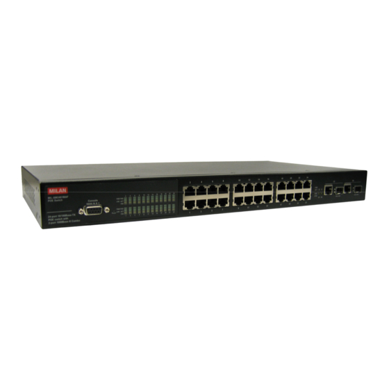
Page 15: Hardware Description
440mmx 280mm x 44mm (Lx W x H) Front Panel The front panel of the 24 10/100TX plus 2 SFP/Copper managed POE switch consists of 24x 10/100Base-TX RJ-45 ports (Auto MDI/MDIX), 2 auto detect Giga ports, and one console port. The LED Indicators are also located on the front panel of the Switch. - Page 16 LED statuses and meaning. Power LNK/ACT LED indicators Status Description Green Power On Power is not connected Green The port is connecting with the device. The port is receiving or transmitting Blinks data. No device attached. The port is operating in Full-duplex Orange mode.
- Page 17 Green Power Forwarding 1000(Giga port) Green 25 & 26 port 100(Giga port) Orange 25 & 26 port Green LNK/ACT (Giga port) Blink 25 & 26 port Orange FDX/COL (Giga port) Blink 25 & 26 port The POE Injector function is on and power is forwarding the attached PD device.
-
Page 18: Rear Panel
Make sure mounting surface on the bottom of the switch is grease and dust free. Remove adhesive backing from your rubber feet. C. Apply the rubber feet to each corner on the bottom of the switch. These footpads can prevent the switch from shock/vibration. -
Page 19: Power On
[Note] For proper ventilation, allow about at least 4 inches (10 cm) of clearance on the front and 3.4 inches (8 cm) on the back of the Switch. This is especially important for enclosed rack installation. Power On Connect the power cord to the power socket on the rear panel of the Switch. -
Page 20: Network Application
24 10/100TX plus 2 SFP/Copper managed POE switch. By using Uplink port, the Switch can connect with another switch or hub to interconnect other small-switched workgroups to form a larger switched network. Meanwhile, you can also use fiber ports to connect switches. -
Page 21: Segment Workgroup
The 24 10/100TX plus 2 SFP/Copper managed POE switch has POE injector function on each Ethernet port that can provide the power to the PD device, such as AP or switch. It can solve the problem of the PD device position limitation for power supply. The following figure is an example of network application for Power over Ethernet application. -
Page 22: Dc Power Input
The AC power and the DC 48V power can be connected at the same time, but the switch will use the DC 48V as the master power input and the AC power as the secondary or backup power input. The following figures are example of the application. In the figure, the DC 48V power input connects with the power supply device and through the RS-232 connection to manage the connected power supply device. -
Page 24: Power Redundant
Power Redundant The 24 10/100TX plus one Exp. slot managed POE Switch can connect with UPS to prevent the power failure. - Page 25 Power Redundant Application...
-
Page 26: Console Management
Login in the Console Interface When the connection between Switch and PC is ready, turn on the PC and run a terminal emulation program or Hyper Terminal and configure its communication parameters to match the following default characteristics of the console port:... -
Page 27: Cli Management
Enter key to bring out the login prompt. Key in the “root“(default value) for the both User name and Password (use Enter key to switch), then press Enter key and the Main Menu of console management appears. Please see below figure for login screen. - Page 28 The privileged command is advance mode Privileged this mode to • Display advance function status • Save configures Use this mode to configure parameters that apply to your switch as a whole. Use this mode to configure VLAN-specific parameters.
-
Page 29: Commands Set List
EXEC mode, enter exit Description Set switch system name string Use this mode to configure parameters for the switch and Ethernet ports. Use this mode to UPS parameters for the switch. Use this mode to POE parameters for the switch. - Page 30 Set switch system contact window string Use the ip address interface configuration command to set an IP address for a switch. Use the no form of this command to remove an IP address or to disable IP processing. The “write memory” is save configuration and the “write...
- Page 31 Restore to default Changes a login username. (maximum 10 words) Specifies a password (maximum 10 words) Show username & password Show system information Switch (config)# default Switch (config)# username xxxxxx Switch (config)# password xxxxxx Switch# show accounting Username: root Password: root Switch>...
-
Page 32: Port Commands Set
Description Defaults Use the fast Ethernet interface configuration command Use the module Ethernet interface configuration command Switch# show ip address ip: 192.168.1.1 Address subnet: 255.255.255.0 Address gateway: 192.168.1.254 Switch> show version Firmware version: 1.0 Hardware version: 3.0... - Page 33 Ethernet. Use the speed configuration command to specify the speed mode of operation for module Ethernet. The 100Base-FX module only supported for speed Switch (config)# interface fastEthernet 0/1 Switch (config-if)# duplex full Switch (config)# interface moduleEthernet Switch (config-if)# duplex full...
- Page 34 Use the priority configuration command on Ethernet ports. Disable Use the no form of this command to disable security on the port. Switch (config)# interface fastEthernet 0/1 Switch (config-if)# flowcontrol on Switch (config)# interface fastEthernet 0/1 Switch (config-if)#...
- Page 35 Enable operation for Ethernet ports. Use the disable form of this command to disable the port. show interface configuration status Switch (config)# interface fastEthernet 0/1 Switch (config-if)# bandwidth in 50 Switch (config)# interface fastEthernet 0/1 Switch (config-if)#...
-
Page 36: Trunk Commands Set
Display the bandwidth of the values Use the fast Ethernet interface configuration command Description Defaults Switch (config)# interface fastEthernet 0/1 Switch (config-if)# show interface status Switch (config)# interface fastEthernet 0/1 Switch (config-if)# show interface... - Page 37 Add trunking group. Use the no form of Disable this command to delete trunking group. Set trunking group port active Switch # show group 1 Group Trunk.1: Ports: 02 03 04 Priority: 0001 Lacp: Enable Work ports: 0 LACP: Switch (config)#...
-
Page 38: Vlan Commands Set
[port ID] mode Description Defaults To enter the VLAN configuration interface To set switch VLAN mode .Use the no form of this Disable command to restore to default. Port Base VLAN Add new Port Base VLAN Delete port base... - Page 39 Remove the port from its port group. Delete 802.1Q VLAN group Add protocol vlan [group name]: vlan group name Switch (vlan)# vlan v2 delete 5 Switch(vlan)# vlan v2 vlanid 2 port 1-4 tag 2-4 Switch(vlan)# vlan v2 add 5-8 tagged...
- Page 40 X.75 internet-x75 X.25 Layer3-x25 [VLAN ID]: 2 ~ 4094 [port ID]: port ID 1~10 Set VLAN ID range [1~255] range 0 Switch(vlan)# vlan protocol v3 arp vlanid 2 port 5-8 tag 6,8 Switch(vlan)# vlan protocol v3 banyan vlanid 2 port 5-8...
- Page 41 [1792~2047] range [2048~2303] range [2304~2559] range [2560~2815] range [2816~3071] range [3072~3327] range [3328~3583] range [3584~3839] range [3840~4094] range Set the port of some port group tagged or untagged OLD: 0 NEW: 2 Switch (vlan)# vlan protocol v2 add 5 tagged...
- Page 42 1 ~ 4094 show protocol vlan Protocol netbios Set Port PVID and Ingress Filter Rules1 & Ingress Filter Rules2 Switch (vlan)# vlan protocol v2 delete Switch (vlan)# show vlan v2 2 Switch (vlan)# show vlan protocol Switch (vlan)# port 2 pvid 2...
-
Page 43: Spanning Tree Commands Set
Port PVID and Ingress Filter Rules1 & Ingress Filter Rules2 Description Defaults Display a summary of the spanning-tree states. Switch (vlan)# show port 2 Port ID: 2 Port Vid: 2 Ingress 1 Filter: Disable Ingress 2 Filter: Enable Example Switch>... - Page 44 Use the spanning-tree max-age global configuration command to 20 sec change the interval between messages the spanning tree receives from the root switch. If a Switch (config)# spanning-tree on Switch (config)# no spanning-tree Switch (config)# spanning-tree priority 32767 Switch (config)# spanning-tree...
- Page 45 Global hello-time configuration [seconds] mode switch does not receive a bridge protocol data unit (BPDU) message from the root switch within this interval, it recomputes the Spanning Tree Protocol (STP) topology. Use the no form of this command to return to the default interval.
- Page 46 Use the spanning-tree forward-time global configuration command to set the forwarding-time for 15 sec. the specified spanning-tree instances. The forwarding time determines how Switch (config)# interface fastEthernet 0/2 Switch (config-if)# stp-path-cost 20 Switch (config)# spanning-tree forward-time 20...
-
Page 47: Qos Commands Set
Use the no form of this command to return to the default value. Description Defaults Switch (config)# interface... - Page 48 Use the no form of this command to restore to default. 0~3 LOW [Priority] 0~7 4~7 HI 0~3 LOW [Priority] 0~7 4~7 HI Switch (config)# qos storm-control Switch (config)# low-priority-delay -bound on 1 Switch (config)# qos level 2,3 Switch (config)# no qos level 0-7...
- Page 49 Set qos bridge delay bound Use the no form of this command to restore to default. Show broadcast storm control. WRR: Switch (config)# qos queuepolicy wrr hi 7 low 1 First Come First Served: Switch (config)# qos queuepolicy fcfs All High before...
-
Page 50: Igmp Commands Set
Switch (config)# show qos policy Qos Mode: WRR Switch (config)# show qos low-priority-delay -bound Qos low priority delay bound: 1 Switch (config)# show qos bridge-delay-bou bridge-delay-bound Example Switch (config)# igmp on Switch (config)# igmp-query enable Switch# show ip igmp profile... -
Page 51: Mac / Filter Table Commands Set
Use the no form of this command to use the default aging-time interval. The aging time applies to all VLANs. VID Port 224.1.1.1 10 1,2,6 Example Switch (config)# mac-address-table aging-time on Switch (config)# mac-address-table aging-time 333 (Disable) Switch (config)# mac-address-table... - Page 52 Switch (config)# interface fastEthernet 0/2 Switch (config-if)# mac-address-table static hwaddr 004063112233 vlanid 10 Switch (config)# interface fastEthernet 0/2 Switch (config-if)# mac-address-table static hwaddr 004063112233 vlanid 10 Switch # show mac-address-table static Switch# show mac-address-table aging-time MAC Address...
- Page 53 the MAC address aging-time: 300 table.
-
Page 54: Snmp Commands Set
Use the no form of PUBLIC this command to remove the specified community. Configure SNMP server host information and community string Example Switch (config)# snmp system-name l2switch Switch (config)# snmp system-location lab Switch (config)# snmp system-contact where Switch (config)# snmp... -
Page 55: Port Mirroring Commands Set
Use the no form of this command to return the port to its default value. Switch(config)# no snmp-server host 192.168.1.50 community public Switch (config)# snmp system-name l2switch Example Switch (config)# Interface fastEthernet Switch (config-if)# port monitor both 3... -
Page 56: 802.1X Commands Set
Use the 802.1x global configuration command to enable 802.1x Disable protocols. Use the no form of the command to restore to default Switch # show port monitor State: Enable AnalysisPortId: 8 Port 01 TxRx: Monitor Port 02 TxRx: Port 03 TxRx:... - Page 57 Use the no form of this command to return to the default interval. set radius server port set accounting port set NAS ID Switch (config)# 8021x system radiusip 192.168.1.1 192.16 8.16.3 (Default) Switch(config)# no 8021x system...
- Page 58 TX period. Use the no form of this command to return to the default value. Set the period of time the switch wait for a supplicant response to an EAP request. Set the period of time the switch wait for a server response to an authentication request.
- Page 59 Authorized or Unauthorized state in accordance with the outcome of an authentication exchange between the Supplicant and the Switch(config)# 3600 8021x misc reauthperiod 20 Switch (config)# interface fastethernet 0/3 Switch (config-if)# 8021x portstate accept...
-
Page 60: Tftp Commands Set
Disable: The specified port is required to be held in the Authorized state. Description Defaults Backup configure file command Restore configure file command Update firmware command Example Switch (config)# copy flash:config.text tftp Server IP:192.168.1.1 Image Filename:backup. Switch(config)# Tftp:config.text flash Server IP:192.168.1.1 Image Filename:restore. -
Page 61: Ups Commands Set
UPS status. Show UPS information UPS will perform the self-test for 10 seconds. Description Defaults Server IP:192.168.1.1 Image Filename:image.bi Example Switch (ups)#status Input Output Voltage……. Switch (ups)# info Company Name :xxx Model :xxx Version :xxx Switch (ups)# test10 test OK Example... - Page 62 Enabling or disabling the port POE injected function. Enabling or disabling per port power limit by classification. Enabling or disabling per port power limit by management. Switch(poe)# status Switch(poe)# setpm on Set Power Management Enable Switch(poe)# setlimit 100 Switch(poe)#...
-
Page 63: System Log Commands Set
Set System log server IP address. Enable or disable system log mode Switch(poe)# portleg enable Switch(poe)# portpri critical 2 Switch(poe)# portplm 12200 Example Switch> show systemlog switch# show systemlog Syslog Client: Enable Syslog Server Ip: 192.168.16.2 Switch(config)# systemlog ip 192.168.1.100 Switch(config)# systemlog enable... -
Page 64: Sntp Commands Set
Global sntp ip [IP configuration address] mode sntp Global timezone configuration [value] mode Description Defaults Enable/Disable SNTP. Disable Set SNTP server IP address. Set time zone. Example Switch(config)# sntp enable Switch(config)# sntp disable switch#sntp ip 192.168.16.123 Switch(config)# sntp timezone 8... -
Page 65: Menu Management
“menu” command. You will see the main menu interface. The following configure steps are based on the software kernel version v1.01. Provide a menu line interface to manage and monitor the switch. User can use windows Hyper Terminal program through the console port to connect the switch for configuration. - Page 66 Main menu line interface Control Key description: The control keys provided in all menus: Tab/Backspace: Move the vernier to configure item. Enter: Select item. Space: Toggle selected item to next configure or change the value. Esc: to exit the current action mode.
-
Page 67: Status And Counters
Status and Counters In Status and Counters, you can view Port status, counters, and configure system parameter. Port Status It displays status of each port. Select the <Previous Page> action to display previous page. And, select the <Next page> action to display next page. Type: display port connection speed. -
Page 68: Port Counters
BP: display backpressure status. display bandwidth In/out control status. Bandwidth In/Out: Priority: display the port priority status. Security: display the port security status. Port Counters It displays the current port counter information. Select the <Refresh> to get newest counter information. Select <Clear> to set all ports counter to 0. Select <Next Page> to go to next page. -
Page 69: System Information
• System Name: the name of device. • System Location: where the device is located. • System Description: the name of device type. • Firmware Version: the switch’s firmware version. • Hardware Version: the switch’s Hardware version. • Kernel Version: the system kernel software version. - Page 70 System Information interface...
-
Page 71: Switch Configuration
Switch Configuration In Switch Configuration, it has 8 main functions – Administration, Port, Trunk, Port Mirroring, VLAN, Priority, MAC Address, and Misc Configuration. Under each function, there are more sub-functions. We will describe in following paragraph. Switch Configuration interface Administration Configuration In Administration Configuration, you can configuration system parameter, IP, login username, password, and SNTP configuration. - Page 72 Device Information You can configure the device information. Select <Edit> action to configure. Name: assign the name for the switch. Description: a short description for the switch. Location: the switch location, ex: Taipei. Contact: the contact person or information. Select <Apply> action to apply the configuration.
- Page 73 DHCP will not effective and the switch will continue using the manually entered static IP. If you have changed the switch to a static IP address, you can set the IP address back to its default IP address or you can reset the switch back to factory default. And then you can enable the DHCP client function to work.
- Page 74 IP Configuration interface User Name Configuration You can change the console and web management login user name. 1. Select the <Edit> 2. Enter the new user name 3. Select the <Apply>...
- Page 75 User Name Configuration interface Password Configuration You can change the console and web management login password. 1. Select the <Edit> 2. Old Password: enter the old password. 3. New Password: enter the new password. 4. Enter Again: reenter the new password for confirmation. 5.
-
Page 76: Sntp Configuration
SNTP Configuration You can configure the SNTP (Simple Network Time Protocol) settings. The SNTP allows you to synchronize switch clocks in the Internet. SNTP Client: enable or disable SNTP function to get the time from the SNTP server. UTC Timezone: set the switch location time zone. -
Page 77: System Log Client Configuration
System log Client Configuration You can configure the switch as the system log client that can view the system log information that from the system log server that you have assigned. Select <Edit> Client Mode: enabling or disabling the system log client function. “Enable” can view the system log information from the assigned system log server. -
Page 78: Port Configuration
Port Configuration You can set up every port status. Select <Edit> Use “Tab/Backspace” key to move between items. Type: display port connection speed. State: Current port status. The port can be set to disable or enable mode. If the port setting is disable then will not receive or transmit any packet. -
Page 79: Trunk Configuration
Port Configuration interface Trunk Configuration You can configure port trunk group. 1. Select <Edit> 2. Using “Tab” key move to the port that want to be added as trunk group. 3. Using “Space” key to mark the port. 4. Using Tab key move to Trunk # (ex. Trunk1, Trunk2…) to change the Trunk # value to Static, LACP, or Disable. -
Page 80: Port Mirroring Configuration
Port Mirroring Configuration The port mirroring is a method for monitor traffic of switched networks. The specific port can monitor traffic through the mirror ports. The monitored ports in or out traffic will be duplicated into monitoring port. 1. Select the <Edit> 2. - Page 81 3. Analysis port: Set the destination port of mirroring packet. All of the packets of mirroring port will be duplicated and sent to Analysis port. 4. Port State: Select the ports that want to be mirrored. 5. Use “Space” key to mark the mirroring port can. 6.
-
Page 82: Vlan Configuration
VLAN Configuration You can configure VLAN group in VLAN Configuration. There are four functions in VLAN Configuration mode: VLAN Configuration, Create a VLAN Group, Edit/Delete VLAN Group and Group Sorted Mode. Follow the below description to configure VLAN. VLAN Configure Before starting to configure VLAN, you must select the VLAN mode in VLAN Configure function. - Page 83 “Space” key to choose “forward” or “drop” the frame that VID not matching this port’s configured VID. 3. Select <Apply> to apply the configuration. [Note] when the VLAN mode changed that user has to restart the switch for valid value. Create VLAN Group Create Port-Based VLAN Select <Edit>.
- Page 84 When you select to enable security VLAN group, only the members in this VLAN group can access to the switch. The steps of setting security VLAN refer to the following step 2~ 8. After you configured the security VLAN group, you can continue to create other VLAN groups.
- Page 85 Select <Edit>. VLAN Name: Type a name for the new VLAN, ex: VLAN01. VLAN ID: Type a VID. The default is 1. There are 256 VLAN groups to provided configure. Protocol VLAN: Press “Space” key to choose protocols type. Member: Press “Space” key to change the member value. Untagged: this port is the member port of this VLAN group and outgoing frames are NO VLAN-Tagged frames.
- Page 86 Edit / Delete VLAN Group User can edit or delete a VLAN group. Select <Edit> or <Delete> action. Select the VLAN group that you want to edit or delete, then press enter. In <Edit> action, user can modify the member port and remove some member ports from this VLAN group.
- Page 87 Group Sorted Mode You can select VLAN groups sorted mode: (1) Name (2) VLAN ID. In the Edit/Delete a VLAN group page will display the result. Select <Edit> Use “Space” key to select the sort mode. Select <Apply> Edit/Delete a VLAN Group interface...
- Page 88 Group Sorted Mode interface...
-
Page 89: Priority Configuration
Qos Mode: User can select the ratio of high priority packets and low priority packets. First Come First Service: the switch will process the packet that is coming first. All High Before low: the packet priority is high will be process before the packet priority is low. -
Page 90: Mac Address Configuration
Priority Configuration interface MAC Address Configuration When you add a static MAC address, it remains in the switch's address table, regardless of whether the device is physically connected to the switch. This saves the switch from having to re-learn a device's MAC address when the disconnected or powered-off device... - Page 91 MAC Address Configuration interface...
- Page 92 Static MAC Address Add the Static MAC Address You can add static MAC address in switch MAC table. Select <Add> <Edit> key to add the static MAC address. MAC Address: Enter the MAC address of the port that should permanently forward traffic, regardless of the device network activity.
- Page 93 Press <Delete> key. Choose the MAC address that you want to delete and then press “Enter”. When pressing “Enter” will complete deletion. Filtering MAC Address You can add, delete, and edit filtering MAC address. Add the Filtering MAC Address Select <Add> <Edit>...
-
Page 94: Misc Configuration
Low Queue Delay Bound: Limit the low priority packets queuing time in switch. If enable, the low priority packet stays in switch exceed Low Queue Max Delay Time, it will be sent. Press Space key to enable or disable this function. - Page 95 Collisions Retry Forever: Disable In half duplex, if happen collision will retry 48 times and then drop frame. Enable – In half duplex, if happen collision will retry forever Hash Algorithm: This Hash Algorithm is for hardware maintain on MAC table calculation.
-
Page 96: Protocol Related Configuration
Protocol Related Configuration You can configure Spanning Tree Protocol, SNMP, LACP, IGMP/GVRP, and 802.1x in Protocol Relate Configuration section. Protocol Relate Configuration interface STP Configuration Spanning tree is a link management protocol that provides path redundancy while preventing undesirable loops in the network. - Page 97 STP Setup You must enable Spanning Tree function before configuration. Select <Edit> Use “Space” key to select the option. Select <Apply>. STP Configuration interface STP Setup interface...
- Page 98 Select <Edit> Priority (0~65535): assign path priority number. Max Age (6~40): the maximum path age Hello Time (1~10): the time that controls switch sends out the BPDU packet to check STP current status. Forward Delay Time (4~30): forward delay time.
-
Page 99: Snmp
On the action menu line you can press <Next Page> to configure rest of ports, press <Previous Page> return to previous page. SNMP To define management stations as trap managers and to enter SNMP community strings. You can also define a name, location, and contact person for the switch. Per Port Setting interface... - Page 100 SNMP System Options Press <Edit>. Name: assign a name for the switch. Contact: Type the name of contact person or organization. Location: Type the location of the switch. Press “ESC” goes back action menu line. Press <Apply> to apply configuration value.
- Page 101 Community Strings Add Community Strings Select <Add> <Edit>. Community Name: type the name of community strings. Write Access: enable the rights is read only or read/write. Read only: Read only, enables requests accompanied by this string to display MIB-object information. Read/Write: Read write, enables requests accompanied by this string to display MIB-object information and to set MIB objects.
- Page 102 Edit SNMP Community Select <Edit> Choose the item that you want to modify and then press “Enter”. Community Name: type the new name. Write Access: Press “Space” key to change the right. Select <Apply>. Delete SNMP Community string Select <Delete>. Choose the community string that you want to delete and then press “Enter”.
-
Page 103: Lacp
If no trap manager is defined, no traps will issue. Create a trap manager by entering the IP address of the station and a community string. Add the trap manager Select <Add> <Edit> to add the trap manager. - Page 104 exchanging information between Partner Systems on a link to allow their Link Aggregation Control instances to reach agreement on the identity of the Link Aggregation Group to which the link belongs, move the link to that Link Aggregation Group, and enable its transmission and reception functions in an orderly manner.
- Page 105 [Note] Before set LACP support, you have to set trunk group on the Trunk Configuration. LACP Working Ports configuration interface LACP State Activity Select <Edit> Use “Space” key to select the Port State Activity. Active: The port automatically sends LACP protocol packets. Passive: The port does not automatically send LACP protocol packets, and responds only if it receives LACP protocol packets from the opposite device.
-
Page 106: Igmp/Gvrp Configuration
LACP State Activity configuration interface LACP Group Status When you setting trunk group, you can see the relation information in here. LACP Group State interface IGMP/GVRP Configuration... -
Page 107: 802.1X Configuration
You can enable or disable the IGMP/GVRP (GARP VLAN Registration Protocol). Select <Edit> Use “Space” key to change the value Select <Apply> 802.1x Configuration You can configure 802.1x relate settings. IGMP/GVRP Configuration interface... - Page 108 802.1x Setup Select <Edit> Use “Space” key to Enable or Disable the 802.1x. Select <Apply> 802.1x Configuration interface...
- Page 109 System Configuration After enabling the IEEE 802.1X function, you can configure the parameters of this function. Select <Edit> Radius Server IP: set the Radius Server IP address. Shared Key: set an encryption key for using during authentication sessions with the specified radius server.
- Page 110 Per Port Setting The State provides Disable, Accept, Reject and Authorize. Use “Space” key change the state value. Reject: the specified port is required to be held in the unauthorized state. Accept: the specified port is required to be held in the Authorized state. Authorized: the specified port is set to the Authorized or Unauthorized state in accordance with the outcome of an authentication exchange between the Supplicant and the authentication server.
- Page 111 Supplicant timeout: set the period of time the switch wait for a supplicant response to an EAP request. Server timeout: set the period of time the switch wait for a server response to an authentication request. Reauthorize Maximum: set the number of authentication that must time-out before authentication fails and the authentication session ends.
- Page 112 802.1x Misc Configuration interface...
-
Page 113: System Reset Configuration
System Reset Configuration System Reset Configuration interface Factory Default Reset switch to default configuration. Press “Y”, switch will load default setting. After finished load default setting, switch will reboot automatically. -
Page 114: System Reboot
Factory Default interface System Reboot Reboot the switch in software reset. All configuration will not change. Power Menu You can view connected UPS information and set command to UPS. - Page 115 UPS information display area UPS information display I/P Volt.: display the current value, minimum, and maximum value of UPS input voltage. O/P Volt.: display the current value, minimum, and maximum value of UPS output voltage. Frequency: display the frequency value of UPS. Bty.
-
Page 116: Poe Menu
You can view POE port information and set command to POE port. Turn on the UPS beeper or turn off the UPS beeper Switch to com1 or com 2 connected UPS Enabling the screen auto refresh Exit the UPS menu mode... - Page 117 Power Supply management Port Enable: displays the POE port status. Y means the port is enabling. N means the port is disabling and will not have any power providing but the port still can transmit the data packet. PwrLimitClass.: displays the power class limit status. N means the power class limit is disabling.
- Page 118 PD still present on this port. It is an IEEE 802.3af operating procedure. R detect: When the port doesn’t connect with any PD, the POE switch will poll each port and detects the resistor.
-
Page 119: Save Configuration
[0] Exit Save Configuration You must save the configuration to the flash memory when you have changed the configuration. Otherwise, the new configuration will be lost when the switch restart or power off. Enabling or disabling per port power output limit. -
Page 120: Xmodem Upgrade
Xmodem Upgrade Before using Xmodem upgrade, disconnect terminal and modify baud rate to 57600bps, then connect again. Press “X” key to start upgrading from Xmodem. You will see the following screen displays. Select “send file" under Transfer menu from menu bar. Select "browse"... - Page 121 After successfully upgraded the new firmware, please modify baud rate to 9600bps.
-
Page 122: Web-Based Management
Preparing for Web Management Before to use web management, you can use console to login the Switch checking the default IP of the Switch. Please refer to Console Management Chapter for console login. If you need change IP address in first time, you can use console mode to modify it. The default value is as below: IP Address: 192.168.1.77... -
Page 123: System Login
Click “Enter” or ”OK”, then the home screen of the Web-based management appears. 24 10/100TX plus 100FX Exp. Slot managed POE switch Web Management Interface Port status In Port status, you can view every port status that depended on user setting and the negotiation result. -
Page 124: View The Port Information
Priority: display the port static priority status is “High” or “Low” or “Disable”. Security: display the port security is “enable” or “disable”. View the Port Information You can direct click the port on the Switch figure on the top of web page. Then, you will see the port information. Port Status interface... -
Page 125: Port Statistics
Port information interface Port Statistics The following information provides a view of the current port statistic information. Scroll down for more ports statistics. Click Clear button to clean all counts. -
Page 126: Administrator
Port Statistics interface Administrator In Administrator function, it provides the following functions -- IP Configuration, Switch Settings, Console Port Information, Port Controls, Trunking, Forwarding and Filtering, VLAN Configuration, Spanning Tree, Port Mirroring, SNMP Management, Security Manager, and 802.1x Configuration. -
Page 127: Ip Address
DHCP will not effective and the switch will continue using the manually entered static IP. If you have changed the switch to a static IP address, you can set the IP address back to its default IP address or you can reset the switch back to factory default. And then you can enable the DHCP client function to work. -
Page 128: Basic
In Switch setting, it has three parts of setting – Basic, Advance, and Misc Config. We will describe the configure detail in following. Basic In Basic switch setting, it displays the switch basic information. System Name: the name of switch. - Page 129 1sec, 2 sec, 4 sec and off. Enable Low Queue Delay Bound: limit the low priority packets queuing time in switch. If the low priority packet stays in switch exceed Max Delay Time, it will be sent. The valid range is 1~255 ms.
- Page 130 For example, 5 High: 1 Low means that the switch sends 5 high priority packets before sending 1 low priority packet. Qos Policy (checked for High Priority): 0~7 priority level can map to high or...
-
Page 131: Misc Configuration
IGMP Query Mode: recognizes different queries from clients or servers to decide which Query will be the first priority. The modes are: Auto Mode: chooses the switch that has the smallest IP address to be set for the IGMP Query mode. -
Page 132: Console Port Information
Console Port Information Console is a standard UART interface to communicate with Serial Port. User can use windows HyperTerminal program to link the switch. Please refer to Console Management Console login for detail steps. Console port information shows as follow:... - Page 133 Band Width: The port1 ~ port 26, supports port ingress and egress rate control. For example, assume port 1 is 10Mbps, users can set it’s effective egress rate is 1Mbps, ingress rate is 500Kbps. The switch will perform flow control or Back Pressure to confine the ingress rate to meet the specified rate.
-
Page 134: Trunking
IEEE 802.3ad. Aggregator setting System Priority: a value used to identify the active LACP. The switch with the lowest value has the highest priority and is selected as the active LACP. Group ID: There are seven trunk groups to provided configure. Choose the "Group ID"... -
Page 135: Aggregator Information
Click Apply Delete button to delete Trunk Group. Select the Group ID and click button. Aggregator Information When you had setup the LACP aggregator, you will see relation information in here. Trunking – Aggregator Information interface Trunking—Aggregator Setting interface Delete... -
Page 136: Aggregator State Activity
Aggregator State Activity When you had setup the LACP aggregator, you can configure port state activity. You can mark or un-mark the port. When you mark the port and click activity will change to Active. Opposite is Passive. Active: The port automatically sends LACP protocol packets. Passive: The port does not automatically send LACP protocol packets, and responds only if it receives LACP protocol packets from the opposite device. -
Page 137: Forwarding And Filtering
Protocol (IP) suite. IP manages multicast traffic by using switches, routers, and hosts that support IGMP. Enabling IGMP allows the ports to detect IGMP queries and report packets and manage IP multicast traffic through the switch. IGMP have three fundamental types of message as follows:... - Page 138 Message A message sent from the querier (IGMP router or switch) Query asking for a response from each host belonging to the multicast group. A message sent by a host to the querier to indicate that the host wants to be or is a member of a given group indicated in Report the report message.
-
Page 139: Static Mac Address
Static MAC Address When you add a static MAC address, it remains in the switch's address table, regardless of whether the device is physically connected to the switch. This saves the switch from having to re-learn a device's MAC address when the disconnected or powered-off device is active on the network again. -
Page 140: Vlan Configuration
In MAC Address box, enter the MAC address that wants to filter. VLAN ID: If tag-based (802.1Q) VLAN are set up on the switch, in the VLAN ID box, type the VID to associate with the MAC address. - Page 141 VLAN members. Basically, creating a VLAN from a switch is logically equivalent of reconnecting a group of network devices to another Layer 2 switch. However, all the network devices are still plug into the same switch physically. The switch supports port-based, 802.1Q (tagged-based) and protocol-base VLAN in web management page.
- Page 142 Port-based VLAN Packets can go among only members of the same VLAN group. Note all unselected ports are treated as belonging to another single VLAN. If the port-based VLAN enabled, the VLAN-tagging is ignored. In order for an end station to send packets to different VLANs, it itself has to be either capable of tagging packets it sends with VLAN tags or attached to a VLAN-aware bridge that is capable of classifying and tagging the packet with different VLAN ID based on not only default PVID but also other information about the packet, such as the protocol.
- Page 143 Enter the VLAN name, VLAN ID and select the members for the VLAN group. Click Apply VLAN—PortBase Add interface...
-
Page 144: 802.1Q Vlan
Tagged-based VLAN is an IEEE 802.1Q specification standard. Therefore, it is possible to create a VLAN across devices from different switch venders. IEEE 802.1Q VLAN uses a technique to insert a “tag” into the Ethernet frames. Tag contains a VLAN Identifier (VID) that indicates the VLAN numbers. - Page 145 GVRP allows automatic VLAN configuration between the switch and nodes. If the switch is connected to a device with GVRP enabled, you can send a GVRP request using the VID of a VLAN defined on the switch; the switch will automatically add that device to the existing VLAN.
- Page 146 Protocol VLAN: choose the protocol type. Default is NONE. From the Available ports box, select ports to add to the switch and click If the trunk groups exist, you can see it in here (ex: TRK1, TRK2…), and you can configure it is the member of the VLAN or not.
- Page 147 Click Next . Then you will see the page as follow.
- Page 148 This feature is useful for accommodating devices that you want to participate in the VLAN but that don’t support tagging. The switch each port allows user to set one VLAN ID, the range is 1~255, default VLAN ID is 1. The VLAN ID must as same as the VLAN ID that the port belong to VLAN group, or the untagged traffic will be dropped.
-
Page 149: Spanning Tree
Acceptable Frame type: ALL: Acceptable all Packet Tag Only: Only packet with match VLAN ID can be permission to go through the port. Click Apply Spanning Tree The Spanning-Tree Protocol (STP) is a standardized method (IEEE 802.1d) for avoiding loops in switched networks. When STP enabled, to ensure that only one path at a time is active between any two nodes on the network. -
Page 150: System Configuration
You can modify STP state. After modification, click Priority: assign path priority number. Max Age: the maximum path age Hello Time: the time that controls switch sends out the BPDU packet to check STP current status. Forward Delay Time: forward delay time. -
Page 151: Per Port Configuration
Per Port Configuration You can configure path cost and priority of every port. Select the port in Port column. Assign the Path Cost. The value range is from 1 to 65535. Assign the port priority value. The value range is from 0 to 255. The lowest value has higher priority. -
Page 152: Port Mirroring
SPT – Per Port Configuration interface Port Mirroring The Port mirroring is a method for monitor traffic in switched networks. Traffic through ports can be monitored by one specific port. That is, traffic goes in or out monitored ports... - Page 153 Monitor Port: the ports you want to monitor. All monitor port traffic will be copied to mirror port. You can select max 25 monitor ports in the switch. User can choose which port want to monitor in only one mirror mode.
-
Page 154: Snmp Management
Prot Mirroring interface SNMP Management The SNMP is a Protocol that governs the transfer of information between management and agent. The switch supports SNMP V1. - Page 155 You can define management stations as trap managers and to enter SNMP community strings. You also can define a name, location, and contact person for the switch. Fill in the system options data, and then click Apply to update the changes.
-
Page 156: Security Manager
A trap manager is a management station that receives traps, the system alerts generated by the switch. If no trap manager is defined, no traps will issue. Create a trap manager by entering the IP address of the station and a community string. -
Page 157: Sntp Configuration
SNTP Configuration You can configure the SNTP (Simple Network Time Protocol) settings. The SNTP allows you to synchronize switch clocks in the Internet. SNTP Client: enable or disable SNTP function to get the time from the SNTP server. UTC Timezone: set the switch location time zone. -
Page 158: Per Port Configuration
Server Port: set the UDP destination port for authentication requests to the specified Radius Server. Accounting Port: set the UDP destination port for accounting requests to the specified Radius Server. Shared Key: set an encryption key for use during authentication sessions with the specified radius server. -
Page 159: Misc Configuration
Supplicant and the authentication server. Disable: The specified port is required to be held in the Authorized state. Click Apply You can see the every port Authorization information list in table. 802.1x Configuration – Per Port Configuration Misc Configuration Quiet period: Set the period during which the port doesn’t try to acquire a supplicant. TX period: Set the period the port waits to retransmit next EAPOL PDU during an... -
Page 160: System Log
Supplicant timeout: Set the period of time the switch waits for a supplicant response to an EAP request. Server timeout: Set the period of time the switch waits for a server response to an authentication request. Max requests: Set the number of authentication that must time-out before authentication fails and the authentication session ends. -
Page 161: Save Configuration
Save Configuration You must save the configuration to the flash memory when you have changed the configuration. Otherwise, the new configuration will be lost when the switch restart or power off. Click the button to save the configuration to the flash Save Configuration memory. -
Page 162: Tftp Update Firmware
TFTP Update Firmware It provides the functions to allow a user to update the switch firmware. Before updating, make sure you have your TFTP server ready and the firmware image is on the TFTP server. TFTP Server IP Address: fill in your TFTP server IP. -
Page 163: Tftp Restore Configuration
Click Apply TFTP Backup Configuration You can save current EEPROM value from the switch to TFTP server, then go to the TFTP restore configuration page to restore the EEPROM value. TFTP Server IP Address: fill in the TFTP server IP. -
Page 164: Factory Default
Factory Default Reset Switch to default configuration, default value to as following configuration: fi Default IP address: 192.168.1.77 fi Default Gateway: 192.168.1.254 fi Subnet mask: 255.255.255.0 fi The other setting value is back to disable or none. fi Click button to reset switch to default setting. -
Page 165: Power Status
You can view connected UPS information and set command to UPS. UPS information: the information will be available when the UPS is connected with switch and the connection is normal and UPS is power on status. Click button to get the newest information. -
Page 166: Poe Status
Output Voltage: display the current value, minimum, and maximum value of UPS output voltage. Frequency: display the frequency value of UPS. Battery Capacity: display the battery capacity of UPS. UPS Overload: display the overload capacity of UPS. Temperature: display the current temperature of UPS. RatVoltage: range of the UPS voltage. - Page 167 IEEE 802.3af standard their unique electrical signatures in order for the PoE switch can provide the power to those PD devices. Priority: Set port priority for the POE power management. 1 = C (critical), 2 = H...
- Page 168 PD still present on this port. It is an IEEE 802.3af operating procedure. R detect: When the port doesn’t connect with any PD, the POE switch will poll each port and detects the resistor.
-
Page 169: Troubleshooting
2 SFP/Copper managed POE switch. Incorrect connections The switch port can auto detect straight or crossover cable when you link switch with other Ethernet device. For the RJ-45 connector should use correct UTP or STP cable, 10/100Mbps port use 2 pairs twisted cable. If the RJ-45 connector is not correct pin on right position then the link will fail. -
Page 170: Improper Network Topologies
IF the power indicator does turn on when the power cord is plugged in, you may have a problem with power outlet, or power cord. However, if the Switch powers off after running for a while check for loose power connections, power losses or surges at power outlet. IF you still cannot resolve the problem, contact your local dealer for assistance. - Page 171 make sure the power pair it uses. The following table is the signal power pair RJ-45 port pinout. When the PD device pin out is in MDI mode without bridge circuit function, please use the crossover cable for power and data transmit. Please refer to the above table for the pin out transform.
- Page 172 (VCC-)1 (VCC-)2 (VCC+)3 (VCC+)6 MDI-X 1 (VCC-) 2(VCC-) 3(VCC+) 6(VCC+) MDI w/ bridge circuit...
-
Page 173: Technical Specification
Technical Specification This section provides the specifications of 24 10/100TX plus 2 SFP/Copper managed POE switch, and the following table lists these specifications. Standard LED Indicators Connector IEEE802.3 10BASE-T IEEE802.3u 100BASE-TX/100BASE-FX IEEE802.3z Gigabit SX/LX IEE802.3ab Gigabit 1000T IEEE802.3x Flow Control and Back pressure IEEE802.3ad Port trunk with LACP... - Page 174 Storage Temp. Remote power feeding Power Power consumption One RS-232 DB-9 female connector for switch management and 2 RS-232 DB-9 male connectors on rear side for DC power supply and UPS management. Store and forward switch architecture. Up to 8.8Gbps...
- Page 175 Ventilation Operating environment Storage environment Safety 2 DC Fans with detect function 0 ~40 , 10%~95%RH -40 ~70 , 95% RH FCC Class A, CE UL, cUL, CE/EN60950...
-
Page 176: Appendix
Appendix Console Port Pin Assignments The DB-9 serial port on the front panel is used to connect to the switch for out-of-band console configuration. The console menu-driven configuration program can be accessed from a terminal or a PC running a terminal emulation program. The pin assignments used to connect to the serial port are provided in the following tables. -
Page 177: Cables
5 SGND Cables The RJ-45 ports on the switch support automatic MDI/MDI-X operation, so you can use standard straight-through twisted-pair cables to connect to any other network device (PCs, servers, switches, routers, or hubs). Please refer to the following table for cable specifications. - Page 178 Note: “+” and “-” signs represent the polarity of the wires that make up each wire pair. All ports on this switch support automatic MDI/MDI-X operation, you can use straight-through cables for all network connections to PCs or servers, or to other switches or hubs.
Need help?
Do you have a question about the MIL-SM2401MAF and is the answer not in the manual?
Questions and answers