
Related Manuals for MiLAN MIL-SM800


Summary of Contents for MiLAN MIL-SM800
-
Page 1: User Guide
Managed 8 port 10/100 Switches MIL-SM800 MIL-SM801 with additional fiber port USER GUIDE... - Page 2 EN60950 (IEC950) - Product Safety Five-Year Limited Warranty MiLAN Technology warrants to the original consumer or purchaser that each of it's products, and all components thereof, will be free from defects in material and/or workmanship for a period of five years from the original factory shipment date. Any warranty hereunder is extended to the original consumer or purchaser and is not assignable.
-
Page 3: Table Of Contents
Connecting a Terminal or PC to the Console Port …………..…..…………….. Assigning IP address ……………...………….………..………..…………………. Secured IP ……………………….…..……………………………………………….. Resetting Factory Defaults (MIL-SM801)………….………..………..……… …… Resetting Factory Defaults (MIL-SM800) )………….………..………..…… …… 4. Web-Based Management .………………………………………………. …… …… . System Login ………………………..……………..…………….……..…………… 5. System Configuration .…………………………………………………… ……………... -
Page 4: Introduction
Computer networks have proven to be one of the fastest methods of communication. The MIL-SM801 and MIL-SM800 series are compact desktop size switches that are ideal solutions for small, medium and enterprise networks. The switch provides wire-speed switching with high-performance, and low-cost connections. -
Page 5: Features
Port Trunking ( Up to 4 ports ---800Mbps cascade ) MIB II ( RFC1213 ) supported Port Configuration Port Disable/Enable Setting Auto-negotiation, 100 Full/half-duplex, or 10 Full/half-duplex mode Package Contents MIL-SM801XX or MIL-SM800 Power cord Four rubber feet RS-232 cable for console port User Guide... -
Page 6: Ethernet Switching Technology
Figure 1-2. Package Contents Compare the contents of your MIL-SM801XX or MIL-SM800 package with the standard checklist above. If any item is missing or damaged, please contact your local dealer for service. Ethernet Switching Technology Ethernet Switching Technology dramatically boosted the total bandwidth of a... -
Page 7: Management Methods
Management Methods The switches support the following management methods: Console and Telnet Management Web-based Management SNMP Network Management Console and Telnet Management Console Management is done through the serial Console Port. This method requires a direct connection between a PC and the switch. Telnet management is done over the network. -
Page 8: Hardware Description
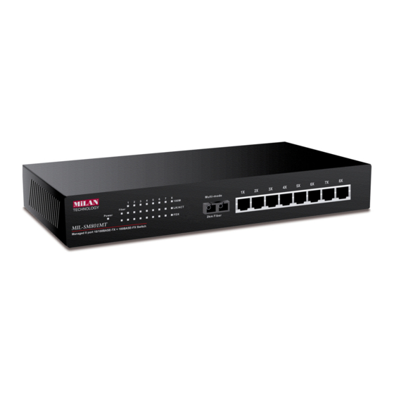
2. Hardware Description This section describes the hardware of the managed switches. The switch is compact in size with eight auto-sensing 10/100Mbps Ethernet RJ-45 ports (MIL-SM800) and one 100Base-FX fiber port (MIL-SM801xx). Front Panel The front panel of the MIL-SM801XX series consists of eight auto-sensing 10/100Mbps Ethernet RJ-45 ports (automatic MDI/MDIX), one 100Base-FX fiber port, and LED indicators. -
Page 9: Mil-Sm801Mt With Mt-Rj Connector
Figure 2-5. The Front Panel of the MIL-SM801XX with MT-RJ connector Figure 2-6. The Front Panel of the MIL-SM801XX with VF-45 connector Figure 2-7. The Front Panel of the MIL-SM800 RJ-45 Ports (Auto MDI/MDIX): Eight 10/100 auto-sensing for 10Base-T or 100Base-TX connections. -
Page 10: Led Indicators
LED Indicators Figure 2-7. Detail of LED Indicators for the MIL-SM801 There are three LED-indicators (100M, LNK/ACT, FDX/COL) for each UTP port. The following table provides descriptions of the LED indicators. They provide a real- time indication of operational status. Status Color Description... -
Page 11: Rear Panel
Rear Panel The 3-pronged power plug is located at the rear panel of the switch as shown in Figure 2-8. The switch will work with AC in the range of 100-240V AC, 50-60Hz. Figure 2-8 The Rear Panel of the switch Desktop Installation Set the switch on a sufficiently large flat space with a power outlet nearby. -
Page 12: Network Configuration
3. Network Configuration This section explains how to configure console management using the console management program. Console management involves the administration of the switch via a direct connection to the RS-232 console port, which has a female DB-9 connector. From the main menu of the console program, user has access to manage the functions of the switch. -
Page 13: Assigning Ip Address
Note: Console program is case sensitive. “ After you have finished setting parameters, press the Enter” Key and the Main Menu of console management appears. Figure 3-3. The Main Menu of Console Management Assigning an IP Address to the switch Once you have logged into the switch, you need to assign an IP address to the switch’s Ethernet interface so that you can connect to the switch using a Web Browser. - Page 14 You will now find that the default IP address has been changed to IP address 192.168.12.40. Reboot by typing “reboot” or “H”. By similar methods, you can configure Subnet Mask (default subnet Mask is 255.255.255.0), Broadcast (default Broadcast is 255.255.255.255), and Gateway (default Gateway is 192.168.1.6).
- Page 15 Figure 4-5. Execute reboot Figure 3-6. After pressing Enter twice, you will find the old IP address has changed into new IP address. Note: After any setting changes, reboot. Use the ping command for verification.
-
Page 16: Secured Ip
Secured IP Secured IP can guard against unauthorized users accessing the switch management. Network security for IP access allows only one IP address or up to 3 IP addresses to access the web based management server and telnet server. The Default Secured IP is 0.0.0.0 for all three secured IP, which means that no network security on IP was set from original factory setting. -
Page 17: Resetting Factory Defaults (Mil-Sm801)
Figure 3-8. After pressing Enter twice, the first secured IP address is set to 199.86.12.46. Resetting Factory Defaults for the MIL-SM801xx You can reset the switch back to factory default settings by using the loaddefault command. Simply type L 2 at the MIL>_ prompt and press enter. Note: If you do not type L 2, and only type L, the following option appears: Usage: loaddefault (0:1:2). -
Page 18: Resetting Factory Defaults (Mil-Sm800) )
Simply type L 2 at the MIL>_ prompt and press enter. Note: If you do not type L 2, and only type L, the following option appears: Usage: loaddefault (0:1:2). The only correct option is L 0 for the MIL-SM800. -
Page 19: Web-Based Management
4. Web-Based Management This section introduces the configuration and functions of the Web-based management for the MIL-SM801XX/MIL-SM800 series. The switch provides an embedded HTML website residing in flash memory. It offers management features and allows users to manage the switch from anywhere on the network through a standard Web Browser. - Page 20 4. Click Login button, then the Password Dialog Box appears. Figure 4-2. The Password Dialogue Box 5. Type in your User Name and Password. (the default is “root” for both.) 6. Click the “OK” button...
-
Page 21: System Configuration
System Configuration After you have started the Web-Based Management you can begin to configure the system. Click System from the Main Menu to display the following screen: Figure 5-1. The System Page The System Page displays information about the switch. Network Setting IP address: 199.86.12.40 Subnet Mask: 255.255.255.0... -
Page 22: Statistics
SysLocation: You can enter the switch physical location. Example: “MiLAN BLDG 10” Statistics The Statistics page displays detailed information for each port. Figure 5-2. The Statistics Page Note: Java must be enabled for statistics information to display. See Appendix settings. -
Page 23: Port Config
Port Configuration You can use the Port Configuration Page to Disable / Enable ports. Figure 5-3. The Port Config Page. In Figure 5-3, the default of each port is Enable. To Disable / Enable any port: 1. Select the drop-down menu in the Status Column. 2. -
Page 24: Speed Config
Speed Config In the Speed Configuration Page, you can configure the speed and duplex of each port. Fig. 5-4. The Speed Config Page To select the speed parameters for a port: Select the drop-down menu in Speed/Duplex Column. Select one of the following 6 Items: Auto/flow control enabled, Auto/flow control disabled, 100Base-Tx/Full Duplex, 100Base-Tx/Half Duplex, 10Base-T/Full Duplex, 10Base-T/Half Duplex. -
Page 25: Vlan
VLANS A LAN was originally defined as a network of computers located within the same area . Today, LANs are defined as a single broadcast domain. This means that if a user broadcasts information on his/her LAN, every user on the LAN will receive the broadcast. -
Page 26: Trunking
Trunking Trunking allows you to create additional bandwidth by aggregating several ports into one single group. Figure 5-6. The Trunking Page From the Trunking page you can click the drop-down menu and select your desired trunk group. You have a choice between a 2-port trunk (ports 1&2) or 4-port trunk (ports 1, 2, 3, &... -
Page 27: Agent Config
Agent Config After clicking the Agent Configuration page, the screen displays the MIL- SM801XX’s current configuration. Refer to the following Agent Configuration page for your own settings. Figure 5-7. The Agent Config Page... -
Page 28: Boot Methods
Boot Methods There are three modes that you can boot your switch in --- FLASH Boot – Boots from a memory chip that software images can be stored, booted, and rewritten as necessary. Flash memory resides in a chip and holds its content without power. -
Page 29: Technical Specifications
Dimensions 250mm x 132mm x 37mm (9.8” x 5.2” x 1.5”) Weight MIL-SM801: 1.08 kg (2.38 lbs) MIL-SM800: 1.06 kg (2.34 lbs) Storage Temp. -40ºC to 70ºC ( -40ºF to 158ºF) Operational Temp. 0ºC to 45ºC ( 32ºF to 113ºF ) -
Page 30: Troubleshooting
7. Troubleshooting This section is intended to help you resolve the most common problems on the MIL- SM801XX series. Incorrect connections Faulty or loose cables Look for loose or obviously faulty connections. Make sure the connections are snug. If that does not correct the problem, try a different cable. Non-standard cables Non-standard or incorrectly pinned cables may cause anything from network collisions to no network connectivity at all. -
Page 31: Appendix Internet Explorer Setting
62.5/125µ multi-mode fiber cable. You can connect two devices up to 2-kilometers. With single-mode fiber use 9/125µ fiber cable for multi-mode as well. You can connect two devices from 15 to ~60- kilometers in full duplex operation. Appendix Browser Settings In order to view all fields when using the MIL-SM801XX Web-based Management with Microsoft’s Internet Explorer you must modify the browser's Java settings. - Page 32 Step 4: Un-check left-bottom box – “Require server verification for all sites this zone”, then click "OK" Step 5: Go back to Internet Options, then click “ Custom Level ” Step 6: Select “ Custom ” under “Java ”...
- Page 33 Step 7: Select: Java - “Custom” Step 8: Select “Edit Permissions” then “Enable” under ”Run Unsigned Content”, then click "OK".
- Page 36 90000382_B...
Need help?
Do you have a question about the MIL-SM800 and is the answer not in the manual?
Questions and answers