
Subscribe to Our Youtube Channel
Related Manuals for MiLAN MIL-SM2401M


Summary of Contents for MiLAN MIL-SM2401M
- Page 1 24 Port 100BASE-TX Plus One Dual Port Module Bay Managed Switch MIL-SM2401M USER GUIDE...
- Page 2 EN60950 (IEC950) - Product Safety Five-Year Limited Warranty MiLAN Technology warrants to the original consumer or purchaser that each of it's products, and all components thereof, will be free from defects in material and/or workmanship for a period of five years from the original factory shipment date. Any warranty hereunder is extended to the original consumer or purchaser and is not assignable.
-
Page 3: Table Of Contents
Table of Contents 1. Introduction Features Intelligent Management Features Package Contents Management Methods Console and Telnet Management Web-based Management SNMP Network Management 2. Hardware Description Front Panel LED Indicators Rear Panel Desktop Installation Rack-mounted Installation Power On 3. Network Application Segment Application Segment Bridge 4. - Page 4 4-3-3. Trunk Configuration 4-3-4. Port Mirroring Configuration 4-3-5. VLAN Configuration 4-3-5-1. VLAN Configure 4-3-5-2. Create a VLAN Group 4-3-5-3. Edit / Delete a VLAN Group 4-3-5-4. Groups Sorted Mode 4-3-6. Priority Configuration 4-3-7. MAC Address Configuration 4-3-7-1. Static MAC Address 4-3-7-2.
- Page 5 4-4-5-4. 802.1X Miscellaneous Configuration 4-5. System Reset Configuration 4-5-1. Factory Default 4-5-2. System Reboot 4-5-3. TFTP Configuration 4-5-3-1. TFTP Update Firmware 4-5-3-2. TFTP Restore Configuration 4-5-3-3. TFTP Backup Configuration 4-6. Xmodem Upgrade 5. Web-Based Management 5-1. System Login 5-2. Port Status 5-3.
- Page 6 5-4-12-1. System Configuration 5-4-12-2. Per Port Configuration 5-4-12-3. 802.1X Miscellaneous Configuration 5-4-13. TFTP Update Firmware 5-4-14. Configuration Backup 5-4-14-1. TFTP Restore Configuration 5-4-14-2. TFTP Backup Configuration 5-4-15. Factory Default 5-4-16. Reboot 6. Troubleshooting Incorrect connections Diagnostic LED Indicators 7. Technical Specifications...
-
Page 7: Introduction
Introduction The MIL-SM2401M managed switch is an ideal solution for applying services at the edge of the network infrastructure. It provides wire-speed, Fast Ethernet switching providing high-performance data transfer. The switch features a store-and-forward architecture with auto-learning of source addresses with an 8K-entry MAC address table. -
Page 8: Features
Features Conforms to IEEE 802.3, 802.3ab, 802.3ad, 802.3u, 802.3z, 802.1d, 802.1p, 802.1Q and 802.3x standard 24 auto-sensing 10/100Mbps Ethernet RJ-45 ports Automatic MDI/MDIX crossover for 10Base-T and 100Base-TX ports One Extension Slot for 2 x100FX, 2 x 1000SX, 1000T+ 1000SX, 2 X 1000T Mbps modules (Optional) N-way Auto-negotiation supported Back-Pressure-Base flow control on Half-duplex link mode Pause-Frame-Base flow control on Full-duplex link mode... -
Page 9: Intelligent Management Features
Intelligent Management Features Web-based management SNMP network management Console and Telnet management Port Based VLAN and IEEE 802.1q Tag VLAN, and VLAN group up to 256, VLAN ID up to 4K IEEE 802.1ad Port Trunk and IEEE 802.3ad Port Trunk with LACP (Link Aggregation Control protocol) supported IEEE 802.1d Spanning Tree MIB II (RFC1213) supported... -
Page 10: Package Contents
User Guide (CD Manual) Warranty Card If any item is missing or damaged, please contact your local dealer for service. Management Methods The MIL-SM2401M switch series support the following management methods: Console and Telnet Management Web-based Management SNMP Network Management Console and Telnet Management Console Management is done through the RS-232 Console Port. -
Page 11: Web-Based Management
Web-based Management The switch provides an embedded HTML web server residing in flash memory. It offers advanced management features and allows users to manage the switch from anywhere on the network through a standard browser such as Microsoft Internet Explorer or Netscape. SNMP Network Management SNMP (Simple Network Management Protocol) provides a means to monitor and control network devices, and to manage configurations,... -
Page 12: Hardware Description
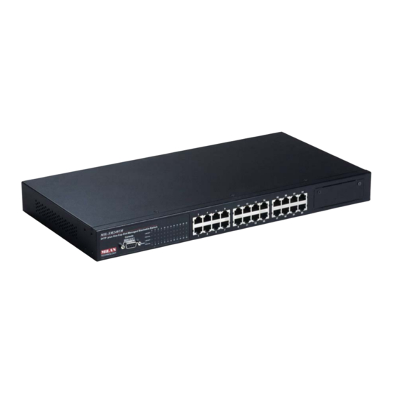
Hardware Description Front Panel The Front Panel of the MIL-SM2401M switch series consists of 24 100Mbps Fast Ethernet ports, one module bay, one console port, one LED-Indicator for Power, and two LED-Indicators (LNK/ACT, FDX/COL) for each UTP port. Console Fast Ethernet Ports... -
Page 13: Led Indicators
LED Indicators The LED Indicators give real-time information of systematic operation status. The following table provides descriptions of LED statuses and their meaning. Figure 2-2. LED indicators Status Description Green Power On. Power Power is not connected. Green The port is connecting with the device. LNK/ACT Blinks The port is receiving or transmitting data. -
Page 14: Rear Panel
Rear Panel The 3-pronged power plug and ventilation fan are located at the rear panel of the MIL-SM2401M as shown in Figure 2-3. The Switch will work with AC in the range 100-240V AC, 50-60Hz On/Off Switch Figure 2-3. The Rear Panel of the MIL-SM2401M Switch... -
Page 15: Desktop Installation
Desktop Installation Set the switch on a sufficiently large flat space with a power outlet nearby. The surface where you put your switch should be clean, smooth, level, and sturdy. Provide enough clearance around the switch to allow attachment of cables, power cord and air circulation. Attaching Rubber Feet A. -
Page 16: Rack-Mounted Installation
Rack-mounted Installation The MIL-SM2401 comes with a rack-mounted kit and can be mounted in an EIA standard size, 19-inch rack. The Switch can be placed in a wiring closet with other equipment. Perform the following steps to rack mount the switch: A. -
Page 17: Power On
Secure the Switch to the rack with a screwdriver and the rack-mounting screws. Figure 2-5. Mount the MIL-SM2401M in an EIA standard 19-inch Rack Note: For proper ventilation, allow at least 4 inches (10 cm) of clearance on the front and 3.4 inches (8 cm) on the back of the Switch. -
Page 18: Network Application
You can use the optional Fiber ports in the dual port module bay of the MIL-SM2401M to connect with another Switch or Hub to interconnect each of your small, switched workgroups to form a larger and long distance switched network. Figure 3-1. Use the MIL-SM2401M switch ports to connect multiple devices in the segment. -
Page 19: Segment Bridge
In the illustration below, two Ethernet switches with PCs and print server, and a local server are connected to the MIL-SM2401M. The devices in this network can communicate with each other through the MIL- SM2401M. -
Page 20: Network Configuration
Network Configuration Connecting a Terminal or PC to the Console Port Console management involves the administration of the switch via a direct connection to the RS-232 console port. This port is a female DB-9 connector. From the main menu of the console program, the user has access to manage the functions of the switch. - Page 21 After the connection between Switch and PC is finished, turn on the PC and run a terminal emulation program or Hyper Terminal to match the following default characteristics of the console port: Baud Rate: 9600 bps Data Bits: 8 Parity: none Stop Bits: 1 Flow Control: None Figure 4-2.
-
Page 22: Console - Menu
Console – Menu 1. The switch also provides a serial interface to manage and monitor the switch. The user can follow the Console Port Information provided by the web to use the Windows HyperTerminal program to link the switch. 2. Type the user name and password to login. The default user name is root;... -
Page 23: Main Menu
4-1. Main Menu There are five items for selection as follows: Status and Counters: Show the status of the switch. Switch Static Configuration: Menus to configure the switch. Protocol Related Configuration: Configures the protocol features. Reboot Switch: Restarts the system or resets switch to the default configuration. Logout: Exits the menu line program. -
Page 24: Status And Counters
4-2. Status and Counters Press the Tab or Backspace key to choose an action item, and then press Enter key to select the item. -
Page 25: Port Status
4-2-1. Port Status Type: Displays the port type of either 100Mbps or 1000Mbps. Link: Displays the port's link. “Down” the port has no link, and “Up” the port has a link with the remote device. State: A port that is enabled will be displayed as “Enable”. A port that is disabled will be displayed as “Disable”. - Page 26 Security: Indicates whether or not source MAC address based traffic filtering is enabled on the port. Actions-> Press the Tab or Backspace key to choose action menu, and then press the Enter key to select the item. <Previous Page>: Displays previous page. <Next page>: Displays next page.
-
Page 27: Port Counters
4-2-2. Port Counters The following information provides a view of the current status of the unit. Select Refresh to view updated statistics or select Clear to reset all counters to 0. Actions-> Press the Tab or Backspace key to choose action menu, and then press the Enter key to select item. -
Page 28: System Information
4-2-3. System Information System Description: Displays the name of device. MAC Address: The unique hardware address assigned by manufacturer. Firmware Version: Displays the switch’s firmware version. Hardware Version: Displays the switch’s hardware version. Module Information: Displays module type and description. Actions->... -
Page 29: Switch Static Configuration
4-3. Switch Static Configuration Press the Tab or Backspace key to choose action menu, and then press the Enter key to select item. - Page 30 4-3-1. Administration Configuration...
-
Page 31: Device Information
4-3-1-1. Device Information Name: 10 characters can be used to give the switch a unique name in order to distinguish it on the network. After configuration this name will show at the top of each menu screen. Description: 32 characters can be used to describe the switch. Location: 32 characters can be used to give a location of the switch. -
Page 32: Ip Configuration
4-3-1-2. IP Configuration This menu enables the user to change the default settings of the IP address, subnet mask and gateway. Rebooting the switch is necessary to have the configuration change take affect. Actions-> <Edit>: Configures all items. When finished, pressing ESC returns to the action menu line. -
Page 33: Change Username
4-3-1-3. Change Username Use this screen to change the User Name. The default user name is root. Actions-> <Edit>: Configures all items. When finished, pressing ESC returns to the action menu line. <Save>: Saves all configured values. <Quit>: Exits the user name configuration page and returns to previous menu. -
Page 34: Change Password
4-3-1-4. Change Password Use this screen to change the Password. The default password is root. Actions-> <Edit>: Configures all items. When finished, pressing ESC returns to the action menu line. <Save>: Saves all configured values. <Quit>: Exits the password configuration page and returns to previous menu. -
Page 35: Port Configuration
4-3-2. Port Configuration This page can change every port status. Press the TAB key to select each item and press the SPACE key to change the configuration of each item. State: Displays current port status. The port can be set to disable or enable mode. - Page 36 Actions-> <Edit>: Configures all items. When finished, pressing ESC returns to the action menu line. <Save>: Saves all configured values. <Previous Page>: Displays previous page. <Next page>: Displays next page. <Quit>: Exits the port configuration page and returns to previous menu.
-
Page 37: Trunk Configuration
4-3-3. Trunk Configuration This page can configure trunk groups. Press the TAB key to select each item and press the SPACE key to change the configuration of each item. Actions-> <Edit>: Configures all items. When finished, pressing ESC returns to the action menu line. -
Page 38: Port Mirroring Configuration
4-3-4. Port Mirroring Configuration Port mirroring is a method for monitoring traffic in switched networks. Traffic through ports can be monitored by one specific port. The traffic being received or transmitted by the monitored ports will be duplicated into the monitoring port. -
Page 39: Vlan Configuration
4-3-5. VLAN Configuration This page can set VLAN mode to port-based VLAN, 802.1Q VLAN or disable VLAN function. All ports are automatically placed in VLAN 1, the default VLAN. To create new VLANs, use the Create a VLAN Group menu and add a VLAN. Make sure when you enter a VLAN name you do not leave spaces. -
Page 40: Vlan Configure
4-3-5-1. VLAN Configure Choose a VLAN In the VLAN Configure menu select the type of VLAN you want to configure: VLAN Disabled (default), Port Based VLAN, or IRRR802.1Q Tag based VLAN. Save the There are 3 different options for VLANs to choose from using configuration. - Page 41 Ingress Filter 1: If this is set, the port will only forward packets with VID (VLAN ID) matching this port’s configured VID. Press the Space key to choose forward or drop the frame with the VID not matching this port’s configured VID.
-
Page 42: Create A Vlan Group
4-3-5-2. Create a VLAN Group Create Port-Based VLAN Select <Edit> to create a port-based VLAN and add member/nonmember ports to using 15 alphanumeric 1. VLAN Name: Type a name for the new VLAN characters and no spaces. 2. Group ID: Type the VLAN group ID. The group ID range is 1~4096. 3. - Page 43 Create 802.1Q VLAN Select <Edit> to create a 802.1Q VLAN and add tagged /untagged member ports to it. using 15 alphanumeric 1. VLAN Name: Type a name for the new VLAN characters and no spaces. 2. VLAN ID: Type a VID (between 1~4096). The default is 1. There are 256 VLAN groups provided to configure.
-
Page 44: Edit / Delete A Vlan Group
4-3-5-3. Edit / Delete a VLAN Group Use this menu to edit or delete a VLAN group. When editing the chosen VLAN, the user can change the protocol VLAN or a member port. A new protocol can be configured and the ports can be changed to tagged or untagged or deleted as member ports from this VLAN. - Page 45 Actions-> <Edit>: Configures all items. When finished, pressing ESC returns to the action menu line. <Delete>: Deletes selected VLAN Groups. <Previous Page>: Displays previous page. <Next page>: Displays next page. <Quit>: Exits this page and returns to previous menu.
-
Page 46: Groups Sorted Mode
4-3-5-4. Groups Sorted Mode Use this menu to select the VLAN groups sorted mode. There are two selections: Name: Sorted by name VID: Sorted by VID The results can be viewed on the Edit/Delete a VLAN Group screen. Actions-> <Edit>: Configures all items. When finished, pressing ESC returns to the action menu line. -
Page 47: Priority Configuration
4-3-6. Priority Configuration Level (0-7): There are eight (0 to 7) priority levels that can be mapped as high or low priority queues. QoS Mode: User can select the ratio of high priority packets and low priority packets by pressing the Space key. High Low Queue service ratio: 1:1, 2:1, 3:1, 4:1, 5:1, 6:1, 7:1, FIFO, H First In First Out (FIFO): The sequence of packets sent depends on arrival order. - Page 48 4-3-7. MAC Address Configuration...
-
Page 49: Mac Address Configuration
4-3-7-1. Static MAC Address When a static MAC address is added, it remains in the switch's address table, regardless of whether the device is physically connected to the switch. This saves the switch from having to re-learn a device's MAC address when the device is disconnected or powered-off and then becomes active again. - Page 50 Edit static MAC address 1. Press <Edit> key to modify a static MAC address. 2. Choose the MAC address that you want to modify and then press enter. 3. Press the <Edit> key to modify all the items. 4. Press ESC to go back action menu line, and then select <Save> to save all configured values.
-
Page 51: Filtering Mac Address
4-3-7-2. Filtering MAC Address Edit Filtering MAC address 1. Press the <Edit> key to modify a static Filtering address. 2. Choose the MAC address that you want to modify and then press enter. 3. Press the <Edit> key to modify all the items. 4. - Page 52 <Delete>: Deletes selected static filtering addresses. <Previous Page>: Displays previous page. <Next page>: Displays next page. <Quit>: Exits this page and returns to previous menu.
-
Page 53: Miscellaneous Configuration
4-3-8. Miscellaneous Configuration Actions-> <Edit>: Configures all items. When finished, pressing ESC returns to the action menu line. <Save>: Saves all configured values. <Quit>: Exits this page and returns to previous menu. 4-3-8-1. MAC Address Ageing Time To configure a different MAC Address Ageing Time, type the number of seconds that an inactive MAC address remains in the switch’s address table before it is deleted. -
Page 54: Broadcast Storm Filtering
4-3-8-2. Broadcast Storm Filtering Broadcast storm filtering is used to limit the amount of broadcast traffic on the network. An excessive amount of broadcast traffic can inhibit data packets from timely delivery. The valid threshold values are 5%, 10%, 15%, 20%, 25% and NO. If the broadcast traffic is greater than the configured value, broadcast packets will be dropped. -
Page 55: Collision Retry Forever
4-3-8-4. Collision Retry Forever Collisions Retry Forever: User can choose to disable collision retry forever and, if a collision occurs in half-duplex mode, the switch will attempt to send the packet 48 times and then drop the frame. When enabled, a collision that occurs in half- duplex mode will result in repeated attempts by the switch forever. -
Page 56: Protocol Related Configuration
4-4. Protocol Related Configuration 4-4-1. STP... -
Page 57: Stp Enable
4-4-1-1. STP Enable This page enables or disables the Spanning Tree function. Press the Space key to select Enabled or Disabled. Actions-> <Edit>: Configures all items. When finished, pressing ESC returns to the action menu line. <Save>: Saves all configured values. <Quit>: Exits this page and returns to previous menu. -
Page 58: Stp System Configuration
4-4-1-2. STP System Configuration All devices in the spanning tree instance will utilize the same values as the root bridge to ensure consistency throughout the network. If this device becomes the root bridge, then the other switches in the STP instance will utilize its values. - Page 59 Hello Time: The number of seconds between the transmission of Spanning- Tree Protocol configuration messages. Enter a number 1 through 10. Forward Delay Time: The number of seconds a port waits before changing from its Spanning-Tree Protocol learning and listening states to the forwarding state.
-
Page 60: Stp Per Port Configuration
4-4-1-3. STP Per Port Configuration State: Spanning tree status for each port is either forwarding or blocking. Specifies the path cost of the port that the switch uses to PathCost: determine which ports are the forwarding ports. If you change the value, you need to restart the switch for valid value change to take effect Specifies the path cost of the port that the switch uses to determine Priority:... - Page 61 Actions-> <Edit>: Configures all items. When finished, pressing ESC returns to the action menu line. <Save>: Saves all configured values. <Previous Page>: Displays the previous page. <Next Page>: Displays the next page. <Quit>: Exits this page and returns to previous menu.
-
Page 62: Snmp
4-4-2. SNMP Any Network Management station running the Simple Network Management Protocol (SNMP) can manage the switch provided that the Management Information Base (MIB) is installed. SNMP is a protocol that governs the transfer of information between management and agent. The switch supports SNMP V1. -
Page 63: Snmp System Options
4-4-2-1. SNMP System Options Press <Edit> to enter all items, ESC to return to the action menu, and then press <Save> to save the configured values. System Name: Enter a name to identify the switch. System Contact: Enter the name of the contact person or organization. System Location: Enter the location of the switch. -
Page 64: Community Strings
4-4-2-2. Community Strings Community strings serve as passwords and can be entered as one of the following: Read only: Enables requests accompanied by this string to display MIB- object information. Read Write: Enables requests accompanied by this string to display MIB- object information and to set MIB objects. - Page 65 Add Community Strings 1. Press the <Add> key. Then press the <Edit> key on this menu to add a SNMP Trap Manager. 2. Enter the Community Name and select the Write Access setting for the Community String. 3. Press ESC to go back action menu line, and then select <Save> to save all configured values.
- Page 66 Actions-> <Add>: Creates a trap manager. <Edit>: Configures all items. When finished, pressing ESC returns to the action menu line. <Delete>: Deletes a community string. After deleting, press <Save> to complete the deletion. <Save>: Saves all configured values. <Quit>: Exits this page and returns to previous menu.
-
Page 67: Trap Managers
4-4-2-3. Trap Managers A trap manager is a management station that receives traps. The switch generates system alerts. If no trap manager is defined, no traps are issued. Create a trap manager by entering the IP address of the station and a community string. - Page 68 Add SNMP Trap Managers 4. Press the <Add> key. Then press the <Edit> key on this menu to add a SNMP Trap Manager. 5. Enter the IP address and Community Name for the SNMP Trap Manager. 6. Press ESC to go back action menu line, and then select <Save> to save all configured values.
- Page 69 Delete SNMP Trap Managers 4. Press the <Delete> key to delete a SNMP Trap Manager. 5. Choose the IP Address and Community Name that you want to delete and then press enter. 6. After deleting the SNMP Trap Manager, you must press <Save> to complete the deletion.
-
Page 70: Gvrp
4-4-3. GVRP Use the GVRP Configuration screen to enable or disable GVRP (GARP VLAN Registration Protocol) support. Press the Space key to choose Enabled or Disabled. Actions-> <Edit>: Configures all items. When finished, pressing ESC returns to the action menu line. <Save>: Saves all configured values. - Page 71 4-4-4. LACP...
-
Page 72: Working Ports
4-4-4-1. Working Ports Group: Displays the trunk group ID. NOTE: Before setting LACP support, you must first set the trunk group using the Port / Trunk Configuration screen. LACP: Press the Space key to enable or disable LACP (Link Aggregation Control Protocol) support. -
Page 73: Lacp State Activity
4-4-4-2. LACP State Activity Active: The port automatically sends LACP protocol packets. Passive: The port does not automatically sends LACP protocol packets, and responds only if it receives LACP protocol packets from the opposite device. Actions-> <Edit>: Configures all items. When finished, pressing ESC returns to the action menu line. -
Page 74: Lacp Status
4-4-4-3. LACP Status When setting a trunking group, the relationship status information may be seen on the LACP Group Status screen. Actions-> <Previous Page>: Displays previous page. <Next page>: Displays next page. <Quit>: Exits this page and returns to previous menu. - Page 75 4-4-5. 802.1x Configuration...
-
Page 76: Enable
4-4-5-1. 802.1x Enable Use this screen to enable or disable 802.1x. Press the Space key to choose Enabled or Disabled mode. Actions-> Configures all items. When finished, pressing ESC returns to the <Edit>: action menu line. <Save>: Saves all configured values. <Quit>: Exits this page and returns to previous menu. -
Page 77: System Configuration
4-4-5-2. 802.1x System Configuration Use the 802.1x System Configuration screen to configure the IEEE 802.1x parameters. Radius Server IP: Enter the Radius Server IP address. Shared Key: Enter an encryption key for use during authentication sessions with the specified radius server. This key must match the encryption key used on the Radius Server. -
Page 78: Per Port Configuration
4-4-5-3. 802.1x Per Port Configuration Press the Space key to select Disable, Accept, Reject or Authorize for the State of each port. Actions-> Configures all items. When finished, pressing ESC returns to the <Edit>: action menu line. <Save>: Saves all configured values. <Previous Page>: Displays previous page. -
Page 79: Miscellaneous Configuration
4-4-5-4. 802.1x Miscellaneous Configuration Quiet period: Enter the period during which the port doesn’t try to acquire a supplicant. Tx period: Enter the period the port waits to retransmit next EAPOL PDU during an authentication session. Supplicant timeout: Enter the period of time the switch waits for a supplicant response to an EAP request. -
Page 80: System Reset Configuration
4-5. System Reset Configuration... -
Page 81: Factory Default
4-5-1. Factory Default Use this menu to restore all factory default settings. Pressing y will reset the switch configuration settings to their factory defaults. Rebooting the switch is necessary for the new configurations to take effect. y: Resets the switch to the factory default configuration. The software version that the switch will be reset to can be found on the “System Information”... -
Page 82: Tftp Configuration
4-5-3. TFTP Configuration Use this screen to update firmware, restore EEPROM values or upload current EEPROM value. -
Page 83: Tftp Update Firmware
4-5-3-1. TFTP Update Firmware Use this screen to update firmware from the TFTP server. Start the TFTP server, and copy the firmware update version image file to TFTP server. TFTP Server IP: Enter the IP address of the TFTP server. Firmware File Name: Enter the image file name. -
Page 84: Tftp Restore Configuration
4-5-3-2. TFTP Restore Configuration Use this screen to restore an EEPROM value or save a previous version of the image file from the TFTP server. Start the TFTP server, and copy the firmware update version image file to TFTP server. TFTP Server IP: Enter the IP address of the TFTP server. -
Page 85: Tftp Backup Configuration
4-5-3-3. TFTP Backup Configuration Use this screen to save the current EEPROM value to an image file. Then go to the update configuration page to restore the EEPROM value. Start the TFTP server, and copy the firmware update version image file to TFTP server. -
Page 86: Xmodem Upgrade
4-6. Xmodem Upgrade 1. While booting the switch, press the X key to start the Xmodem routine on the device. 2. Pressing X will cause the switch Xmodem application to begin and cause the baud rate to change to 57600 bps. You will need to disconnect the cable connected to the serial port, and change the baud rate of your hyper-terminal application on your laptop to 57600 bps, then connect the cable and reconnect to the switch. - Page 87 3. Select “send file" under the "transfer" menu from menu bar. 4. Press the "browse" button to select the path. 5. Select "1K Xmodem" of protocol and press the "Send" button. 6. After successfully upgrading to the new firmware, change the baud rate back to the default 9600bps.
-
Page 88: Web-Based Management
Web-Based Management This section introduces the configuration and functions of the web-based management of MIL-SM2401M switch series. The managed switch series provides an embedded It offers advanced management HTML website residing in flash memory. features and allow users to manage the device from anywhere on the network through a standard browser such as Internet Explorer or Netscape. -
Page 89: System Login
5-1. System Login 1. Launch Internet Explorer or Netscape. 2. Type http:// and the IP address of the switch in the Location or Address field. The default IP Address is 192.168.16.1. 3. Press Enter. Figure 5-1: The Password Window 4. In the login screen, type the user name and password. The default is root for both. -
Page 90: Port Status
5-2. Port Status State: Displays port status off or on depending on user setting. “Unlink” means the port is offline or “off ”. Link Status: Down is “No Link”, UP is “Link”. Auto Negotiation: Displays the auto negotiation mode. There are three selections: Auto, Force and Nway-force. -
Page 91: Port Statistics
5-3. Port Statistics The following information provides a view of the current status of the unit. Pressing the Reset button will return all counts to zero. Left click mouse on the desired port on the graphical image of the switch to get specific information for that port. -
Page 92: Administrator
5-4. Administrator The management functions include IP address, switch settings, console port information, port controls, trunking, filter database, VLAN configuration, spanning tree, port mirroring, SNMP, security manager, TFTP update firmware, configuration backup, system reset, and reboot. 5-4-1. IP Address The IP Settings can be changed by entering new values and clicking the Apply button. -
Page 93: Switch Setting
5-4-2. Switch Setting 5-4-2-1. Basic System Description: Displays the name of device type. Firmware Version: Displays the switch’s downloaded firmware version. Kernel version: Displays write to default EEPROM value version. Hardware Version: Displays the switch’s hardware version. MAC Address: Displays unique hardware address assigned by manufacturer. -
Page 94: Advanced Settings
5-4-2-2. Advanced Settings MAC Address Entry Age-out Time: Enter the number of seconds that an inactive MAC address remains in the switch's address table. The valid range is 300 to 765 seconds. Default is 300 seconds. Max bridge transmit delay bound control: Limits the packets queuing time in the switch. - Page 95 Priority Queue Service settings: The sequence of packets sent is dependent on the First Come First Service: order of arrival. The first packets in the queue are transmitted before any other packets. The high priority packets are sent before the low All High before Low: priority packets.
-
Page 96: Miscellaneous Settings
5-4-2-3 Miscellaneous Settings Collisions Retry Forever: Disabled – In half duplex, if a collision occurs, the switch will retry 48 times and then drop frame. Enabled – In half duplex, if a collision occurs, the switch will retry forever. 802.1x Protocol: Select enable or disable for 802.1x protocol. Hash Algorithm: CRC Hash or Direct Map for MAC address learning algorithm. - Page 97 IGMP Theory of Operation The following three topologies detail how IGMP Query works and to be configured within a network: 1. Auto mode needs to be enabled when the router’s IP address is smaller than other switches in the subnet.
- Page 98 2. IGMP needs to be enabled when the router’s IP address is not smaller than other switches in the subnet. This Router supports IGMP protocol, but IGMP has to be enabled, and the Router has to be the Querier.
- Page 99 3. The following topology must be set when the IP address of the switch is not the smallest in the subnet. The network will cause a multi-cast storm from the IGMP client report if it is in Auto mode. All switches must be in disable mode when the VOD server is configured for IGMP Querier.
-
Page 100: Console Port Information
5-4-3. Console Port Information Console is a standard UART interface to communicate with a serial port. The Windows HyperTerminal program can be used to link the switch with the console port. In order to change any of these parameters, you must be connected to the console port. -
Page 101: Port Controls
Band Width: Ports 1 to 24 support by-port ingress and egress rate control. For example, if port 1 is set to 10Mbps, you can set it’s effective egress rate to 1Mbps and ingress rateto 500Kbps. The MIL-SM2401M will perform flow control or backpressure to confine the ingress rate to meet the specified rate. - Page 102 addresses screen to define a list of MAC addresses that can use the secure port. Enter the settings, then click Apply button to save the changes on this page.
-
Page 103: Trunking
5-4-5. Trunking standardized means for The Link Aggregation Control Protocol (LACP) exchanging information between Partner Systems on a link to allow their Link Aggregation Control instances. To reach agreement on the identity of the Link Aggregation Group to which the link belongs, move the link to that Link Aggregation Group, and enable its transmission and reception functions in an orderly manner. -
Page 104: Aggregator Setting
5-4-5-1. Aggregator Setting System Priority: A value used to identify the active LACP. The switch with the lowest value has the highest priority and is selected as the active LACP. To create a trunk across two or more ports: 1. Group ID: Choose the "Group ID" and click "Get". 2. -
Page 105: Aggregator Information
5-4-5-2. Aggregator Information The LACP Aggregator relation information is displayed as shown. -
Page 106: State Activity
5-4-5-3. State Activity Active (selected): The active port automatically sends LACP protocol packets. Passive (not selected): The passive port does not automatically send LACP protocol packets, but responds only if it receives LACP protocol packets from the other device. A link having either two active LACP ports or one active port can perform dynamic LACP trunking. -
Page 107: Forwarding And Filtering
5-4-6. Forwarding and Filtering 5-4-6-1. IGMP Snooping The switch supports IP multicasting. You can enable IGMP via the web management’s configuration screen. In addition, you can view different multicast groups, VIDs and member ports, and IP multicast addresses that range from 224.0.0.0 through 239.255.255.255. The Internet Group Management Protocol (IGMP) is an internal protocol of the Internet Protocol (IP) suite. -
Page 108: Static Mac Address
5-4-6-2. Static MAC Address When a static MAC address is added, it remains in the switch's address table, regardless of whether or not the device is physically connected to the switch. This saves the switch from having to re-learn a device's MAC address when the device is disconnected or powered-off. -
Page 109: Mac Filtering
5-4-6-3. MAC Filtering MAC address filtering allows the switch to drop unwanted traffic. Traffic is filtered based on the destination addresses. Steps to specify a MAC address to filter: 1. In the MAC Address box, enter the MAC address to filter. 1. -
Page 110: Vlan Configuration
Layer 2 switch. However, all the network devices are still plugged into the same switch physically. The MIL-SM2401M supports port-based, 802.1Q (tag-based) and protocol- based VLANs. VLAN support is Disabled and all ports belong to a single broadcast domain by default. - Page 111 PVID and other information about the packet, such as the protocol. MIL-SM2401M will support protocol-based VLAN classification by means of both built-in knowledge of layer 2 packet formats used by selected popular protocols, such as Novell IPX and AppleTalk’s EtherTalk, and some degree...
-
Page 112: Q (802.1Q Vlan)
5-4-7-1. 802.1Q (802.1Q VLAN) On this page, the user can create Tag-based VLANs, and enable or disable GVRP protocol. There are 256 VLAN groups provided to configure. If 802.1Q VLAN is enabled, then all ports on the switch belong to the default VLAN1. - Page 113 Basic To create a VLAN and add tagged member ports to it: 1. Select the Add button to create a new VLAN. 2. Enter a name for the new VLAN. 3. Enter a VLAN ID (2 to 4094). The default is 1. 4.
- Page 114 Use this page to set the outgoing frames are VLAN-Tagged frames or not, and then click the Apply button. Tag: Outgoing frames with VLAN-Tagged. Untag: Outgoing frames without VLAN-Tagged.
-
Page 115: Port Vid
5-4-7-2. Port VID To configure port VID settings: From the main 802.1Q VLAN page, click Port VLAN ID Settings. VLAN ID Set the port VLAN ID that will be assigned to untagged traffic on a given port. This feature is useful for accommodating devices that you want to participate in the VLAN but that don’t support tagging. - Page 116 Enable: Forward only packets with VID matching this port's configured VID. Disable: Disable Ingress filter function. Acceptable Frame Type ALL: All packets are acceptable. Tag Only: Only packets that match the VLAN ID will have permission to go through the port.
-
Page 117: Spanning Tree
5-4-8. Spanning Tree The Spanning-Tree Protocol (STP) is a standardized method (IEEE 802.1D) for avoiding loops in switched networks. When STP is enabled it ensures that only one path at a time is active between any two nodes on the network. - Page 118 Information about the current spanning tree status is displayed in this table. The priority and path cost can be configured for each port. Click the Apply button to modify the configuration. Parameter Description A change to the Port Priority affects which port will be the root port. Port The lowest number has the highest priority.
-
Page 119: Port Mirroring
5-4-9. Port Mirroring The Port Mirroring feature is disabled by default. Selecting enable from the pull down menu will cause the selected traffic from the selected monitor ports to be mirrored to the selected analysis port. Press the Apply button to submit the changes. -
Page 120: Snmp
5-4-10. SNMP A SNMP is a protocol that governs the transfer of information between management and agent. The switch supports SNMP V1. Any Network Management station running the Simple Network Management Protocol (SNMP) can manage the switch provided that the Management Information Base (MIB) is installed. - Page 121 1. System Options – The length of each can be 26 characters. Name: Enter a name to be used for the switch. Location: Enter the location of the switch. Contact: Enter the name of a person or organization. 2. Community strings serve as passwords and can be entered as one of the following: RO (Read only): Enables requests accompanied by this string to display MIB-object information.
-
Page 122: Security Manager
5-4-11. Security Manager The user can change the user name and password to keep the switch secure. After entering a new user name and password, click the Apply button to submit the changes. The default user name and password are below. -
Page 123: System Configuration
5-4-12. 802.1x When the IEEE 802.1x function is enabled, the parameters may be configured here. 5-4-12-1. System Configuration Radius Server IP: Set the Radius Server IP address. Server Port: Set the UDP destination port for authentication requests to the specified Radius Server. Accounting Port: Set the UDP destination port for accounting requests to the specified Radius Server. -
Page 124: Per Port Configuration
5-4-12-2. Per Port Configuration Each port can be configured to one of the following four states: Reject: The specified port is required to be held in the Unauthorized state. Accept: The specified port is required to be held in the Authorized state. Authorized: The specified port is set to the Authorized or Unauthorized state in accordance with the outcome of an authentication exchange between the Supplicant and the authentication server. -
Page 125: Miscellaneous Configuration
5-4-12-3. 802.1x Miscellaneous Configuration Quiet period: Set the period during which the port doesn’t try to acquire a supplicant. Tx period: Set the period the port waits to retransmit next EAPOL PDU during an authentication session. Supplicant timeout: Set the period of time the switch waits for a supplicant response to an EAP request. -
Page 126: Tftp Update Firmware
5-4-13. TFTP Update Firmware The following menu options provide some system control functions to allow a user to update firmware and remotely boot the switch system: • Executing TFTP software • Copy firmware update version image.bin to TFTP software directory. •... -
Page 127: Tftp Backup Configuration
5-4-14-2. TFTP Backup Configuration Use this screen to set the TFTP server IP address. You can save current EEPROM value from here, then go to the TFTP Restore Configuration screen to restore the EEPROM value. 5-4-15. Factory Default Resets the Switch to default configuration. Default IP address: 192.168.16.1 Default Gateway: 192.168.16.254 Subnet mask: 255.255.255.0... -
Page 128: Troubleshooting
Troubleshooting This section is intended to help you solve some common problems encountered while using the MIL-SM2401M switch series. Incorrect connections The switch auto-detects the polarity and direction of the UTP cable attached. If no link I seen, then check the following: Faulty or loose cables Look for loose or obviously faulty connections. -
Page 129: Diagnostic Led Indicators
Diagnostic LED Indicators The switch can be easily monitored through panel indicators to assist in identifying problems. If the power indicator does turn on when the power cord is plugged in, you may have a problem with power outlet or power cord. However, if the switch powers off after running for awhile, check for loose power connections, power losses or surges at power outlet. -
Page 130: Technical Specifications
Technical Specifications This section provides the specifications of MIL-SM2401M switch product. IEEE802.3 10BASE-T Standards IEEE802.3u 100BASE-TX/100BASE-FX Compliance IEEE802.3z Gigabit SX/LX IEE802.3ab Gigabit 1000T IEEE802.3x Flow Control and Back pressure IEEE802.3ad Port Trunk IEEE802.1d Spanning Tree Protocol IEEE802.1p Class of service IEEE802.1Q VLAN Tagging ANSI/IEEE 802.3 N-... - Page 131 Memory 3Mbits for packet buffer Dimensions 440mm(W)*225mm(D)*44.5mm(H) Storage Temp. -40ºC to 70ºC (-40ºF to 158ºF) 0ºC to 45ºC (32ºF to 113ºF) Operational Temp. Operational 10% to 90% (Non-condensing) Humidity Power Supply 100-240V AC, 50-60Hz FCC Class A, CE Mark Safety UL, cUL...
- Page 132 90000410 Rev A...
Need help?
Do you have a question about the MIL-SM2401M and is the answer not in the manual?
Questions and answers