
Related Manuals for Epever IPT Series


Summary of Contents for Epever IPT Series
- Page 1 Pure sine wave inverter USER MANUAL Model IPT350, IPT500 IPT1000, IPT1500 IPT2000, IPT3000 IPT4000, IPT5000...
-
Page 3: Table Of Contents
Contents Important Safety Instructions ..............1 1 Overview ....................5 2 Appearance ................... 7 3 Naming rule ..................13 4 Connection diagram ................16 5 Installation ................... 17 5.1 Attentions ..................17 5.2 Wire size and circuit breaker ............17 5.3 Mounting .................. -
Page 5: Important Safety Instructions
Important Safety Instructions Please reserve this manual for future review. This manual contains instructions on safety, installation, and operation for IPT series high-frequency pure sine wave inverter ("inverter" as referred to in this manual). 1. Explanation of symbols Please read related literature accompanying the following symbols to enable users to use the product efficiently and ensure personal and property safety. - Page 6 Conduct trial operations for the inverter. Operate and maintain the inverter. 4. Safety cautions before installation When you receive the inverter, check whether there is any damage in transportation. Contact the transportation company or our company in time for any IMPORTANT problem.
- Page 7 It is recommended that the connection length between the battery and the inverter be less than 3 meters. If greater than 3 meters, please reduce the current density of the connection wire. A fuse or breaker should be used between battery and Inverter; the fuse or breaker's rated current should be twice the inverter rated input current.
- Page 8 9. Safety cautions for stopping the inverter The internal conductive modules could be touched after the inverter stopped running for five minutes. The inverter is allowed to restart after removing the faults, which affects the safety performance. There are no serviceable parts inside.
-
Page 9: Overview
1 Overview IPT is a new generation of pure sine wave inverter, which can be customized according to customer needs. Adopting the voltage and current double closed-loop control algorithm brings the inverter a faster response and a lower THD. The inverter selects key components with a high power density and long lifespan to provide a stable and reliable power guarantee. - Page 10 ① Configurable output voltage and output frequency ② RS485 com. port , to support various optional accessories ② RJ11 port to connect a remote switch, convenient to start/stop device and view errors remotely External switch contact design to allow remote control ...
-
Page 11: Appearance
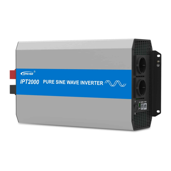
2 Appearance IPT350-xx IPT500-xx IPT1000-xx... - Page 12 IPT1500-XX IPT2000-XX IPT3000-XX...
- Page 13 IPT4000-XX IPT5000-42 The above products' appearance is only used as the terminal description. The DC input and AC output port vary with different models; please refer to the actual CAUTION product appearance for details. ③ ❶ ❻ RS485 communication port DC input terminal positive ❷...
- Page 14 ① Cooling fan Conditions to start the cooling fan: IPT1500-11 IPT1500-21 Heat sink temperature is higher than 45℃ or IPT1500-41 The internal inverter temperature is higher than 45℃ or IPT1500-12 The output power is higher than 700W IPT1500-22 IPT1500-42 IPT350-11 IPT350-21 IPT350-12...
- Page 15 Conditions to stop the cooling fan: IPT1000-11 Heat sink temperature is lower than 40℃ and IPT1000-21 The internal inverter temperature is lower than 40℃ and IPT1000-12 The output power is lower than 300W IPT1000-22 IPT1500-11 IPT1500-21 Heat sink temperature is lower than 40℃ and IPT1500-41 The internal inverter temperature is lower than 40℃...
- Page 16 ② The AC outlets vary with different products. Please refer to Chapter 3 Naming rule for the specific supported outlet types. ③ The RS485 communication port can be connected to the remote meter, Bluetooth module, WIFI module, PC, etc., for parameter setting and remote monitoring. ...
-
Page 17: Naming Rule
With reverse polarity and anti-surge current protection Explanations for the AC output port: Single terminal, single outlet or 2 pcs outlets for the AC output port Type Applicable product Number IPT series 1 pcs Terminal IPT350/500-x2 1 pcs C - Chinese dual-socket IPT1000/1500/2000-x2... - Page 18 IPT350/500-x2 1 pcs A - Australia IPT1000/1500/2000-x2 2 pcs IPT350/500-x2 1 pcs UK - United Kingdom IPT1000/1500/2000-x2 2 pcs IPT350/500-x2 1 pcs F - French IPT1000/1500/2000/3000-x2 2 pcs IPT350/500-x1 1 pcs IPT1000/1500-x1 2 pcs N - North American IPT2000-x1 2 pcs GFCI - Ground Fault Circuit IPT1000/1500/2000-x1...
- Page 19 TUK - Terminal + United Kingdom TE - Terminal + European Terminal*1 IPT4000/5000-42 Outlet*1 TF - Terminal + French IPT3000-x1 Terminal*1 TN - Terminal + America IPT4000-41 Outlet*1 GFCI outlets need to be tested after power-on to ensure proper operation. ...
-
Page 20: Connection Diagram
4 Connection diagram The DC input and AC outlets located on different sides The DC input and AC outlets are located on different sides, such as IPT350-xx, IPT500-xx, IPT1000-xx, IPT1500-xx, IPT2000-xx, and IPT3000-42. The following takes IPT2000-2x as an example to introduce the system connection. -
Page 21: Installation
5 Installation 5.1 Attentions Read all the installation instructions carefully in the manual before installation. Be very careful when installing the batteries. When installing the open-type lead-acid battery, please wear eye protection and rinse with clean water in time for battery acid contact. ... - Page 22 IPT500-21 6mm² /10AWG RNB5.5-6 DC/2P-32A IPT500-22 6mm² /10AWG RNB5.5-6 DC/2P-32A IPT1000-11 25mm /3AWG RNB38-6 DC/2P—125A IPT1000-12 25mm /3AWG RNB38-6 DC/2P—125A IPT1000-21 16mm /5AWG RNB14-6S DC/2P—63A IPT1000-22 16mm /5AWG RNB14-6S DC/2P—63A IPT1500-11 25mm /3AWG* 2 RNB60-6 DC-100A(2P in parallel) IPT1500-12 25mm /3AWG* 2 RNB60-6 DC-100A(2P in parallel)
-
Page 23: Mounting
IPT1000-11 2.5mm² /13AWG AC/2P—16A IPT1000-12 1.5mm /15AWG AC/2P—10A IPT1000-21 2.5mm² /13AWG AC/2P—16A IPT1000-22 1.5mm /15AWG AC/2P—10A IPT1500-11 /11AWG AC/2P—25A IPT1500-12 1.5mm /15AWG AC/2P—10A IPT1500-21 /11AWG AC/2P—25A IPT1500-22 1.5mm /15AWG AC/2P—10A IPT1500-41 /11AWG AC/2P—25A IPT1500-42 1.5mm /15AWG AC/2P—10A IPT2000-11 /11AWG AC/2P—32A IPT2000-12 2.5mm²... - Page 24 And a minimum clearance of 150mm from the upper and lower edges of the inverter is recommended to ensure natural thermal convection. The following takes IPT3000-1x as an example to introduce the wiring. Ventilation is highly recommended if mounted in an enclosure. CAUTION Step3: Wiring The AC loads shall be determined by the continuous output power of the inverter.
- Page 25 Battery Definition of the AC output port (it varies with different product models; please refer to the actual product.) The AC output ports of IPT3000-11 include AC terminal and North American standard outlets. The following takes the AC terminal as an example.) It is recommended to use a multi-stranded wire with a wire diameter of not more than 4mm ...
- Page 26 Turn off the inverter before removing the wiring. Then, insert a sharp tool into the small hole (on the top of the port) and pull out the wiring forcefully. Connect the AC load Optional accessories RS485 communication port RJ45 Pin Definition: Definition Instruction Definition...
- Page 27 Connect optional accessories Remote switch (RJ11) RJ11 port RJ11 Pin Definition: Definition Instruction Definition Instruction Switch+ Switch+ LED_R Red light drive Switch- Switch- Power GND +5VDC 5V/200mA LED_G Green light drive Connect remote switch...
- Page 28 Step 4:Power on the inverter ⑴ Connect the breaker at the inverter input terminal or the fuse at the battery terminal. ⑵ Turn on the inverter switch, and the green indicator will be lighted on, which states a normal AC output.
-
Page 29: Protections
6 Protections 1) Input voltage protection The following rules must be followed when modifying the battery's input voltage parameters: Over voltage limiting voltage (16.2/32.2/64.4V) ≥ Over voltage disconnect voltage ≥ Over voltage reconnect voltage +1V. Over voltage reconnect voltage ≥ Low voltage reconnect voltage. Low voltage reconnect voltage ≥... - Page 30 IPT1000-21 Buzzer beeps. IPT1000-22 Red indicator slowly flashes. IPT1500-11 IPT1500-12 IPT1500-21 IPT1500-22 IPT1500-41 IPT1500-42 IPT2000-11 The output is switched OFF S>2P (Input rated voltage) IPT2000-12 after 5 seconds. IPT2000-21 (S: Output power; P : Rated power) Buzzer beeps. IPT2000-22 Red indicator slowly flashes. IPT2000-41 IPT2000-42 IPT3000-21 ...
- Page 31 Red indicator slowly flashes. The output is switched OFF S>1.4P (Input rated voltage) after 5 seconds. (S: Output power; P : Rated power) Buzzer beeps. Red indicator slowly flashes. When the overload protection happens, the AC output cannot recover automatically. The AC output will be shut down according to the multiple of the overload.
-
Page 32: Troubleshooting
7 Troubleshooting A high voltage occurs inside the inverter. DO NOT try to repair or maintain the inverter by yourself, and it may cause an electric shock. WARNING Possible Faults Troubleshooting reasons Check whether the DC input voltage is Green indicator Slowly lower than10.8/21.6/43.2V The DC input... -
Page 33: Maintenance
8 Maintenance For good performance, the following inspections and maintenance tasks are recommended at least two times per year. Make sure no block on airflow around the inverter. Clear up any dirt and fragments on the heat sink. Check all the naked wires to ensure insulation is not damaged by sun exposure, frictional wear, dryness, insects or rats, etc. -
Page 34: Specifications
9 Specifications Instructions for the ① / ② / ③ marked in specifications table: ① Only the customized products with anti-surge function, the "Surge current when power on" is valid; other products, the actual surge current prevails. ② It means the rated output efficiency when the load power equals the continuous output power under the rated DC input voltage. ③... - Page 35 No-load current < 0.8A < 0.4A < 0.8A < 0.5A RS485 com. port 5VDC/200mA Mechanical parameters Input terminal Dimension(L x W x H) 229 × 160 × 73mm 286 × 160 × 73mm Mounting size 205 × 75mm 262 × 75mm Φ5mm Φ5mm Mounting hole size...
- Page 36 No-load current < 0.8A < 0.6A < 1.0A < 0.9A < 0.5A RS485 port 5VDC/200mA Mechanical parameters Input terminal Dimension (L x W x H) 371 × 228 × 118mm 387 × 228 × 118mm Mounting size 345 × 145mm 361 ×...
- Page 37 RS485 com. port 5VDC/200mA Mechanical parameters Input terminal Dimension (L x W x H) 420 × 228 × 118mm 421 × 228 × 118mm Mounting size 395 × 145mm 395 × 145mm Φ6mm Φ6mm Mounting hole size Net Weight 7.5kg 6.5kg Parameter IPT3000-11...
- Page 38 Mechanical parameters Input terminal Dimension (L x W x H) 550 × 270 × 143mm 521 × 270 × 143mm 516 x 228 x 118mm 521 × 270 × 143mm Mounting size 525 × 145mm 495 × 145mm 490 x 145mm 495 ×...
- Page 39 Input terminal Dimension (L x W x H) 229 × 160 × 73mm 286 × 160 × 73mm Mounting size 205 × 75mm 262 × 75mm Φ5mm Φ5mm Mounting hole size Net Weight 1.5kg 2.3kg Parameter IPT1000-12 IPT1000-22 IPT1500-12 IPT1500-22 IPT1500-42 Continuous output power 1000W@35℃@Rated input voltage...
- Page 40 Mounting size 345 × 145mm 361 × 145mm Φ6mm Φ6mm Mounting hole size Net Weight 4.8kg 5.8kg Parameter IPT2000-12 IPT2000-22 IPT2000-42 Continuous output power 2000W@35℃@Rated input voltage Surge power 4000W@5S Surge current when power < 100A < 100A < 50A ①...
- Page 41 Net Weight 7.8kg 6.5kg 6.5kg Parameter IPT3000-12 IPT3000-22 IPT3000-42 IPT4000-42 IPT5000-42 4000W@35℃@Rated 5000W@35℃@Rated Continuous output power 3000W@35℃@Rated input voltage input voltage input voltage Surge power 6000W@5S 8000W@5S Surge current when power < 100A < 100A < 65A < 65A ① Output voltage 220VAC (±3%);...
- Page 42 Environment parameters Working temperature -20℃ ~ +60℃ (Refer to the Derating Curve) -35 ℃ ~ +70 ℃ Storage temperature ≤ 95% (N.C.) Relative humidity Enclosure IP20 < 5000m (If the altitude exceeds 1000 meters, the rated power will be Altitude reduced according to IEC62040.)
-
Page 43: Appendix 1 Disclaimers
Appendix 1 Disclaimers The warranty does not apply to the following conditions: Damage caused by improper use or inappropriate environment. Load current/voltage/power exceeds the limit value of the inverter. Damage caused by working temperature exceeds the rated range. ... - Page 44 HUIZHOU EPEVER TECHNOLOGY CO., LTD. Beijing Tel: +86-10-82894896/82894112 Huizhou Tel: +86-752-3889706 E-mail: info@epever.com Website: www.epever.com...
Need help?
Do you have a question about the IPT Series and is the answer not in the manual?
Questions and answers