
Related Manuals for Epever Sunshine Solar IP350-Plus


Summary of Contents for Epever Sunshine Solar IP350-Plus
- Page 1 Pure sine wave inverter USER MANUAL Model IP350-Plus, IP500-Plus IP1000-Plus, IP1500-Plus IP2000-Plus, IP3000-Plus IP4000-Plus, IP5000-Plus...
-
Page 2: Table Of Contents
Contents Important safety instructions ..................1 1 Overview ........................4 2 Appearance ......................6 3 Naming rule ......................12 4 Connection diagram....................13 5 Remote meter.......................15 5.1 Appearance ......................... 15 5.2 Status display ........................15 5.3 Buttons ..........................16 5.4 LCD interface ........................16 5.5 Settings ..........................16 5.6 Error code.......................... -
Page 3: Important Safety Instructions
Important safety instructions Please reserve this manual for future review. This manual contains all safety, installation, and operation instructions for the IPower- Plus series high-frequency pure sine wave inverter ("inverter" referred to in this manual). 1. Explanation of symbols Please read related literature accompanying the following symbols to efficiently use the product and ensure personal and property safety. - Page 4 �� When installing the inverter, you must evaluate whether any arc danger exists in the operation area. �� The inverter needs to be connected to a battery. The battery's minimum capacity (Ah) is recommended to be five times the current equals the inverter's rated output power divided by the battery voltage.
- Page 5 8. Dangerous operations which would cause electric arc, fire or explosion �� Touch the wire end that hasn't been insulation treated and maybe electriferous. �� Touch the wiring copper row, terminals, or internal modules of the inverter that may be electriferous. ��...
-
Page 6: Overview
1 Overview IPower-Plus is a new generation of pure sine wave inverter compatible with the lithium battery system. This new inverter adopts surge current suppression technology to effectively prevent the surge current from damaging the lithium battery cells and BMS (Battery Management System). Also, adopting the voltage and current double closed-loop control algorithm brings the inverter a faster response and better resistance to the load impact. - Page 7 �� External switch contact design to allow remote control �� IEC62109, EN61000, RoHS approved ① Configure the parameters via the local LCD meter, remote LCD meter, phone Apps, and PC software. ② This function is unavailable for inverters with 48V input voltage. ③...
-
Page 8: Appearance
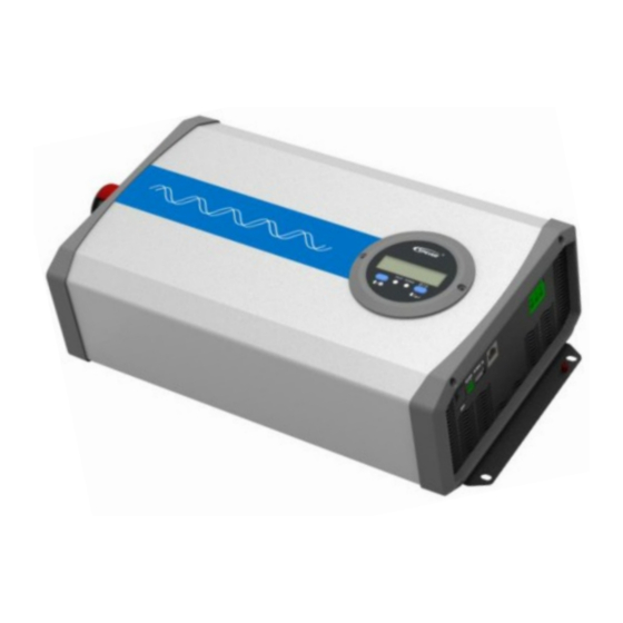
2 Appearance IP350-xx-Plus � �� Appearance with decorative cover is suitable for AC output of T-terminal / C-Chinese dual socket / N-North America �� Appearance without decorative cover is suitable for AC output of A-Australia / E-European / F-French / UK-United Kingdom IP500-xx-Plus �... - Page 9 �� Appearance without decorative cover is suitable for AC output of A-Australia / E-European / F-French / UK-United Kingdom IP1000-xx-Plus � IP1500-xx/IP2000-2x/IP2000-4x/IP3000-42-Plus �...
- Page 10 � IP2000-1x-Plus IP3000-1x-Plus � � IP3000-2x-Plus...
- Page 11 � IP3000-41/IP4000-4x/IP5000-4x-Plus ❶ ❻ DC input terminal positive RS485 communication port ❷ ❼ ③ DC input terminal negative USB output port 5VDC/Max.1A ❸ ❽ ① External switch port Cooling fan ❹ ❾ Inverter switch ❺ ❿ ② Grounding terminal AC outlet ①...
- Page 12 IP2000-11-Plus(T) IP2000-12-Plus(T) IP2000-21-Plus(T) IP2000-22-Plus(T) IP2000-41-Plus(T) IP2000-42-Plus(T) IP3000-11-Plus(T) IP3000-12-Plus(T) IP3000-21-Plus(T) IP3000-22-Plus(T) IP3000-41-Plus(T) IP3000-42-Plus(T) IP4000-41-Plus(T) IP4000-42-Plus(T) IP5000-42-Plus(T) Symbols of A/C/E/F/N/UK/T mean different AC outlets: A-Australia, C-Chinese dual-socket, E-European, F-French, N-North America, UK-United Kingdom, and T-Terminal. Conditions to stop the cooling fan: � IP1000-11-Plus(T/N) Heat sink temperature is lower than 40℃...
- Page 13 IP3000-11-Plus(T) IP3000-12-Plus(T) IP3000-21-Plus(T) IP3000-22-Plus(T) IP3000-41-Plus(T) IP3000-42-Plus(T) IP4000-41-Plus(T) IP4000-42-Plus(T) IP5000-42-Plus(T) IP350-11-Plus(T/N) IP350-12-Plus(T/C/A/E/F/UK) IP350-21-Plus(T/N) Heat sink temperature is lower than 40℃ and IP350-22-Plus(T/C/A/E/F/UK) The internal inverter temperature is lower than 40℃ and IP500-11-Plus(T/N) The output power is lower than 30% of the rated power IP500-12-Plus(T/C/A/E/F/UK) IP500-21-Plus(T/N) IP500-22-Plus(T/C/A/E/F/UK)
-
Page 14: Naming Rule
3 Naming rule... -
Page 15: Connection Diagram
4 Connection diagram �� IP350-xx-Plus (take the “Appearance with decorative cover” as an example) �� IP500-xx-Plus(take the “Appearance with decorative cover” as an example) �� IP1000-xx/IP1500-xx/IP2000-2x/IP2000-4x/IP3000-42-Plus... - Page 16 �� IP2000-1x-Plus �� IP3000-1x-Plus �� IP3000-2x/IP3000-41/IP4000-4x/IP5000-4x-Plus It is recommended to connect the inverter DC input terminal to the battery terminal directly. DO NOT connect it to the charge source terminal. Otherwise, the charging CAUTION voltage spikes of the charge source may cause over-voltage protection of the inverter.
-
Page 17: Remote Meter
5 Remote meter 5.1 Appearance ❶ ❹ Working status indicator(Blue) DOWN/Enter button ❷ ❺ UP/Setting button Output ON/OFF button ❸ ❻ Fault indicator(red) Fixing screws 5.2 Status display Working status indicator Fault indicator Buzzer Status Output voltage Blue ON solid Red OFF No beeps normal... -
Page 18: Buttons
5.3 Buttons Click Move up In the real-time interface, press it for 2s to enter the setting interface. Press for 2s In the setting interface, press it for 2s to enter the parameters configuration interface. Click Move down Press it to turn on/off the load output (default ON) in the Press for 2s real-time interface. -
Page 19: Error Code
Display Parameters Default User define 220VAC 220VAC/ 230Vac ① Output voltage class 110VAC 110VAC/ 120VAC Output frequency class 50Hz 50Hz/60Hz ① LCD backlight time 30s/ 60s/100s(ON solid) 12V: 10.8V 12V: 10.5V~14.2V; step size 0.1V Low voltage 24V: 21.6V 24V: 21V-30.2V; step size 0.1V ②... -
Page 20: Installation
6 Installation 6.1 Attentions Read all the installation instructions carefully in the manual before installation. � � Be very careful when installing the batteries. When installing the open-type lead-acid battery, please wear eye protection and rinse with clean water in time for battery acid contact. �... - Page 21 IP1000-11-Plus(T/N) 25mm /3AWG RNB38-6 DC/2P-125A IP1000-12-Plus(A/E/C/T) 25mm /3AWG RNB38-6 DC/2P-125A IP1000-21-Plus(T/N) 16mm /5AWG RNB14-6S DC/2P-63A IP1000-22-Plus(A/E/C/T) 16mm /5AWG RNB14-6S DC/2P-63A IP1500-11-Plus(T/N) 25mm /3AWG*2 RNB60-6 DC-100A(2P in parallel) IP1500-12-Plus(T) 25mm /3AWG*2 RNB60-6 DC-100A(2P in parallel) IP1500-21-Plus(T/N) 16mm /5AWG RNB14-6S DC/2P-125A IP1500-22-Plus(T) 16mm /5AWG RNB14-6S...
-
Page 22: Mounting
IP500-21-Plus(T/N) 1mm²/18AWG AC/2P—10A IP500-22-Plus(T/C/A/E/F/UK) 0.5mm²/20AWG AC/2P—10A IP1000-11-Plus(T/N) 2.5mm²/13AWG AC/2P-16A IP1000-12-Plus(A/E/C/T) 1.5mm /15AWG AC/2P-10A IP1000-21-Plus(T/N) 2.5mm²/13AWG AC/2P-16A IP1000-22-Plus(A/E/C/T) 1.5mm /15AWG AC/2P-10A IP1500-11-Plus(T/N) /11AWG AC/2P-25A IP1500-12-Plus(T) 1.5mm /15AWG AC/2P-10A IP1500-21-Plus(T/N) /11AWG AC/2P-25A IP1500-22-Plus(T) 1.5mm /15AWG AC/2P-10A IP1500-41-Plus(T/N) /11AWG AC/2P-25A IP1500-42-Plus(T) 1.5mm /15AWG AC/2P-10A IP2000-11-Plus(T) /11AWG... - Page 23 Step 2: Determine the installation location and heat-dissipation space To ensure natural thermal convection, you should install the inverter in a place with sufficient airflow and a minimum clearance of 150mm from the inverter's upper and lower edges. Ventilation is highly recommended if mounted in an enclosure. CAUTION ��...
- Page 24 �� IP3000-1x-Plus �� IP3000-2x/IP3000-41/IP4000-4x/IP5000-4x-Plus Step3: Wiring The AC loads shall be determined by the continuous output power of the inverter. The AC load's surge power must be lower than the instantaneous surge power of the WARNING inverter, or the inverter will be damaged. ��Set the inverter switch to OFF status before wiring.
- Page 25 ❷ Battery ❸ AC loads 1) Definition of the AC output terminal �� It is recommended to use a multi-stranded wire with a wire diameter of not more than 4mm �� Add solder to the connection point when selecting the multi-stranded wire and directly insert it into the corresponding port.
- Page 26 2) Connect the AC load ❹ Optional accessories 1) RS485 communication port RJ45 Pin Definition: Definition Definition 5VDC RS-485-A 5VDC RS-485-A RS-485-B RS-485-B 2) Connect optional accessories...
- Page 27 ❺ USB port (USB port is not available for inverters with 48V input voltage.) Step 4:Power on the inverter ⑴ Switch on the breaker at the inverter input terminal or the fuse at the battery end. ⑵ Turn on the inverter switch; the blue indicator will be lighted on, indicating a normal AC output. ⑶...
-
Page 28: Rotate The Lcd
6.4 Rotate the LCD ⑴ Remove the screws of the LCD unit with a screwdriver, and rotate it 180°. ⑵ Secure the screws of the LCD unit to the inverter. -
Page 29: Protections
7 Protections 1) Input reverse polarity protection When the DC input terminal's polarity is reversed, the indicator will not light up after power on. The buzzer will not sound, and the inverter will not work. The inverter will start to work normally after correcting the error wiring. - Page 30 IP500-11-Plus flashes. IP500-12-Plus LCD displays the IP500-21-Plus The output is switched OFF IP500-22-Plus after 30 seconds. IP1000-11-Plus S=1.5P Buzzer beeps. IP1000-12-Plus (S: Output power; P : Rated power) indicator slowly IP1000-21-Plus flashes. IP1000-22-Plus LCD displays the IP1500-11-Plus The output is switched OFF IP1500-12-Plus after 10 seconds.
- Page 31 The output is switched OFF after 5 seconds. S>1.7P (Rated input voltage) Buzzer beeps. (S: Output power; P : Rated power) The red indicator slowly flashes. LCD displays the The output is switched OFF after 1 minute. S=1.2P Buzzer beeps. (S: Output power;...
-
Page 32: Troubleshooting
8 Troubleshooting A high voltage will occur inside the inverter. DO NOT try to repair or maintain the inverter by yourself; it may cause an electric shock. WARNING Faults Reasons Troubleshooting Check whether the DC input voltage is Blue indicator The DC input lower than10.8/21.6/43.2V... -
Page 33: Maintenance
9 Maintenance The following inspections and maintenance tasks are recommended at least two times per year for the best performance. �� Make sure no block on airflow around the inverter. Clear up any dirt and fragments on the heat sink. ��... -
Page 34: Specifications
10 Specifications The tags ① / ② in the specification tables are explained as follows. ① It is measured in the condition of continuous output power and rated input voltage. ② It means the max. output efficiency when the inverter is connected with different loads under the rated input voltage. Parameters IP350-11-Plus IP350-21-Plus... - Page 35 Dimension (L×W×H) 229 × 160 × 73mm 286 × 163.5 × 78mm Mounting size 205 × 75mm 262 × 75mm Mounting hole size Φ5mm Φ5mm Net Weight 1.5Kg 2.3kg Parameters IP1000-11-Plus IP1000-21-Plus IP1500-11-Plus IP1500-21-Plus IP1500-41-Plus Continuous output power 1000W@35℃@ Rated input voltage 1500W@35℃@ Rated input voltage Surge power 2000W@5S...
- Page 36 Mounting size 345 × 145mm 361 × 145mm Mounting hole size Φ6mm Φ6mm Net Weight Parameters IP2000-11-Plus IP2000-21-Plus IP2000-41-Plus Continuous output power 2000W@35℃@ Rated input voltage Surge power 4000W@5S Surge current when power on < 100A < 100A < 50A Output voltage 110VAC (±3%);...
- Page 37 Net Weight 6.5kg 6.5kg Parameters IP3000-11-Plus IP3000-21-Plus IP3000-41-Plus IP4000-41-Plus 4000W@35℃@Rated Continuous output power 3000W@35℃@Rated input voltage input voltage Surge power 4800W@5S 6000W@5S 6000W@5S 8000W@5S Surge current when power on < 100A < 100A < 65A < 65A Output voltage 110VAC (±3%); 120VAC (-7%~+3%) Output frequency 50/60Hz ±...
- Page 38 Parameters IP350-12-Plus IP350-22-Plus IP500-12-Plus IP500-22-Plus Continuous output power 350W@35℃@ Rated input voltage 500W@35℃@ Rated input voltage Surge power 700W@5S 1000W@5S Surge current when power on < 30A < 50A Output voltage 220VAC (±3%); 230VAC (-7%~+3%) Output frequency 50/60Hz ± 0.2% Output wave Pure Sine Wave Output distortion THD...
- Page 39 Parameters IP1000-12-Plus IP1000-22-Plus IP1500-12-Plus IP1500-22-Plus IP1500-42-Plus Continuous output power 1000W@35℃@ Rated input voltage 1500W@35℃@ Rated input voltage Surge power 2000W@5S 3000W@5S Surge current when power on < 100A < 100A < 50A Output voltage 220VAC (±3%); 230VAC (-7%~+3%) Output frequency 50/60Hz ±...
- Page 40 Parameters IP2000-12-Plus IP2000-22-Plus IP2000-42-Plus Continuous output power 2000W@35℃@ Rated input voltage Surge power 4000W@5S Surge current when power on < 100A < 100A < 50A Output voltage 220VAC (±3%); 230VAC (-7%~+3%) Output frequency 50/60Hz ± 0.2% Output wave Pure Sine Wave Output distortion THD THD ≤...
- Page 41 Parameters IP3000-12-Plus IP3000-22-Plus IP3000-42-Plus IP4000-42-Plus IP5000-42-Plus 4000W@35℃@Rated 5000W@35℃@Rated Continuous output power 3000W@35℃@Rated input voltage input voltage input voltage Surge power 6000W@5S 8000W@5S 8000W@5S Surge current when power < 100A < 100A < 65A < 65A < 65A Output voltage 220VAC (±3%); 230VAC (-7%~+3%) Output frequency 50/60Hz ±...
- Page 42 Environment parameters Environment temperature -20℃ ~ +60℃ (Refer to the Derating Curve) Storage temperature -35℃ ~ +70℃ Relative humidity < 95% (N.C.) Enclosure IP20 Altitude < 5000m (If the altitude exceeds 1000 meters, the rated power will be reduced according to IEC62040.)
-
Page 43: Appendix 1 Disclaimers
Appendix 1 Disclaimers The warranty does not apply to the following conditions: �� Damage is caused by improper use or an inappropriate environment. �� Load current/voltage/power exceeds the limit value of the inverter. �� Damage caused by working temperature exceeds the rated range. ��... - Page 44 Registered office Sunshine Solar Limited Unit 30, Ashwellthorpe Industrial Estate Ashwellthorpe Norwich Norfolk NR16 1ER Company Registration: 5105890 - registered in England & Wales VAT Registration: GB 868 839 842 Telephone: +44 (0)1508 488188 Email: support@sunshinesolar.co.uk...
Need help?
Do you have a question about the Sunshine Solar IP350-Plus and is the answer not in the manual?
Questions and answers