
Related Manuals for Epever IPower-Plus Series


Summary of Contents for Epever IPower-Plus Series
- Page 1 Pure sine wave inverter USER MANUAL IP350-Plus, IP500-Plus IP1000-Plus, IP1500-Plus IP2000-Plus, IP3000-Plus IP4000-Plus, IP5000-Plus...
-
Page 3: Table Of Contents
Contents Important safety instructions 1 Overview 2 Appearance 3 Naming rule 4 Connection diagram 5 Remote meter 5.1 Appearance 5.2 Buttons 5.3 LCD interface 5.3.1 Real-time interface 5.3.2 Parameters setting 5.3.3 Power Saving Mode 5.3.4 Parameters user define 5.4 Error code 6 Installation 6.1 Attentions 6.2 Wire size and circuit breaker... -
Page 4: Important Safety Instructions
Important safety instructions Please reserve this manual for future review. This manual contains all safety, installation, and operation instructions for the IPower-Plus series high-frequency pure sine wave inverter ("inverter" referred to in this manual). 1. Explanation of symbols Please read related literature accompanying the following symbols to efficiently use the product and ensure personal and property safety. - Page 5 Operate and maintain the inverter. 4. Safety cautions before installation When you receive the inverter, check whether there is any damage in transportation. Contact the transportation company, our local distributor, or our IMPORTANT company for any problem. When placing or moving the inverter, follow the instructions in the manual. ...
- Page 6 inverter be less than 3 meters. If greater than 3 meters, please reduce the current density of the connection wire. A fuse or breaker should be used between battery and Inverter; the fuse or breaker's rated current should be twice the inverter rated input current. ...
- Page 7 Once an accident occurs, it must be handled by professional and technical personnel. Improper operations would cause more serious accidents. WARNING 9. Safety cautions for stopping the inverter After the inverter stop running for five minutes, the internal conductive modules could be touched. ...
-
Page 8: Overview
1 Overview IPower-Plus is a new generation of pure sine wave inverter compatible with the lithium battery system. This new inverter adopts surge current suppression technology to effectively prevent the surge current from damaging the lithium battery cells and BMS (Battery Management System). Also, adopting the voltage and current double closed-loop control algorithm brings the inverter a faster response and better resistance to the load impact. - Page 9 ④ Support a variety of options by connecting with the RS485 com. port External switch contact design to allow remote control EN/IEC62109, EN61000-6-1/3, RoHS, ETL and FCC approved ① There is no LCD meter for the IP350-Plus series. ②...
-
Page 10: Appearance
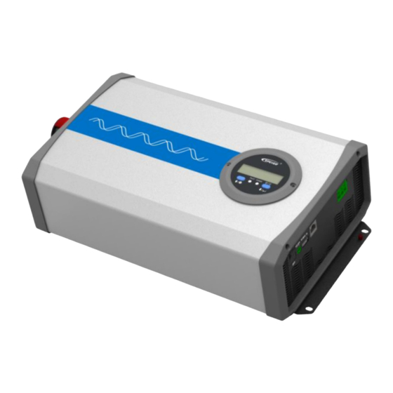
2 Appearance IP350-xx-Plus Appearance with decorative cover is suitable for AC output of T-terminal / C-Chinese dual socket / N-North America Appearance without decorative cover is suitable for AC output of A-Australia / E-European / F-French / UK-United Kingdom ... - Page 11 Appearance without decorative cover is suitable for AC output of A-Australia / E-European / F-French / UK-United Kingdom IP1000-xx-Plus IP1500-xx/IP2000-2x/IP2000-4x/IP3000-42-Plus...
- Page 12 IP2000-1x-Plus IP3000-1x-Plus IP3000-2x-Plus...
- Page 13 IP3000-41/IP4000-4x/IP5000-4x-Plus ❶ ❻ DC input terminal positive RS485 communication port ❷ ❼ ③ DC input terminal negative USB output port 5VDC/Max.1A ❸ ❽ ① External switch port Cooling fan ❹ ❾ Inverter switch ❺ ❿ ② Grounding terminal AC output port ①...
-
Page 14: Naming Rule
3 Naming rule Explanations for the AC output port: Suffix Instruction Figure Suffix Instruction Figure Terminal Chinese Terminal + Chinese dual-socket Terminal + European socket European Australia Terminal + Australia socket United Terminal + United Kingdom Kingdom socket French Terminal + French socket American Terminal +... - Page 15 American Terminal + socket American(Applicable (Applicable to to 2000W and above 2000W and products) above products) American socket GFCI TGFCI Terminal + American (Ground Fault Circuit Interrupt) GFCI outlets need to be tested after power-on to ensure proper operation. ...
-
Page 16: Connection Diagram
4 Connection diagram IP350-xx-Plus (take the “Appearance with decorative cover” as an example) IP500-xx-Plus(take the “Appearance with decorative cover” as an example) IP1000-xx/IP1500-xx/IP2000-2x/IP2000-4x/IP3000-42-Plus... - Page 17 IP2000-1x-Plus IP3000-1x-Plus IP3000-2x/IP3000-41/IP4000-4x/IP5000-4x-Plus It is recommended to connect the inverter DC input terminal to the battery terminal directly. DO NOT connect it to the charge source terminal. Otherwise, the charging CAUTION voltage spikes of the charge source may cause over-voltage protection of the inverter.
-
Page 18: Remote Meter
5 Remote meter 5.1 Appearance ❶ ❹ LCD Power indicator(Blue) DOWN/Enter button ❷ ❺ UP/Setting button Output ON/OFF button ❸ ❻ Fault indicator(red) Fixing screws The LCD display can be viewed clearly when the angle between the end-user's horizontal sight and the LCD screen is within 90°... -
Page 19: Lcd Interface
The long buzzer beeps for the parameter confirming and short beeps for other button operations. CAUTION 5.3 LCD interface 5.3.1 Real-time interface Click to browse the real-time interface. Battery voltage Load voltage Load current Load frequency Load power 5.3.2 Parameters setting Operation: Step1: In the real-time interface, press for 2s to enter the parameter setting interface. - Page 20 minimum power step is 1VA). When the actual load power is lower than the PSI (the power to enter the power saving mode), the system will automatically switch to the power saving mode, and then the device output is turned on for 1s and turned off for 5s.
-
Page 21: Parameters User Define
Step1: In the parameters setting interface, click the button to select the PSI parameter. Step2: Press and hold the button until the PSI value flashes. Step3: Click the button to set the PSI parameter. Click the button to decrease the PSI value by 1. ... -
Page 22: Error Code
12V: 12.5V 12V: 11.5V~15.2V; step size 0.1V Low voltage reconnect 24V: 25V 24V: 22V-31.2V; step size 0.1V ③ voltage 48V: 50V 48V: 43V-63.4V; step size 0.1V 12V: 14.5V 12V: 11.5V~15.2V; step size 0.1V Over voltage 24V: 29V 24V: 22V-31.2V; step size 0.1V ③... -
Page 23: Installation
6 Installation 6.1 Attentions Read all the installation instructions carefully in the manual before installation. Be very careful when installing the batteries. When installing the open-type lead-acid battery, please wear eye protection and rinse with clean water in time for battery acid contact. ... - Page 24 IP1000-11-Plus 25mm /3AWG RNB38-6 DC/2P-125A IP1000-12-Plus 25mm /3AWG RNB38-6 DC/2P-125A IP1000-21-Plus 16mm /5AWG RNB14-6S DC/2P-63A IP1000-22-Plus 16mm /5AWG RNB14-6S DC/2P-63A IP1500-11-Plus 25mm /3AWG RNB60-6 DC-100A(2P in parallel) IP1500-12-Plus 25mm /3AWG RNB60-6 DC-100A(2P in parallel) IP1500-21-Plus 16mm /5AWG RNB14-6S DC/2P-125A IP1500-22-Plus 16mm /5AWG RNB14-6S...
- Page 25 IP350-21-Plus 1mm² /18AWG AC/2P—6A IP350-22-Plus 1mm² /18AWG AC/2P—6A IP500-11-Plus 1mm² /18AWG AC/2P—10A IP500-12-Plus 1mm² /18AWG AC/2P—6A IP500-21-Plus 1mm² /18AWG AC/2P—10A IP500-22-Plus 1mm² /18AWG AC/2P—6A IP1000-11-Plus 2.5mm² /13AWG AC/2P-16A IP1000-12-Plus 1.5mm /15AWG AC/2P-10A IP1000-21-Plus 2.5mm² /13AWG AC/2P-16A IP1000-22-Plus 1.5mm /15AWG AC/2P-10A IP1500-11-Plus /11AWG AC/2P-25A...
-
Page 26: Mounting
6.3 Mounting Installation procedures: Step1: Professional personnel reads this manual carefully. Step 2: Determine the installation location and heat-dissipation space To ensure natural thermal convection, you should install the inverter in a place with sufficient airflow and a minimum clearance of 150mm from the inverter's upper and lower edges. It is not recommended to install the product in an enclosed cabinet, where the device cooling will be influenced. - Page 27 IP2000-1x-Plus IP3000-1x-Plus IP3000-2x/IP3000-41/IP4000-4x/IP5000-4x-Plus Step3: Wiring Turn off the inverter switch before wiring. Please do not connect the circuit breaker or fuse during the wiring and ensure that the poles' leads are connected correctly. CAUTION The terminals and ports on the side vary from the product models. Wiring sequence (The following wiring sequence is illustrated in the appearance "IP2000-2x-Plus", wiring positions of other inverters.
- Page 28 2. Battery connection A fuse must be installed on the battery side, conformed to the following requirements. 1. Fuse voltage is 1.5 to 2 times the inverter's rated voltage. 2. Fuse current is 2 to 2.5 times the inverter's rated current. CAUTION 3.
- Page 29 It is recommended to use a multi-stranded wire with a wire diameter of not more than 6mm Add solder to the connection point when selecting the multi-stranded wire and directly insert it into the corresponding port. Stop the inverter before removing the wiring. Then, insert a sharp tool into the small hole (on the top of the port) and pull out the wiring forcefully.
- Page 30 RJ45 Pin Definition: Definition Instruction Definition Instruction +5VDC RS485-A 5V/200mA RS485-A +5VDC RS485-A RS485-B RS485-B Power GND RS485-B 2) Connect optional accessories 5. USB port connection (USB port is not available for inverters with 48V input voltage.) Step 4:Power on the inverter ⑴...
-
Page 31: Rotate The Lcd
⑵ Turn on the inverter switch; the power indicator will be lighted on, indicating a normal AC output. ⑶ Turn on the AC loads one by one and check the inverter's running status and the loads. When supplying power for different loads, turning on the load with a large impulse current is recommended. -
Page 32: Protections
7 Protections 1) Input reverse polarity protection When the DC input terminal's polarity is reversed, the indicator will not light up after power on. The buzzer will not sound, and the inverter will not work. The inverter will start to work normally after correcting the error wiring. - Page 33 3) Overload protection IP350-11-Plus The output is switched OFF after 1 IP350-12-Plus minute. IP350-21-Plus S=1.2P Buzzer beeps. IP350-22-Plus (S: Output power; P : Rated power) The red indicator slowly flashes. IP500-11-Plus LCD displays the IP500-12-Plus IP500-21-Plus IP500-22-Plus IP1000-11-Plus The output is switched OFF after 30 IP1000-12-Plus seconds.
- Page 34 The output is switched OFF after 10 seconds. S=1.5P Buzzer beeps. (S: Output power; P : Rated power) The red indicator slowly flashes. LCD displays the IP3000-11-Plus The output is switched OFF after 5 seconds. S≥1.6P Buzzer beeps. (S: Output power; P : Rated power) The red indicator slowly flashes.
- Page 35 When the overload protection happens, the AC output cannot recover automatically. The AC output is shut down according to the multiple of the overload. Recover the CAUTION AC output after clearing the overload faults and restarting the inverter. 4) Output short circuit protection Faults Instruction The output is switched OFF...
-
Page 36: Troubleshooting
8 Troubleshooting A high voltage will occur inside the inverter. DO NOT try to repair or maintain the inverter by yourself; it may cause an electric shock. WARNING Faults Reasons Troubleshooting Check whether the DC input voltage is Blue indicator The DC input lower than10.8/21.6/43.2V... -
Page 37: Maintenance
9 Maintenance The following inspections and maintenance tasks are recommended at least two times per year for good performance. Make sure no block on airflow around the inverter. Clear up any dirt and fragments on the heat sink. Check all the naked wires to ensure insulation is not damaged by sun exposure, frictional wear, dryness, insects or rats, etc. -
Page 38: Specifications
10 Specifications 100/110/120VAC output Parameters IP350-11-Plus IP350-21-Plus IP500-11-Plus IP500-21-Plus Continuous output power 350W@35℃@ Rated input voltage 500W@35℃@35℃@ Rated input voltage Surge power 700W@5S 1000W@5S Surge current when power on < 30A < 50A Output voltage 100VAC/110VAC (± 3%); 120VAC (-7%~+3%) Output frequency 50/60Hz ±... - Page 39 Mounting size 205 × 75mm 262 × 75mm Φ5mm Φ5mm Mounting hole size Net Weight 1.5Kg 2.3kg ① It is measured in the condition of continuous output power and rated input voltage. ② It means the max. output efficiency when the inverter is connected with different loads under the rated input voltage. Parameters IP1000-11-Plus IP1000-21-Plus...
- Page 40 Dimension 371 × 231.5 × 123mm 387 × 231.5 × 123mm Mounting size 345 × 145mm 361 × 145mm Φ6mm Φ6mm Mounting hole size Net Weight 5.0kg 6.0kg ① It is measured in the condition of continuous output power and rated input voltage. ②...
- Page 41 Dimension 420 × 231.5 × 123mm 421 × 231.5 × 123mm 421 × 231.5 × 123mm Mounting size 395 × 145mm 395 × 145mm 395 × 145mm Φ6mm Φ6mm Φ6mm Mounting hole size Net Weight 8.0kg 6.5kg 6.5kg ① It is measured in the condition of continuous output power and rated input voltage. ②...
- Page 42 Input terminal Dimension 550 × 274 × 148mm 521 × 274 × 148mm 516 x 231.5 x 123mm 521 × 274 × 148mm Mounting size 525 × 145mm 495 × 145mm 490 x 145mm 495 × 145mm Φ6mm Φ6mm Φ6mm Φ6mm Mounting hole size Net Weight...
- Page 43 RS485 com. port 5VDC/200mA Mechanical parameters Input terminal 229 × 163.5 × 75mm (with decorative cover) 286 × 163.5 × 78mm (with decorative cover) Dimension 229 × 160 × 73mm (without decorative cover) 286 × 160 × 78mm (without decorative cover) Mounting size 205 ×...
- Page 44 USB output 5VDC/Max.1A 5VDC/Max.1A RS485 com. port 5VDC/200mA Mechanical parameters Input terminal Dimension 371 × 231.5 × 123mm 387 × 231.5 × 123mm Mounting size 345 × 145mm 361 × 145mm Φ6mm Φ6mm Mounting hole size Net Weight 5.0kg 6.0kg ①...
- Page 45 USB output 5VDC/Max.1A 5VDC/ Max.1A RS485 com. port 5VDC/ 200mA Mechanical parameters Input terminal Dimension 420 × 231.5 × 123mm 421 × 231.5 × 123mm 421 × 231.5 × 123mm Mounting size 395 × 145mm 395 × 145mm 395 × 145mm Φ6mm Φ6mm Φ6mm...
- Page 46 (30% loads) (30% loads) (30% loads) (30% loads) (30% loads) Idle current < 0.2A < 0.15A < 0.1A < 0.1A < 0.1A No-load current < 1.6A < 1.0A < 0.5A < 0.6A < 0.8A USB output 5VDC/Max.1A 5VDC/Max.1A RS485 com. port 5VDC/ 200mA Mechanical parameters Input terminal...
-
Page 47: Appendix 1 Disclaimers
Appendix 1 Disclaimers The warranty does not apply to the following conditions: Damage is caused by improper use or an inappropriate environment (humid, salt spray, corrosion, greasy, flammable, explosive, dust accumulative, or other severe environments). The actual current/voltage/power exceeds the limit value of the inverter. ... - Page 48 HUIZHOU EPEVER TECHNOLOGY CO., LTD. Tel: +86-752-3889706 E-mail: info@epever.com Website: www.epever.com...
Need help?
Do you have a question about the IPower-Plus Series and is the answer not in the manual?
Questions and answers