Epever IP1500-Plus Series User Manual
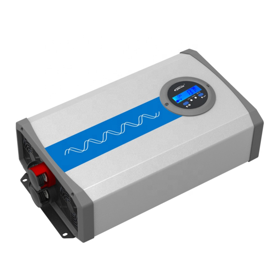
Pure sine wave inverter
Hide thumbs
Also See for IP1500-Plus Series:
- User manual (52 pages) ,
- User manual (44 pages) ,
- User manual (48 pages)
Table of Contents
Advertisement
Advertisement
Table of Contents

Related Manuals for Epever IP1500-Plus Series


Summary of Contents for Epever IP1500-Plus Series
- Page 1 PURE SINE WAVE INVERTER USER MANUAL Models: IP1500-Plus IP2000-Plus IP3000-Plus...
-
Page 3: Table Of Contents
Contents Important Safety Instructions ............1 1. Overview ................6 2. Characteristics ............... 8 3. Designations of models ............10 4. Schematic diagram for connections ........11 5. LCDdisplay unit ..............12 5.1 LCD ................12 5.2 LED indicator and buzzer ..........12 5.3 Button ................ -
Page 4: Important Safety Instructions
Important Safety Instructions Please reserve this manual for future review. This manual contains all the instructions about safety, installation, and operation for the IPower Plus series pure sine wave inverter (Shown as “inverter” in the rest of the manual). Symbols Definition To ensure safety and use the product efficiently, when you seethe below symbols in the manual, please pay attention to them and read the related content carefully. - Page 5 Familiar with related safety specification of the electrical system; Read through the whole manual and be familiar with operating procedures and safety precautions. 3. Technicians operating permission Install the inverter to the specified location; Pretesting the inverter; ...
- Page 6 WARNING: Make sure the inverter is clean and no electrical connection before installation. WARNING: Make sure there is enough heat dissipation space for the inverter installation, and do not install the inverter in humid, greasy, flammable, explosive, dust accumulative or other severe environments.
- Page 7 7.Safety cautions for inverter operation WARNING HOT SURFACE: Do NOT touch the inverter when it’s operating, the inverter case of the inverter will generate a high value of heat, also keep distance to the material or equipment affected by high temperature.
- Page 8 WARNING:Do NOT touch or open the external case before the device is shut off completely for ten minutes. 10. Safety cautions for inverter maintenance Testing equipment recommend to check the inverter without voltage or current; During installation and maintenance, please post temporary warning signs or put up roadblocks to prevent unrelated people from entering the area.
-
Page 9: Overview
1. Overview IPower Plus is a new series of pure sine wave inverter which compatible with the lithium battery system. This new inverter with the input surge current suppression technology, which effectively prevents the damage of surge current to lithium battery cell and BMS (Battery Management System). Also, the smart voltage and current double closed-loop control algorism bring the inverter a faster response and better resistance to load impact. - Page 10 High conversion efficiency. Extensive protection: input reverse polarity, input overvoltage, input low voltage, output overload, and short circuit, overheating. Air cooling control by dual condition (Temperature and Load) 180 degree rotatable LCD design to simplify the system wiring ...
-
Page 11: Characteristics
2. Characteristics IP1500-12-Plus/IP2000-**-Plus IP3000-12-Plus ❶ ❻ DC input terminal positive RS485 communication port ❷ ❼ ② DC input terminal negative USB output port 5VDC/Max.1A ❸ ❽ ① External switch connection point Ventilation fan ❹ ❾ Inverter switch ❺ ❿ AC output terminal Grounding terminal ①... - Page 12 2) The cooling fan will automatically turn off when the inverter reaches all the conditions as below. Heat sink temperature is lower than40℃. The Internal temperature is lower than 40℃. The output power is lower than 40% of the rated power. ②The products of the 48V input system do not support the USB output port.
-
Page 13: Designations Of Models
3. Designations of models... -
Page 14: Schematic Diagram For Connections
4. Schematic diagram for connections IP1500-12-Plus/IP2000-**-Plus IP3000-12-Plus CAUTION:Suggest that the DC input terminal of the inverter directly connects to the battery. DO NOT connect to the battery terminal of the charge source. Otherwise, the charging voltage spikes of the charge source may lead to over-voltage protection of the inverter. -
Page 15: Lcddisplay Unit
5. LCDdisplay unit 5.1LCD ❶ ❹ Working status indicator(Blue) DOWN/Enter button ❷ ❺ UP/Setting button Output ON/OFF button ❸ ❻ Fault indicator(red) Screw of the LCD 5.2 LED indicator and buzzer Working status Fault Buzzer Status indicator indicator Blue Buzzer Red off Output is normal on solid... -
Page 16: Button
flashing(1/4Hz) sounds Buzzer The output voltage Blue off Red off sounds is abnormal 5.3Button Press the button Enter the setting interface at the Press the button real-time interface and hold on 2s Enter the parameter’s setting interface at the setting interface Press the button Down Press the button... -
Page 17: Fault Code
Step 1:Long press to into the setting interface; Step2:Press to select the setting item; Step3:Long press and the digit is flashing to set the parameter; Step4:Long press to enter the parameter; Step5:Press to exit the setting interface. Display Parameter Default Setting range 220Vac 220Vac/230Vac... -
Page 18: Installation Instructions
6. Installation instructions 6.1General installation notes Please read the manual carefully to get familiar with the installation steps before installation. Be very careful when installing the batteries, especially flooded lead-acid batteries. Please wear eye protection, and have fresh water available to rinse if any contact with battery acid. -
Page 19: Wire Size &Breaker
6.2Wire size &breaker Wiring and installation should comply with national and local electrical requirements. Wire, terminals and breaker selection for battery Battery wire Ring Models Breaker size Terminal DC—100A IP1500-12-Plus(T) 35mm /1AWG RNB38-6 (2P in parallel) DC—125A IP2000-12-Plus(T) 50mm /1/0AWG RNB60-10 (2P in parallel) - Page 20 IMPORTANT: The inverter shall be installed in a place with sufficient airflow through the dissipation pad of the inverter and a minimum clearance of 150mm from the upper and lower edges of the inverter to ensure natural thermal convection. CAUTION: The inverter shall be cooling through case if installed in a closed box.
- Page 21 CAUTION: A fuse which current is 2 to 2.5 times the rated current of the inverter, it must be installed on the battery side with a distance from the battery not greater than 150mm. Wiring order: ❶Ground IP1500-12/IP2000-**-Plus IP3000-12-Plus ❷Battery IP1500-12/IP2000-**-Plus IP3000-12-Plus ❸...
- Page 22 Use multi-cores wire with no large than 4mm is recommended Tin soldering to connection point when using multi-cores wires and directly insert into the related hole. Cut off the power and use a sharp tool to insert it into the small hole (on the top of the wire) before removing the wire.
- Page 23 Connect accessories IP1500-12/IP2000-**-Plus IP3000-12-Plus ❺USB port IP1500-12/IP2000-**-Plus IP3000-12-Plus Step4:Power on the inverter ⑴ Switch on the input breaker or the fuse between inverter and battery. ⑵ Turn on the power switch to start the inverter, blue indicator on solid, and the AC output is normal. ⑶...
-
Page 24: Rotate The Lcd
turn on the loads with higher startup current first, such as television, then at last the loads work stably, turn on the loads with lower startup current, such as an incandescent lamp. ⑷ If the fault indicator is red and the buzzer alarms when turn on the inverter, please switch off the loads and inverter immediately. -
Page 25: Protection
7. Protection Input reverse polarity protection The electronic circuit works to protect the inverter from damage during input reverse polarity. After correcting the connection, the inverter will work properly. 2) Input overvoltage protection Input overvoltage protection (“Ui” is DC input voltage) Models Protection Default User-defined... - Page 26 LCD display The output is OFF Ui≤10.5V — — IP***-1*-Plus immediately The blue indicator Ui≤21.0V — — IP***-2*-Plus slowly flashing Buzzer sounds Ui≤42.0V — — IP***-4*-Plus LCD display Low voltage recover protection (“Ui” is DC input voltage) Models Recover Default User-defined Phenomenon...
- Page 27 Red indicator fast flashing recover automatically after 3 times attempt until restarting the inverter. display 6)Overtemperature Protection Phenomenon Instruction The heat sink or internal temperature is higher display Inverter turns OFF than some value. The heat sink or internal temperature is lower Inverter turns ON than some value.
-
Page 28: Troubleshooting
8. Troubleshooting WARNING DO NOT try to repair or maintain the inverter by own, and it may cause danger. Phenomenon Possible reasons Troubleshooting Measure the DC input voltage Blue indicator voltage lower slowly flashing DC input voltage than10.8/21.6/43.2V. Adjust Buzzer sounds under voltage the input voltage to recover display... -
Page 29: Maintenance
9. Maintenance The following inspections and maintenance tasks are recommended at least two times per year for the best performance. Make sure no block on airflow around the inverter. Clear up any dirt and fragments on the radiator. Check all the naked wires to make sure insulation does not damage for serious solarization—frictional wear, dryness, insects or rats, etc. -
Page 30: Technical Specifications
10.Technical Specifications Item IP1500-12-Plus(T) Output continuous power 1500W@35℃@ Rated input voltage Surge power 3000W@5S Output voltage 220VAC(± 3%);230VAC(-7%~+3%) Output frequency 50/60Hz± 0.2% Output wave Pure Sine Wave THD≤3%(Resistive load) Output distortion THD 0.2~1(VA≤Continuous output power) Load power factor Rated input voltage 12VDC Input voltage range 10.8~16VDC... - Page 31 Item IP2000-12-Plus(T) IP2000-22-Plus(T) IP2000-42-Plus(T) Output continuous power 2000W@35℃@ Rated input voltage Surge power 4000W@5S Output voltage 220VAC(± 3%);230VAC(-7%~+3%) Output frequency 50/60Hz± 0.2% Output wave Pure Sine Wave THD≤3%(Resistive load) Output distortion THD 0.2~1(VA ≤ Continuous output power) Load power factor Rated input voltage 12VDC 24VDC...
- Page 32 Item IP3000-12-Plus(T) Output continuous 3000W@35℃@ Rated input voltage power Surge power 6000W@5S Output voltage 220VAC(± 3%);230VAC(-7%~+3%) Output frequency 50/60Hz± 0.2% Output wave Pure Sine Wave Output distortion THD THD≤3%(Resistive load) 0.2~1(VA ≤ Continuous output power) Load power factor Rated input voltage 12VDC Input voltage range 10.8~16VDC...
- Page 33 Environmental parameters -20℃~+50℃ Working Temperature (Refer to the Reduced capacity curve) -35℃~ +70℃ Storage Temperature ≤ Humidity 95%(N.C.) IP20 Enclosure <5000m Altitude (Derating to operate according to IEC62040 at a height exceeding 1000m)
-
Page 34: Annexⅰdisclaimer
AnnexⅠDisclaimer The warranty does not apply under the following conditions: Damage caused by improper use or useofan inappropriate environment. Battery voltage exceeds the input voltage limit of the inverter. Damage caused by the working environment temperature exceeds the rated range. - Page 36 HUIZHOU EPEVER TECHNOLOGY CO., LTD. Beijing Tel: +86-10-82894896/82894112 Huizhou Tel: +86-752-3889706 E-mail: info@epsolarpv.com Website: www.epsolarpv.com www.epever.com...
Need help?
Do you have a question about the IP1500-Plus Series and is the answer not in the manual?
Questions and answers