Sign In
Upload
Manuals
Brands
ADLINK Technology Manuals
Desktop
SP-AL
ADLINK Technology SP-AL Manuals
Manuals and User Guides for ADLINK Technology SP-AL. We have
1
ADLINK Technology SP-AL manual available for free PDF download: User Manual
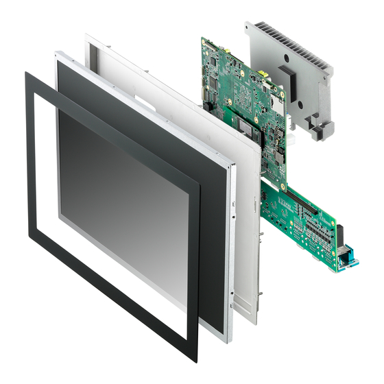
ADLINK Technology SP-AL User Manual (111 pages)
Open Frame Panel PC
Brand:
ADLINK Technology
| Category:
Desktop
| Size: 4 MB
Table of Contents
Table of Contents
7
List of Tables
13
List of Figures
15
Introduction
17
Features
17
General Specifications
18
Display/Touch Specifications
20
Power Consumption
21
Thermal Specification
22
Heat Sink Specifications
22
Routing Considerations
22
Mechanical Drawings
23
Panel
23
Figure 1-1: 10.1" Panel Front View
23
Figure 1-2: 10.1" Panel (Left) Side View
24
Panel
25
Figure 1-3: 12.1" Panel Front View
25
Figure 1-4: 12.1" Panel (Left) Side View
26
Panel
27
Figure 1-5: 15.6" Panel Front View
27
Figure 1-6: 15.6" Panel (Left) Side View
28
Panel
29
Figure 1-7: 18.5" Panel Front View
29
Figure 1-8: 18.5" Panel (Left) Side View
30
Panel
31
Figure 1-9: 21.5" Panel Front View
31
Figure 1-10: 21.5" Panel (Left) Side View
32
External I/O Connectors
33
DB-9P COM Port Connector
33
Table 1-1: External I/O Legend
33
Figure 1-11: External I/O
33
Table 1-2: DB-9P COM Port Pin Assignment
34
Figure 1-12: DB-9P COM Port
34
USB Ports
35
Displayport Connector
35
Table 1-3: USB Ports Pin Assignment
35
Figure 1-13: USB Ports
35
Table 1-4: Displayport Pin Assignment
36
Dual Gigabit Ethernet Ports
37
Table 1-5: Gigabit Ethernet Port LED Function
37
Internal I/O Connectors
38
Figure 1-14: Internal I/O (Mainboard Top Side)
38
Figure 1-15: Internal I/O (Mainboard Underside)
39
Power Connector
40
SMBUS Connector
40
Table 1-6: Internal I/O Legend
40
Table 1-7: Power Connector Pin Assignments
40
Figure 1-16: Power Connector
40
Mini Pcie Port
41
CMOS Jumper
41
Table 1-8: SMBUS Connector Pin Assignments
41
Figure 1-17: SMBUS Connector
41
USB 2.0 Port
42
Table 1-9: CMOS Jumper Pin Assignments
42
Figure 1-18: CMOS Jumper
42
Figure 1-19: USB 2.0 Port
42
I2C Connector
43
Table 1-10: USB 2.0 Port Pin Assignments
43
Table 1-11: I2C Connector Pin Assignments
43
Figure 1-20: I2C Connector
43
Data Input Keys
44
Figure 1-21: Data Input Connector
44
Power & Reset Connector
45
Table 1-12: Data Input Connector Pin Assignments
45
Speaker Connectors
46
Table 1-13: Power & Reset Connector Pin Assignments
46
Figure 1-22: Power & Reset Connector
46
Figure 1-23: 2W Speaker Connector
46
MIC In\Line out Connectors
47
SSD Slot
47
Table 1-14: 2W Speaker Connector Pin Assignments
47
Table 1-15: MIC In/Line out Pin Assignments
47
Figure 1-24: MIC In/Line out Connector
47
LED Connector
48
Table 1-16: LED Indicators
48
Figure 1-25: M.2 SSD Slot
48
Figure 1-26: LED Connector
48
I2C Connector
49
Table 1-17: LED Connector Pin Assignments
49
Figure 1-27: I2C Connector
49
Control Keys Connector
50
Table 1-18: I2C Connector Pin Assignments
50
Figure 1-28: Control Keys Connector
50
Debug Connector
51
Table 1-19: Control Keys Connector Pin Assignments
51
Table 1-20: Debug Connector Pin Assignments
51
Figure 1-29: Debug Connector
51
GPI/O Connector
53
Table 1-21: GPI/O Connector Pin Assignments
53
Figure 1-30: GPI/O Connector
53
SIM Card Slot
55
Sema
55
Figure 1-31: SIM Slot
55
Getting Started
57
Unpacking Checklist
57
External I/O Options
57
Installing/Changing 2.5" SATA SSD/HDD
59
Installing/Changing SO-DIMM
60
E3930 CPU-Equipped Models
60
E3950 CPU-Equipped Models
60
Installing/Changing a Mini Pcie Wireless Card
62
E3930 CPU-Equipped Models
62
E3950 CPU-Equipped Models
63
Connecting DC Power
64
Driver & Application Installation
65
Installing the Chipset Driver
65
Installing the Graphics Driver
66
Installing the Ethernet Driver
66
Installing the USB 3.0 Driver
67
Installing the I/O Driver
67
Installing the SEMA Utility, WDT and DI/O Drivers
67
A Appendix: BIOS Setup
69
Main
70
BIOS Information
70
System Information
70
System Time/System Date
71
Access Level
71
Board Information
72
Runtime Statistics
72
Advanced
73
CPU Configuration
74
Eist
74
Turbo Mode
74
Intel Virtualization Technology
74
C-States
74
Dts
75
Graphics Configuration
76
Data Formation and Color Depth
76
LVDS Output Mode
76
Polarity
76
Vsync Polarity
76
Hsync Polarity
77
Active LFP Config
77
LEP Panel Type
77
Power Management
79
Enable ACPI Auto Configuration
79
Enable Hibernation
79
ACPI Sleep State
79
Lock Legacy Resources
79
Mpcie Slot Wake
80
LAN Wake
80
RTC Wake System from S5
80
Emulation AT/ATX
80
LAN#1 Control
80
LAN#2 Control
80
Power Consumption
80
System Management
82
SEMA Features
82
Flags
82
Thermal Management
83
Critical Trip Point
83
Passive Cooling Trip Point
83
Watchdog Timer
84
Power-Up Watchdog
84
Runtime Watchdog
84
Super IO Configuration
85
Serial Console Redirection
86
Network Stack Configuration
87
Trusted Computing
88
USB Configuration
89
XHCI Hand-Off
89
USB Mass Storage Driver Support
89
USB Transfer Time-Out
89
Device Reset Time-Out
89
Device Power-Up Delay
90
Intel I211 Gigabit Network Connection
90
NIC Configuration
91
Link Speed
91
Wake on Lan
91
Chipset
92
North Bridge
93
South Bridge
94
Uncore Configuration
95
South Cluster Configuration
96
HD-Audio Configuration
96
LPSS Configuration
96
PCI Express Configuration
96
SATA Drives
97
SCC Configuration
97
USB Configuration
97
Miscellaneous Configuration
99
Security
100
Administrator Password
100
User Password
100
Secure Boot Menu
101
HDD Security Configuration
101
Boot
102
Setup Prompt Timeout
102
Bootup Num-Lock State
102
Quiet Boot
102
Fast Boot
103
Boot Configuration
103
UEFI Hard Disk Drive BBS Priorities
103
UEFI USB Key Drive BBS Priorities
103
Save & Exit
104
Save Changes and Exit
104
Discard Changes and Exit
104
Save Changes and Reset
104
Discard Changes and Reset
104
Save Changes
105
Discard Changes
105
Restore Defaults
105
Save as User Defaults
105
Restore User Defaults
105
Launch EFI Shell from File System Device
105
Setup Prompt Timeout
105
Advertisement
Advertisement
Related Products
ADLINK Technology STC2-AL Series
ADLINK Technology STC2-KL Series
ADLINK Technology STC2-10WP-AL
ADLINK Technology STC2-15WP-AL
ADLINK Technology STC2-10WP-KL
ADLINK Technology STC2-15WP-KL
ADLINK Technology STC2-21WP-KL
ADLINK Technology STC-1005
ADLINK Technology STC-1205
ADLINK Technology STC-1505
ADLINK Technology Categories
Computer Hardware
Motherboard
PCI Card
Control Unit
Desktop
More ADLINK Technology Manuals
Login
Sign In
OR
Sign in with Facebook
Sign in with Google
Upload manual
Upload from disk
Upload from URL