Table of Contents
Advertisement
Quick Links
GENERAL INFORMATION
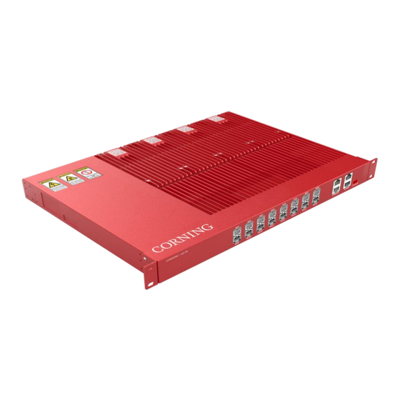
PS-MP is a dual port digital transport platform supporting public safety coverage on fibre
optic cable using the CPRI protocol. It adopts Feed-Forward Technology, allowing for
deployment of legacy narrow band solutions while still benefiting from the digital
transmission and filtering functionality. This platform is ideal for P25, DMR, PMR, GSM-R &
Tetra technology either as standalone or complimentary with wideband cellular deployments.
The PS-MP system supports programmable band or channel selective. The PS-MP supports
up to 37 dBm output per ban. The PS-MP converts an optical signal to RF and then transmits
at the relevant band and receives the analog RF signal, conditions it, and converts it back to
optical for routing to the PS-AU.
This document describes the User Manual for the PS-MP unit.
This is NOT a CONSUMER device. It is designed for installation by FCC LICENSEES and
QUALIFIED INSTALLERS. You MUST have an FCC LICENSE or express consent of an FCC
License to operate this device. NOTE: Only authorized person can enter the area where the
antenna is installed. And the person is fully aware of the potential for exposure and can exercise
control over his or her exposure by leaving the area or by some other appropriate means.
Awareness of the potential for RF exposure in a workplace or similar environment can be provided
through specific training as part of a RF safety program.
Corning Optical Communications
Medium-Power (PS-MP/PS-AU-AIR)
User Programming Manual
Public Safety
User Manual | Page 1
Advertisement
Table of Contents

Related Manuals for CORNING PS-MP


Summary of Contents for CORNING PS-MP
- Page 1 The PS-MP system supports programmable band or channel selective. The PS-MP supports up to 37 dBm output per ban. The PS-MP converts an optical signal to RF and then transmits at the relevant band and receives the analog RF signal, conditions it, and converts it back to optical for routing to the PS-AU.
-
Page 2: Table Of Contents
NSTALLATION PS-AU M ................................19 OUNTING IMENSION PACING RF C ........................................ 20 ONNECTION 5. INSTALLING THE REMOTE UNIT (PS-MP) ............................21 PS-MP A ......................................21 CCESSORIES ) ................................22 NSTALLATION ACK ON THE ) ................................29 NSTALLATION IDE ON THE PS-MP W .............................. - Page 3 PS-MP M ................................42 OUNTING IMENSION PACING 6. OPTICAL CONNECTION .................................. 43 ................................... 43 PTICAL RANSCEIVER ODULE Single Port Bidirectional SFP Transceiver ..............................43 Dual Port SFP Transceiver ..................................43 Optical Indicator ....................................... 44 Corning Optical Communications User Manual | Page 3...
-
Page 4: Preface
PS-MP is not a consumer product. Please install and use PS-MP in accordance with the instructions. ⚫ Before installing or modifying any PS-MP equipment, read and fully understand the entire instructions in this guide. ⚫ Only qualified personnel are authorized to install and maintain the PS-MP. -
Page 5: Environmental Considerations
Maximum humidity: 85% PS-AU Operating Temperature range: -10° C to +50° C PS-MP Operating Temperature range: -40° C to +50° C Storage Temperature range: -40° C to +70° C Warning Marks The warning marks on the CrossFire shell should be kept clean, readable, and identifiable. - Page 6 For performance and safety reasons, NEVER disassemble and remodel the devices. Corning Optical Communications User Manual | Page 6...
-
Page 7: Installation Preparation
Open the packing container carefully. The device is contained in a protective package inside the packing container; however, caution is still necessary so as not to damage the internal package and device. Remove the internal package from the packing container. Unpack the device from the internal package carefully. Corning Optical Communications User Manual | Page 7... -
Page 8: Verifying The Contents
Note: Only maintenance personnel or users who understand the reason for access and are experienced with restricted area access and understand the necessary preventive measures should access the installation site. Corning Optical Communications User Manual | Page 8... -
Page 9: Installation Tools
Ground the device with the grounding screw located next to the power socket. See more details in the following ⚫ chapters. Do not use the grounding screw to connect external devices. ⚫ Corning Optical Communications User Manual | Page 9... -
Page 10: Installing The Access Unit (Ps-Au)
4. Installing the Access Unit (PS-AU) Accessories List Corning Optical Communications User Manual | Page 10... -
Page 11: Rack Installation
To install the Access Unit in the equipment rack. Attach the 19" mounting brackets at the front of the PS-AU, using 4 screws M3×6 per bracket and the Phillips screwdriver. Observe the orientation of the brackets. Corning Optical Communications User Manual | Page 11... - Page 12 Recommended attaching the sliding rails to rack. (Not included in delivery). Corning Optical Communications User Manual | Page 12...
- Page 13 Place the PS-AU in the rack and secure the PS-AU using 2 screws M6×16 on both sides and the Phillips screwdriver. Corning Optical Communications User Manual | Page 13...
- Page 14 1 rack unit (44mm) of free space below each unit with fan occupied in the middle. Otherwise, the device temperature may rise and affect the service life of the device. Corning Optical Communications User Manual | Page 14...
- Page 15 Connect and lock the power cable at the PS-AU rear side. Connect and screw the ground wire at the PS-AU rear side. Corning Optical Communications User Manual | Page 15...
-
Page 16: Wall Installation
To install the Access Unit on the wall: Rotate the handles 90° and attach them at the rear of the PS-AU, using 4 screws M3×6 per bracket and the Phillips screwdriver. Observe the orientation of the brackets. Corning Optical Communications User Manual | Page 16... - Page 17 Mark 4 x ∅6.8mm drilling holes sites for the hanger to be attached to the wall. Drill 4 holes at the marked sites using percussion drill and embed 4×∅10 plastic expansion pipes. Note: H=70mm. Fasten the case with 4×M6 expansion bolt. Corning Optical Communications User Manual | Page 17...
- Page 18 Connect and lock the power cable at the PS-AU rear side Connect and screw the ground wire at the PS-AU rear side Corning Optical Communications User Manual | Page 18...
-
Page 19: Ps-Au Mounting Dimension Spacing
PS-AU Mounting Dimension Spacing Corning Optical Communications User Manual | Page 19... -
Page 20: Rf Connection
Interface Name Description Module 4 Duplexer Interface QMA Female Module 3 Duplexer Interface QMA Female Module 2 Duplexer Interface QMA Female Module 1 Duplexer Interface QMA Female Electric Power Line Interface Grounding Corning Optical Communications User Manual | Page 20... -
Page 21: Installing The Remote Unit (Ps-Mp)
5. Installing the Remote Unit (PS-MP/PS-AU-AIR) Accessories Note: PS-AU-AIR installation is same as PS-MP installation Corning Optical Communications User Manual | Page 21... -
Page 22: Wall Installation (Back On The Wall)
Wall Installation (Back on the Wall) Attach and fasten the handle to the side of PS-MP with screws M6×14 using T5 Wrench. Attach and fasten the Bracket I to the back of PS-MP with screws M6×14 using T5 Wrench. Corning Optical Communications... - Page 23 Drill 4 holes at the marked positions. Note: H=70mm Attach the dowels, expansion screws or the like and fasten the Bracket II to the wall. Tips: use Bracket II as a reference to control each devices’ separation distance before hanging and locking PS-MP up. Corning Optical Communications...
- Page 24 Hang the PS-MP on the mounting bracket II and fasten with nuts M10. Corning Optical Communications User Manual | Page 24...
- Page 25 Fasten the Bracket I and II with screws M6×14. Corning Optical Communications User Manual | Page 25...
- Page 26 Connect and lock the power cable Connect and screw the ground cable Corning Optical Communications User Manual | Page 26...
- Page 27 Connect and tighten the waterproof network cable Corning Optical Communications User Manual | Page 27...
- Page 28 Connect and tighten the waterproof optical fibre Corning Optical Communications User Manual | Page 28...
-
Page 29: Wall Installation (Side On The Wall)
Wall Installation (Side on the Wall) Corning Optical Communications User Manual | Page 29... - Page 30 Attach and fasten the handle to the side of PS-MP with screws M6×14 using T5 Wrench. Attach and fasten the Bracket I to the left side of PS-MP with screws M6×14 using T5 Wrench. Corning Optical Communications User Manual | Page 30...
- Page 31 Drill 4 holes at the marked positions. Note: H=70mm. Attach the dowels, expansion screws or the like and fasten the Bracket II to the wall. Tips: use Bracket II as a reference to control each devices’ separation distance before hanging and locking PS-MP up. Corning Optical Communications...
- Page 32 Hang the PS-MP on the mounting bracket II and fasten with nuts M10. Corning Optical Communications User Manual | Page 32...
- Page 33 Fasten the Bracket I and II with screws M6×14. Corning Optical Communications User Manual | Page 33...
- Page 34 Connect and lock the power cable Connect and screw the ground cable Corning Optical Communications User Manual | Page 34...
-
Page 35: Ps-Mp Wall Mounting Dimension Spacing
PS-MP/PS-AU-AIR Wall Mounting Dimension Spacing Corning Optical Communications User Manual | Page 35... -
Page 36: Pole Installation
Install the handle and Bracket I to the back of PS-MP. Install the bracket II and Bracket III to the pole. Hang the PS-MP on the mounting bracket and fasten with nuts M10. Connect the ground cable and power cable. -
Page 37: Rack Installation
Rack Installation Corning Optical Communications User Manual | Page 37... - Page 38 Attach and fasten the Bracket III to the Standard 19’ Rack with screws Note: Please purchase Bracket III for rack installation separately. Corning Optical Communications User Manual | Page 38...
- Page 39 Attach and fasten the handle to the side of PS-MP with screws M6×14 using T5 Wrench. Attach and fasten the Bracket I to the back of PS-MP with screws M6×14 using T5 Wrench. Corning Optical Communications User Manual | Page 39...
- Page 40 Hang the PS-MP on the mounting bracket and fasten with nuts M10. Corning Optical Communications User Manual | Page 40...
- Page 41 Connect the ground cable and power cable. Connect and screw the ground cable Corning Optical Communications User Manual | Page 41...
-
Page 42: Ps-Mp Mounting Dimension Spacing
PS-MP Mounting Dimension Spacing Corning Optical Communications User Manual | Page 42... -
Page 43: Optical Connection
A should correspond to the transmitter of B. The optical receiver and transmitter terminals of the optical module can be determined by the triangular mark on the optical module. The triangular mark in the yellow box and the red and blue lines indicate the optical fibre connections. Corning Optical Communications User Manual | Page 43... -
Page 44: Optical Indicator
Figure below. When the optical module is unplugged or not synchronized, the indicators are red as shown in the left pair of indicators. Check whether both indicators turn green after connecting one pair of optical modules. If the indicators are red, the terminal has not synchronized. Corning Optical Communications User Manual | Page 44... - Page 45 —Increase the separation between the equipment and receiver. —Connect the equipment into an outlet on a circuit different from that to which the receiver is connected. —Consult the dealer or an experienced radio/TV technician for help. Corning Optical Communications User Manual | Page 45...
- Page 46 Corning Optical Communications LLC • 4200 Corning Place • Charlotte, NC 28216 USA 800-743-2675 FAX: 828-325-5060 • International: +1-828-901-5000 • www.corning.com/opcomm Corning Optical Communications reserves the right to improve, enhance, and modify the features and specifications of Corning Optical Communications products without prior notification. A complete listing of the trademarks of Corning Optical Communications is available at www.corning.com/opcomm/trademarks.
Need help?
Do you have a question about the PS-MP and is the answer not in the manual?
Questions and answers