CORNING Centrix Manual
System pigtailed housing with pigtailed cassette installation
Hide thumbs
Also See for Centrix:
- Jumper routing (20 pages) ,
- Installation instruction (16 pages) ,
- Instructions manual (8 pages)
Table of Contents
Advertisement
Quick Links
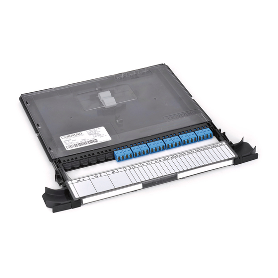
Centrix™ System Pigtailed Housing
with Pigtailed Cassette Installation
P/N 003-949
Issue 7
rrelated literature | Search www.corning.com/opcomm.
003-948
003-950
003-951
003-959
003-960
003-961
Table of Contents
1.
General . . . . . . . . . . . . . . . . . . . . . . . . . . . . . . . . . . . . . . . . . . . . . . . . . . . . . . . . . . . . . . . . . . . . . . . . . . . . . . . . . . . . . . . . . . . . . . . . . . .1
2.
Carton Contents . . . . . . . . . . . . . . . . . . . . . . . . . . . . . . . . . . . . . . . . . . . . . . . . . . . . . . . . . . . . . . . . . . . . . . . . . . . . . . . . . . . . . . . . . . .1
3.
Tools and Materials Required . . . . . . . . . . . . . . . . . . . . . . . . . . . . . . . . . . . . . . . . . . . . . . . . . . . . . . . . . . . . . . . . . . . . . . . . . . . . . . .1
4.
Installation . . . . . . . . . . . . . . . . . . . . . . . . . . . . . . . . . . . . . . . . . . . . . . . . . . . . . . . . . . . . . . . . . . . . . . . . . . . . . . . . . . . . . . . . . . . . . . 2
4.1
Prepare Distribution Cable (900 micron and ribbon) 4-, 6-, 8-, and 12- ber for Cable Strain-Relief . . . . . . . . . 2
4.1.1
Braided Tubing Application . . . . . . . . . . . . . . . . . . . . . . . . . . . . . . . . . . . . . . . . . . . . . . . . . . . . . . . . . . . . . . . . . .5
4.1.2
Transport Tubing Application . . . . . . . . . . . . . . . . . . . . . . . . . . . . . . . . . . . . . . . . . . . . . . . . . . . . . . . . . . . . . . . . .7
4.2
Organize Distribution Cables . . . . . . . . . . . . . . . . . . . . . . . . . . . . . . . . . . . . . . . . . . . . . . . . . . . . . . . . . . . . . . . . . . . . . . . . 8
5.
Connect Fiber (Loose Tube or Ribbon) in the Rear Cable Access Frame . . . . . . . . . . . . . . . . . . . . . . . . . . . . . . . . . . . . . . . . . 9
6.
Connect Fiber in the Front Cable Access Frame . . . . . . . . . . . . . . . . . . . . . . . . . . . . . . . . . . . . . . . . . . . . . . . . . . . . . . . . . . . . . .17
6.1
Splice Loose Tube Fibers . . . . . . . . . . . . . . . . . . . . . . . . . . . . . . . . . . . . . . . . . . . . . . . . . . . . . . . . . . . . . . . . . . . . . . . . . . . . .17
6.2
Splice Ribbon Fibers . . . . . . . . . . . . . . . . . . . . . . . . . . . . . . . . . . . . . . . . . . . . . . . . . . . . . . . . . . . . . . . . . . . . . . . . . . . . . . . 25
7.
Manage Cable Slack . . . . . . . . . . . . . . . . . . . . . . . . . . . . . . . . . . . . . . . . . . . . . . . . . . . . . . . . . . . . . . . . . . . . . . . . . . . . . . . . . . . . . 34
8.
Maintenance . . . . . . . . . . . . . . . . . . . . . . . . . . . . . . . . . . . . . . . . . . . . . . . . . . . . . . . . . . . . . . . . . . . . . . . . . . . . . . . . . . . . . . . . . . . . 34
9.
Connector Care and Cleaning . . . . . . . . . . . . . . . . . . . . . . . . . . . . . . . . . . . . . . . . . . . . . . . . . . . . . . . . . . . . . . . . . . . . . . . . . . . . . 35
9.1
Clean Jumpers . . . . . . . . . . . . . . . . . . . . . . . . . . . . . . . . . . . . . . . . . . . . . . . . . . . . . . . . . . . . . . . . . . . . . . . . . . . . . . . . . . . . 35
9.2
Clean Pigtails . . . . . . . . . . . . . . . . . . . . . . . . . . . . . . . . . . . . . . . . . . . . . . . . . . . . . . . . . . . . . . . . . . . . . . . . . . . . . . . . . . . . . 36
1.
General
It is assumed that the Centrix™ System housings have already been installed into the frame in accordance with the
instructions provided with each housing.
2.
Carton Contents
• Centrix System pigtailed housing
3.
Tools and Materials Required
• Screwdriver
• Centrix System pigtailed cassettes (purchased separately)
Centrix System Housing Installation
Centrix System Frame Installation
Centrix System Stubbed Housing Installation
Centrix System Pigtailed Cassette installation with WDMs and PON Devices
Centrix System Jumper Routing Guidelines
Centrix System Accessories Installation
Click on "Resources/Standard Recommended Procedures."
Standard Recommended Procedure 003-949 | Issue 7 | October 2017 | Page 1 of 37
Advertisement
Table of Contents

Related Manuals for CORNING Centrix


Summary of Contents for CORNING Centrix
-
Page 1: Table Of Contents
Clean Pigtails ..................36 General It is assumed that the Centrix™ System housings have already been installed into the frame in accordance with the instructions provided with each housing. -
Page 2: Installation
Installation CAUTION: Recommend the use of safety glasses (spectacles) conforming to ANSI Z87, for eye protection from accidental injury when handling chemicals, cables, or working with ber. Pieces of glass ber are very sharp and have the potential to damage the eye. CAUTION: The wearing of cut-resistant safety gloves to protect your hands from accidental injury when using sharp-bladed tools and armored cable is strongly recommended. - Page 3 Step 1: Measure from bottom of housing in which the cassette to be terminated is located. Cut cable per the strip length measurement in Figure 2. Figure 2 Step 2: Strain-relieve cable as shown in Figure 3 for the appropriate frame - rear or front cable access. An optional universal cable clamp (UCC) (purchased separately - UCC-001) may be used to manage large cables.
- Page 4 Figure 4 Step 3: Cut away sheath to 25 mm (1 in) past the strain-relief point at the housing (Figure 4). Step 4: Remove core wrap and strength member, where applicable. Step 5: Divide bers into groups as detailed in Table 1 to feed the cassettes, depending on the number of connectors in the cassette.
-
Page 5: Braided Tubing Application
NOTE: Remove all sheathing to the strain-relief location on the housing. Replace the inner sheathing with transport/braided tubing. This applies only to unstubbed cassettes and provides room to dress bers back into the cassettes once the frame is fully loaded. Step 6: Determine length of tubing by measuring from the cassette to the end of the cable sheath. - Page 6 Step 4: Push the tube up to the cable sheath (Figure 8). Figure 8 Step 5: Insert braided tubes under slit in sheath (Figure 9). Figure 9 Step 6: Tape joint and cover with heat-shrink tubing (Figure 10). IMPORTANT: Taping to 25 mm (1 in) is important to protect braided tubing from heat. DO NOT heat the braided tube to avoid damage to the tubing.
-
Page 7: Transport Tubing Application
Step 7: Gently remove the extra slack in the braided tubing by sliding your hand down the braided tube (Figure 11). Do NOT pull on braided tubing! Figure 11 Step 8: Remove plastic rod (Figure 12) and reuse, if necessary. Step 9: Tape braided tubing end. -
Page 8: Organize Distribution Cables
Step 3: Tape joint and cover with heat-shrink tubing (Figure 14). IMPORTANT: Taping to 25 mm (1 in) is important to protect transport tubing from heat. DO NOT heat the transport tube to avoid damage to the tubing. Figure 14 Organize Distribution Cables As distribution cables exit the frame, organize them on the brackets or lances appropriate for the cable entry location. -
Page 9: Connect Fiber (Loose Tube Or Ribbon) In The Rear Cable Access Frame
Step 2: Place the cassette on a work surface. NOTE: To facilitate splicing and testing, Corning o ers a work shelf (CTX-WORKSHELF) shown in Figure 17. Figure 17 Standard Recommended Procedure 003-949 | Issue 7 | October 2017 | Page 9 of 37... - Page 10 NOTE: The cassette service bracket (CTX-SERVICE-BKT), shown in Figure 18, facilitates ber routing and splicing. Refer to SRP 003-961 for instructions on their use. Figure 18 Step 3: If using the service bracket, place the cassette on it as shown in Figure 18. Then insert the service bracket into the slot vacated by the cassette being work on (Figure 19).
- Page 11 Step 5: Secure the end of the transport/braided tube holding the input ribbon or loose tube bers in the strain-relief holder (Figure 20). Press the strain-relief tab closed to secure the bers. Figure 20 NOTE: When placing spliced bers in the splice organizer, it may be necessary to lift the organizer and rotate it 90 degrees from its factory-installed orientation (Figure 21).
- Page 12 Step 6: Uncoil two loops of pigtail ribbon or bers from inside the cassette (Figure 22).Do NOT lift the plastic shield or remove bers from beneath it. Step 7: Bring all input ribbon or bers as a group into the internal ber routing area in front of the pigtail bers.
- Page 13 Step 11: Bring input bers into the splice organizer on one side of the organizer (Figure 24). Step 12: Continue routing pigtail bers to the other side of the splice organizer. Step 13: Line up the bers being sure to maintain the color orientation. Figure 24 Step 14: Cut the ribbons/ bers at the outer edge of the splice organizer (Figure 24).
- Page 14 Step 21: Close the front cassette cover. Ensure that the snap features click when closing to securely latch the cover. Step 22: x the designation label to the handle (Figure 26), if it is not already attached. Figure 26 Step 23: If using the cassette service bracket, pull the plunger on the side and lift the cassette o the service bracket (Figure 27).
- Page 15 Step 28: If the service bracket was used, remove it from the slot where the cassette will be inserted. Fold the service bracket (Step 29) and store it in the service shelf in the center of the Centrix™ System frame.
- Page 16 Step 30: Insert cassette into the housing, starting at the top of the housing (Figure 30). Step 31: Continue loading cassettes until the housing is full. Figure 30 Step 32: Reinstall rear troughs if they were previously removed. Pull out the plungers on each side of the trough. Lift the trough’s hanging tabs up and slide the tabs into the slots in the frame.
-
Page 17: Connect Fiber In The Front Cable Access Frame
Step 2: Turn cassette over to access the bottom and move it to a work surface or work shelf. NOTE: To facilitate splicing and testing, Corning o ers a work shelf (CTX-WORKSHELF) shown in Figure 33. Figure 33 Standard Recommended Procedure 003-949 | Issue 7 | October 2017 | Page 17 of 37... - Page 18 Step 3: Open the hinged covers (Figure 34). Bring the input bers into the side of the cassette and out the rear in preparation for splicing on the front side. Close the hinged covers on back. Figure 34 NOTE: The cassette service bracket (CTX-SERVICE-BKT), shown in Figure 35, facilitates ber routing and splicing. Refer to SRP 003-961 for instructions on their use.
- Page 19 Step 4: If using the service bracket, place the cassette on it as shown in Figure 35. Then insert the service bracket into the slot vacated by the cassette being work on (Figure 36). Open the cover of the cassette and remove it, if desired, by bowing the hinged edge of the cover to release the hinge pins.
- Page 20 Step 5: Secure the end of the transport tube holding the input bers in the strain-relief holder (Figure 37). Press the strain-relief tab closed to secure the bers. Figure 37 NOTE: When placing spliced bers in the splice organizer, it may be necessary to lift the organizer and rotate it 90 degrees from its factory-installed orientation (Figure 38).
- Page 21 Step 6: Reroute last loop of the pigtail ber to the outer path before bringing it back to the splice organizer. Cut the bers at the outer edge of the splice organizer (Figure 39). Figure 39 Step 7: Slide a splice protector onto either the input bers or onto the pigtail bers. Step 8: Bring the input bers and the pigtail bers to the splicer and splice per standard practices.
- Page 22 Step 12: Close the front cassette cover. Ensure that the snap features click when closing to securely latch the cover. Step 13: x the designation label to the handle (Figure 41), if necessary. Figure 41 Step 14: If using the cassette service bracket, pull the plunger on the side and lift the cassette o the service bracket (Figure 42).
- Page 23 Step 15: Remove the service bracket from the slot where the cassette will be inserted. Fold the service bracket (Figure 43) and store it in the service shelf in the center of the Centrix™ System frame. Figure 43 Standard Recommended Procedure 003-949 | Issue 7 | October 2017 | Page 23 of 37...
- Page 24 Step 16: Turn cassette over and move it to a work surface or the work shelf shown in Figure 33. Open the slack storage covers (Figure 44) on the bottom of the cassette. Step 17: Place the transport tubing around the perimeter of the cassette underneath the restraint tabs. Figure 44 Step 18: Close the slack storage covers.
-
Page 25: Splice Ribbon Fibers
Step 2: Turn cassette over to access the bottom and move it to a work surface or work shelf. NOTE: To facilitate splicing and testing, Corning o ers a work shelf (CTX-WORKSHELF) shown in Figure 47. Figure 47 Standard Recommended Procedure 003-949 | Issue 7 | October 2017 | Page 25 of 37... - Page 26 Step 4: Turn the cassette over to the front side. Step 5: Place the cassette on a work surface. To facilitate splicing and testing, Corning o ers a work shelf (CTX-WORKSHELF) and a cassette service bracket (CTX-SERVICE-BKT), shown in Figure 49. Refer to SRP 003-961 for instructions on their use.
- Page 27 Step 6: If using the service bracket, insert it into the slot vacated by the cassette being work on (Figure 50). Open the cover of the cassette and remove it, if desired, by bowing the hinged edge of the cover to release the hinge pins.
- Page 28 Step 7: Secure the end of the transport tube holding the input bers in the strain-relief holder (Figure 52). Press the strain-relief tab closed to secure the bers. Figure 52 NOTE: When placing spliced bers in the splice organizer, it may be necessary to lift the organizer and rotate it 90 degrees from its factory-installed orientation (Figure 53).
- Page 29 Step 8: Uncoil two loops of pigtail bers from inside the cassette (Figure 54).Do NOT lift the plastic shield or remove bers from beneath it. Step 9: Bring all input bers as a group into the internal ber routing area in front of the pigtail bers. Figure 54 Step 10: Gather the input and pigtail bers with all the input bers to the inside of the pigtail bers.
- Page 30 Step 12: Continue routing input bers and pigtails as a unit inside the ber routing area. Step 13: Bring input bers into the splice organizer on one side of the organizer (Figure 56). Step 14: Continue routing pigtail bers to the other side of the splice organizer. Step 15: Line up the bers being sure to maintain the color orientation.
- Page 31 Step 23: Close the front cassette cover. Ensure that the snap features click when closing to securely latch the cover. Step 24: x the designation label to the handle (Figure 58), if necessary. Figure 58 Step 25: If using the cassette service bracket, pull the plunger on the side and lift the cassette o the service bracket (Figure 59).
- Page 32 Step 26: Remove the service bracket from the slot where the cassette will be inserted. Fold the service bracket (Figure 60) and store it in the service shelf in the center of the Centrix™ System frame. Figure 60 Standard Recommended Procedure 003-949 | Issue 7 | October 2017 | Page 32 of 37...
- Page 33 Step 27: Turn cassette over and move it to a work surface or the work shelf shown in Figure 60. Step 28: Open the slack storage covers (Figure 61) on the bottom of the cassette. Step 29: Place the transport tubing around the perimeter of the cassette underneath the restraint tabs. Figure 61 Step 30: Close the slack storage covers.
-
Page 34: Manage Cable Slack
Manage Cable Slack Arrange transport/bu er tubing slack as shown for rear or front cable access (Figure 63). Figure 63 Maintenance CAUTION: Fiber optic cable is sensitive to excessive pulling, bending and crushing forces. Consult the cable speci cation sheet for the cable you are installing. Do not bend the cable more sharply than the minimum recommended bend radius. -
Page 35: Connector Care And Cleaning
Connector Care and Cleaning WARNING: Never look directly into the end of a ber that may be carrying laser light. Laser light can be invisible and can damage your eyes. Viewing it directly does not cause pain. The iris of the eye will not close involuntarily as when viewing a bright light. -
Page 36: Clean Pigtails
Step 4: Disconnect jumpers as required. Clean adapters and connectors per standard company practices or as described in Section 9. Reconnect jumpers (Figure 65 left). Step 5: Raise handle. Dress jumper cords to the side of the cassette (Figure 65 right). Step 6: Close handle cover. - Page 37 A complete listing of the trademarks of Corning Optical Communications is available at www.corning.com/opcomm/trademarks. All other trademarks are the properties of their respective owners. Corning Optical Communications is ISO 9001 certi ed. © 2013, 2017 Corning Optical Communications. All rights reserved.
Need help?
Do you have a question about the Centrix and is the answer not in the manual?
Questions and answers