Elesa DD51-E Operating Instruction
Electronic position indicators
Hide thumbs
Also See for DD51-E:
- Instructions for use manual (31 pages) ,
- Operating instructions manual (30 pages) ,
- Instructions for use (5 pages)
Table of Contents
Advertisement
Quick Links
Advertisement
Table of Contents

Related Manuals for Elesa DD51-E


Summary of Contents for Elesa DD51-E
- Page 1 DD51-E DD51-E-RF Electronic position indicators OPERATING INSTRUCTION...
-
Page 2: Table Of Contents
DD51-E - DD51-E-RF Contents 1. Safety Instructions Release Informations 2. System description Wireless devices network 3. Assembly 4. Symbols on the display 5. Key function 6. Turning on the system Turning off the system 7. Operating mode Absolute / incremental measuring... - Page 3 DD51-E - DD51-E-RF RF version (DD51-E-RF) 7.6.1 Programming the network parameter (nEtid) and the channel parameter (nEtch) 7.6.2 Targets 8. Programming mode Programming parameters with numeric values Device parameters (in alphabetic order) Main menu tree Target menù tree Parameter value Addittional features 8.6.1 Reset...
-
Page 4: Safety Instructions
DD51-E - DD51-E-RF 1 Safety Instructions The product has been designed and manufactured in accordance with the current regulations. The product lea- ves the factory ready for use and complies with the safety standards. To maintain the product in this state, it is necessary that it... -
Page 5: Release Informations
Tampering with this product may endanger the correctness and accuracy of its operation. In case of malfunction, do not attempt any repairs to the units and contact Elesa sales office. 1.1 Release Informations Even if almost all the functionalities are the same as in the previous releases, the maual refer to devices with release higher than 5.01.00 (see cap. -
Page 6: System Description
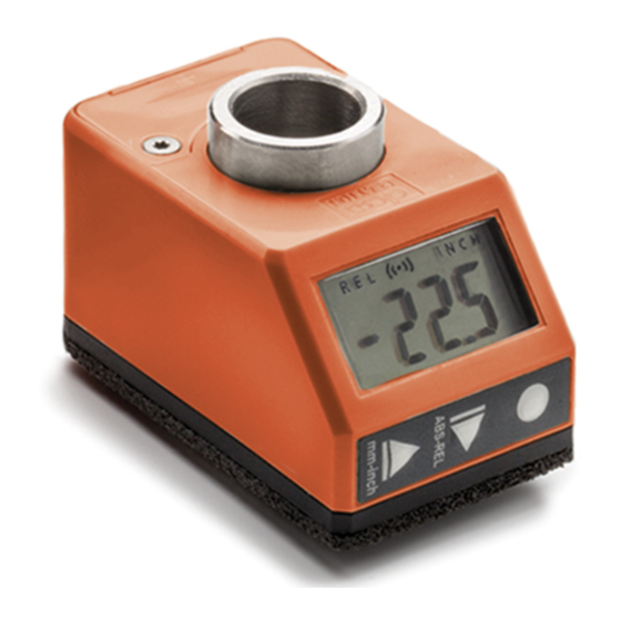
DD51-E - DD51-E-RF 2 System description DD51-E position indicators, with battery power supply, can be used on passing through shafts in any position to provide the reading of the absolute or incremental positioning of a machine component. Mechanical and electrical characteristics Power supply Lithium battery CR2450 3.0 V... -
Page 7: Wireless Devices Network
PLC. The Elesa’s wireless network is made by the following components: - One control unit UC-RF - Max 36 electronic position indicators or meter as DD51-E-RF, DD52R-E-RF or MPI-R10-RF Target positions Current positions The control unit UC-RF is provided with a standard interface... -
Page 8: Symbols On The Display
DD51-E - DD51-E-RF 4 Symbols on the display 1. Relative mode indicator 2. Low battey level indicator 3. RF connection indicator 4. Unit of measure (mm / inch) 5. Unit of measure (degrees) 6. Target position indications 5 Key function WARNINGS! The keys’... - Page 9 DD51-E - DD51-E-RF Select the: Absolute measuring mode Incremental measuring mode It is possible to choose one of the following options (see voice of the _ _ 0 _ _ menu – cap. 8.3): Digit increase / ArCLr [DEFAULT]: programming...
-
Page 10: Turning On The System
DD51-E - DD51-E-RF Programmable with one of the following options (see voice of the _ _ 0 _ 0 menu – cap. 8.3): L_OrG [DEFAULT]: the key combination sets the absolute value to the sum of the parameters Origin and Offset. -
Page 11: Unit Of Measure Selection
DD51-E - DD51-E-RF If the absolute measuring mode is selected no symbol is show on the display. It is possible to change the key function _ _ 0 _ _ chosing one of the available otions in the menu voice _ _ 0 _ _... -
Page 12: Setting The Absolute Reference
DD51-E - DD51-E-RF 7.3 Setting the absolute reference After having selected the absolute measuring mode and stopped the shaft in the starting position or in the reference position, press the key combination to set the absolute value to the sum of the values of the parameters OrG (absolute value of reference) and the selected OFFS (compensation value). -
Page 13: Direct Programming Of The Absolute
For programming the parameters listed above see parameter 0 _ _ _ 0 of cap. 8.3. 7.5 Targets DD51-E allow to set up to 32 target positions to store relevant machine configuration setting. To program the targets: - selet tArGE in the main menu (see cap. 8.3) - select PrOGt (see cap. -
Page 14: Reaching The Target Position
DD51-E - DD51-E-RF To load a target: - select tArGE in the main menu (see cap. 8.3) - select LOAdt (see cap. 8.4) LtG32 - select the wanted target value ( LtG01 to ) using the keys - press the key to select. -
Page 15: Target Display Mode
7.5.3 Target tolerance Set the value of Ptoll parameter to define the tollerance allowed for target (see cap. 8 for details). 7.6 RF version (DD51-E-RF) 7.6.1 Programming the network parameter (nEtid) and the channel parameter (nEtch) The system radio network is defined by the following two... -
Page 16: Targets
DD51-E - DD51-E-RF 7.6.2 Targets Using DD51-E-RF, target positions can be sent from the PLC to the indicators through the control unit. When a target is set, the behaviour is the sameas decribed in cap. 7.5. 8 Programming mode Press the key for 3 seconds to enter the programming mode. -
Page 17: Device Parameters
DD51-E - DD51-E-RF 8.2 Device parameters (in alphabetic order) Standard Parameter Description Available options value Measurement --o counterclockwise direction rotation to increment Set direction the measure of the positive o-- clockwise rotation axis to increment the measure diSP Display 0°... -
Page 18: Main Menu Tree
DD51-E - DD51-E-RF Standard Parameter Description Available options value StEP Reading 0.01 ; 100.00 001.00 after one revolution Display _ _ _ _ 0 d_toG0 : during the visualization “ t_Sho ” positioning the display during target show the distance from mode the target. - Page 19 DD51-E - DD51-E-RF 0° diSP 180° SPEEd 1000 nEt id rAdio ch 01 nEt ch ch 36 0.01 ÷ 9.99 PtoLL Inch 0.001 ÷ 0.393 tArGE See Cap. 8.4 0 _ _ _ _ nodEG ArCLr _ _ 0 _ _...
-
Page 20: Target Menù Tree
DD51-E - DD51-E-RF 8.4 Target menù tree StoP_t PtG 01 See Cap. 8.5 PrOG_t PtG 32 See Cap. 8.5 LtG 01 LOAd_t LtG 32 * Displayed only if a target position is setted 8.5 Parameter value The parameter value depends on the unit of measure and resolution set. -
Page 21: Addittional Features
As last voice in the main menu, starting with the “ r ” letter, are shown the release data of the device that can be scrolled pressing the key Please note these values and communicate them to Elesa in case of support needed. 8.6.4 Password It is possible to avoid the unwanted access to the device menu by choosing “... -
Page 22: Problem Solving
DD51-E - DD51-E-RF To simply remove the battery from the battery compartment, we recommend the use of a magnet. By replacing the battery in less than 5 seconds, all the measurement and settings wil not be lost. If more time is required and the display turns off, the settings of the device have to be set or verified again. - Page 23 DD51-E - DD51-E-RF EU DECLARATION OF CONFORMITY (DOC) COMPANY NAME: Elesa S.p.a. POSTAL ADDRESS: Via Pompei 29 POSTCODE AND CITY: 20900 Monza TELEPHONE NUMBER: +39 039 28111 E-MAIL ADDRESS: info@elesa.com Declare that the DoC is issued under our sole responsibility and belongs to the following product:...
- Page 24 DD51-E - DD51-E-RF EU DECLARATION OF CONFORMITY (DOC) COMPANY NAME: Elesa S.p.a. POSTAL ADDRESS: Via Pompei 29 POSTCODE AND CITY: 20900 Monza TELEPHONE NUMBER: +39 039 28111 E-MAIL ADDRESS: info@elesa.com Declare that the DoC is issued under our sole responsibility and belongs to the following product:...
- Page 26 ELESA S.p.A. Via Pompei, 29 20900 Monza (MB) Italy phone +39 039 28111 fax +39 039 836351 info@elesa.com www.elesa.com...
Need help?
Do you have a question about the DD51-E and is the answer not in the manual?
Questions and answers