Elesa DD52R-E Operating Instructions Manual
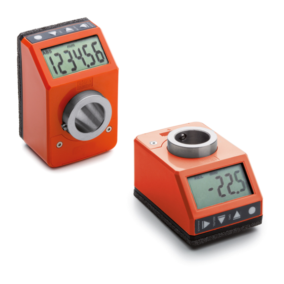
Electronic position indicators
Hide thumbs
Also See for DD52R-E:
- Instructions for use manual (31 pages) ,
- Instructions for use manual (73 pages) ,
- Operating instructions manual (30 pages)

Related Manuals for Elesa DD52R-E


Summary of Contents for Elesa DD52R-E
- Page 1 OPERATING INSTRUCTIONS Electronic position indicators DD52R-E (GN 9053)* DD52R-E-RF (GN 9153)* *(Product series valid only for Germany)
-
Page 2: Table Of Contents
Targets 7.5.1 Reaching the target position 7.5.2 Display target mode 7.5.3 Target tolerance RF version (DD52R-E-RF) 7.6.1 Programming the network parameter (nEt id) and the channel parameter (nEt ch) 7.6.2 Targets Modelle, alle Rechte vorbehalten in Übereinstimmung mit dem Gesetz. - Page 3 DD52R-E - DD52R-E-RF (GN 9053) (GN 9153) 8. Programming mode Programming parameters with numeric values Device parameters (in alphabetic order) Main menu tree Target menu tree Parameter value Additional features 8.6.1 Reset 8.6.2 Test LCD 8.6.3 Release version 8.6.4 Password 9.
-
Page 4: Safety Instructions
DD52R-E - DD52R-E-RF (GN 9053) (GN 9153) 1 Safety Instructions The product has been designed and manufactured in accordance with the current regulations. The product leaves the factory ready for use and complies with the safety standards. To maintain the product in this state, it is necessary that it is assembled and used properly, in the closest compliance with this instruction manual and with the following specific safety precautions. -
Page 5: Release Information
Do not open or modify the case of the indicator. Tampering with this product may endanger the correctness and accuracy of its operation. In case of malfunction, do not attempt any repair to the units and contact Elesa sales office. -
Page 6: System Description
(GN 9053) (GN 9153) 2 System description The electronic position indicators DD52R-E, with battery power supply, can be used on passing through shafts in any position to provide the reading of the absolute or incremental positioning of a machine component. -
Page 7: Wireless Devices Network
PLC and the electronic position indicators DD52R-E-RF. The control unit UC-RF exchanges information with the electronic position indicators DD52R-E-RF via radio frequency and allows the setting of the target position and the control of the current position of each indicator, directly from the PLC. -
Page 8: Symbols On The Display
DD52R-E - DD52R-E-RF (GN 9053) (GN 9153) 4 Symbols on the display 1. Absolute / relative mode 2. Low battey level 3. Unit of measure (mm / inch / degrees) 4. RF connection 5. Target position indications 5 Key function... - Page 9 DD52R-E - DD52R-E-RF (GN 9053) (GN 9153) Select the: : absolute measuring mode : incremental measuring mode It is possible to choose one of the following options (see the voice of the _ _ 0 _ _ _ Digit decrease / menu –...
-
Page 10: Turning On The System
DD52R-E - DD52R-E-RF (GN 9053) (GN 9153) Programmable with one of the following options (see the voice of the _ _ _ 0 _ 0 menu – cap. 8.3): : the keys combination allows to tArGEt load/program one of the 32 target positions. -
Page 11: Operating Mode
DD52R-E - DD52R-E-RF (GN 9053) (GN 9153) 7 Operating mode 7.1 Absolute / incremental measuring mode selection Press the key to select the absolute or incremental measuring mode. The measuring mode selected is shown on the display by the symbols:... -
Page 12: Setting The Absolute Reference
DD52R-E - DD52R-E-RF (GN 9053) (GN 9153) 7.3 Setting the absolute reference After having selected the absolute measuring mode and stopped the shaft in the starting position or in the reference position, press the key combination to set the absolute value to the sum of the values of the parameters OrG (absolute reference value) and the selected OFFS (compensation value). -
Page 13: Targets
For programming the parameters listed above see parameter 0 _ _ _ _ 0 of cap. 8.3. 7.5 Targets The electronic position indicators DD52R-E allows the set up of 32 target positions to store relevant machine configuration setting. To program the targets: - selet tArGEt in the main menu (see cap. -
Page 14: Reaching The Target Position
DD52R-E - DD52R-E-RF (GN 9053) (GN 9153) PrOG_t : choose to program one of the 32 available target positions, then press to start programming. _ _ _ 0 _ 0 It is possible to change the function of the keys combination by... -
Page 15: Display Target Mode
DD52R-E-RF. Warning For the DD52R-E-RF with firmware release equal to 5.1 or higher, channel 1 is equivalent to channel 4 of the previous version. Consider it in case of use of the old system with UC-RF with fw release lower than 5.1. -
Page 16: Targets
(GN 9153) 7.6.2 Targets Using the electronic position indicators DD52R-E-RF, target positions can be sent from the PLC to the indicators through the control unit. When a target is set, the behaviour is the same as described in cap. 7.5. -
Page 17: Device Parameters (In Alphabetic Order)
DD52R-E - DD52R-E-RF (GN 9053) (GN 9153) 8.2 Device parameters (in alphabetical order) Parameter Description Available options Default Measurement --o counterclockwise rotation direction to increment the measure Set direction of the o-- clockwise rotation to positive axis incrememnt the measure 0°... -
Page 18: Main Menu Tree
DD52R-E - DD52R-E-RF (GN 9053) (GN 9153) Parameter Description Available options Default d_toG0 : during the positioning, the display shows the distance from the target. Keep the key pressed, on the display will appear the actual position of the indicator. - Page 19 DD52R-E - DD52R-E-RF (GN 9053) (GN 9153) nEt id rAdio ch 01 nEt ch ch 36 0.01 ÷ 9.99 P_toll Inch 0.001 ÷ 0.393 See Cap. 8.4 tArGEt 0 _ _ _ _ _ nodEG ArCLr _ _ 0 _ _ _...
-
Page 20: Target Menu Tree
DD52R-E - DD52R-E-RF (GN 9053) (GN 9153) 8.4 Target menù tree StoP_t See Cap. 8.5 PtG 01 PrOG_t See Cap. 8.5 PtG 32 LtG 01 LOAd_t LtG 32 * Displayed only if a target position is set 8.5 Parameter value The parameter value depends on the unit of measure and resolution set. -
Page 21: Test Lcd
By pressing the key other information aree shown, which have to be comunicated to Elesa staff in case the support needed. 8.6.4 Password It is possible to avoid free access to the device menu by choosing “ on “ in the PASS voice of the menu. -
Page 22: Problem Solving
DD52R-E - DD52R-E-RF (GN 9053) (GN 9153) 10 Problem solving Message on the Description Action display The system continues to measure Exceeding the reading scale displacements; (-199999; 999999). the value is shown on the display _ _ _ _ _ _... - Page 23 DD52R-E - DD52R-E-RF (GN 9053) (GN 9153) EU DECLARATION OF CONFORMITY (DOC) COMPANY NAME: Elesa S.p.a. POSTAL ADDRESS: Via Pompei 29 POSTCODE AND CITY: 20900 Monza TELEPHONE NUMBER: +39 039 28111 E-MAIL ADDRESS: info@elesa.com Declare that the DoC is issued under our sole responsibility and belongs to...
- Page 24 DD52R-E - DD52R-E-RF (GN 9053) (GN 9153) EU DECLARATION OF CONFORMITY (DOC) COMPANY NAME: Elesa S.p.a. POSTAL ADDRESS: Via Pompei 29 POSTCODE AND CITY: 20900 Monza TELEPHONE NUMBER: +39 039 28111 E-MAIL ADDRESS: info@elesa.com Declare that the DoC is issued under our sole responsibility and belongs to...
- Page 25 DD52R-E - DD52R-E-RF (GN 9053) (GN 9153) Modelle, alle Rechte vorbehalten in Übereinstimmung mit dem Gesetz. Bei Reproduktion der Zeichnungen, bitte immer Quellenangabe.
- Page 26 The Company Elesa S.p.A. can neither be held legally responsible nor liable for lacking or incorrect information and the ensuing consequences. The Company Elesa S.p.A. reserves the right to alter or improve the electronic position indicators or parts of them and/or the enclosed brochures without prior notice ELESA S.p.A.
Need help?
Do you have a question about the DD52R-E and is the answer not in the manual?
Questions and answers