Elesa DD51-E Operating Instructions Manual
Electronic digital position indicator
Hide thumbs
Also See for DD51-E:
- Instructions for use manual (31 pages) ,
- Operating instructions manual (30 pages) ,
- Operating instruction (26 pages)

Related Manuals for Elesa DD51-E


Summary of Contents for Elesa DD51-E
- Page 1 OPERATING INSTRUCTIONS Electronic digital position indicator DD51-E (GN 9054)* DD51-E-RF *(Product series valid only for Germany)
-
Page 2: Table Of Contents
DD51-E - DD51-E-RF Electronic digital position indicator Contents 1. Safety Instructions 1.1 Product release information 2. Description 2.1 Version - DD51-E-RF 3. Installation 4. Display 5. Key functions 6. Switching on/off the device 6.1 Switching on the device 6.2 Switching off the device (for storage only)12 7. - Page 3 DD51-E - DD51-E-RF Electronic digital position indicator 7.8.1 Programming the Net ID and Net CH parameters 7.8.2 Targets 8. Programming mode 8.1 Input of numeric parameters 8.2 Programmable parameters (in alphabetical order) 8.3 Main menu tree 8.4 Target menu tree 8.5 Additional functions...
-
Page 4: Safety Instructions
Before installing and using the DD51-E, read carefully this manual, which is intended as an indispensable supplement to the existing documentation (catalogues, data sheets). -
Page 5: Product Release Information
In the event of a malfunction, do not attempt to repair the unit and contact the Elesa sales office. 1.1 Product release information Although almost all features are the same as in previous releases, this manual specifically refers to devices updated to firmware revision 6.0 or later. -
Page 6: Description
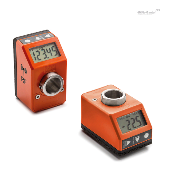
DD51-E - DD51-E-RF Electronic digital position indicator 2. Description The DD51-E position indicators, with battery power supply, can be used, mounted on pass-through shafts, to provide the reading of the absolute or relative positioning of a machine component. Caratteristiche Meccaniche - Elettriche Power supply Lithium battery CR2450 3.0 V... -
Page 7: Version - Dd51-E-Rf
Elesa wireless network is made by the following components: - One control unit UC-RF - Max 36 device as DD51-E-RF , DD52R-E-RF or MPI-R10-RF The UC-RF exchanges information with the DD51-E-RF via radio frequency and makes it possible to set the target position and check the current position of each indicator. -
Page 8: Display
DD51-E - DD51-E-RF Electronic digital position indicator 4. Display 1. Relative mode indicator 2. Low battery level indicator 3. Connection indicator (only for DD51-E-RF) 4. Unit of measure: mm, inch 5. Unit of measure: degrees 6. Target position indications 5. Key functions Models all rights reserved in accordance with the law. - Page 9 DD51-E - DD51-E-RF Electronic digital position indicator Key Or Key Operating Programming Combination Mode Mode Keeping the key pressed down for 3s activate programming mode. When in target mode, it reacts to a short press according to the setting of item _ _ _ _ 0 of the main menu (chap.
- Page 10 DD51-E - DD51-E-RF Electronic digital position indicator Select the measure mode: : absolute measure mode : relative measure mode It is possible to choose one of the following op- tions (see item _ _ O _ _ Digit increase of the menu - chap.8.3):...
-
Page 11: Switching On/Off The Device
DD51-E - DD51-E-RF Electronic digital position indicator Programmable for one of the following functions (see menu item 0 _ _ _ _ 0 – chap.8.3): [DEFAULT]: P_OrG shows and allows you to set the OriGin parameter. : shows and P_StP allows you to set the parameters. -
Page 12: Switching Off The Device (For Storage Only)12
DD51-E - DD51-E-RF Electronic digital position indicator 6.2 Switching off the device (for storage only) To switch the system off: - select the rESEt item from the main menu (see chap.8.3) - using the key , scroll through the items to select OFF . -
Page 13: Resolution
DD51-E - DD51-E-RF Electronic digital position indicator For greater flexibility of use, the DD51-E permits storage of up to 10 different offset values. To program the offset values see the OFFS parameter in chap. 8.2 However, during installation and for other specific applications, it is useful to be able to reset the internal reference value in another position. -
Page 14: Unit Of Measure Selection
DD51-E - DD51-E-RF Electronic digital position indicator absolute measure mode, symbol appears. It is possible to change the function of 0 _ _ _ _ the key by choosing one of the options available in the menu item _ _ 0 _ _... -
Page 15: Direct Programming Of Origin, Offset And Step Parameters
DD51-E - DD51-E-RF Electronic digital position indicator the origin value and an offset value (see chap. 7.1). By pressing the key combination the screen will show the last offset value used (e.g OFS 0 ). It is possible to select the desired offset value by pressing the... -
Page 16: Targets
For programming the parameters listed above see parameter 0 _ _ _ 0 of chap. 8.3. 7.7 Targets The DD51-E allows you to set up to 32 target positions allowing you to store any relevant and frequently used settings. 7.7.1 Programming the targets To program the targets: - select tArGE in the main menu (see chap. -
Page 17: Disabling The Target
DD51-E - DD51-E-RF Electronic digital position indicator the target position indicators. It is possible to set an acceptable tolerance value for the targets through the PtOLL parameter so that the target position is considered to have been reached when the difference between the set target and the current position is less than PtOLL in absolute value. -
Page 18: Version - Dd51-E-Rf
UC-RF manual) it is necessary to take into consideration that the Net CHs are out of phase by 3 channels. In practice, a DD51-E-RF set with Net CH = 1 will communicate with UC-RF on CH = 4 and so on for the following channels. -
Page 19: Targets
DD51-E - DD51-E-RF Electronic digital position indicator 7.8.2 Targets Using the DD51-E-RF , the target positions can be sent from the PLC to the indicators via the UC-RF control unit. When a target is transmitted, it behaves in the same way described in chap. -
Page 20: Programmable Parameters (In Alphabetical Order)
DD51-E - DD51-E-RF Electronic digital position indicator It is not possible to cancel the insertion of a WARNING: parameter value but only to confirm the displayed one. If you do not want to change the value already stored, it is... - Page 21 DD51-E - DD51-E-RF Electronic digital position indicator Parameter Description Available options Default Reference The settable values depend value on the resolution set as follows: Res = 1 : -19999 ÷ 99999 Res = 0.1 : -1999.9 ÷ 9999.9 Res = 0.01: -199.99 ÷...
- Page 22 DD51-E - DD51-E-RF Electronic digital position indicator Parameter Description Available options Default The programmable Conversion StEP 001.00 values depend on the coefficient selected unit of measure: between the number mm: 0.01 ÷ 999.99 of shaft inch : 0.001 ÷ 99.999 rotations gradi: 0.01 ÷...
-
Page 23: Main Menu Tree
DD51-E - DD51-E-RF Electronic digital position indicator 8.3 Main menu tree -19999 ÷ 99999 -19999 ÷ 99999 OFS 0 OFFS -19999 ÷ 99999 OFS 9 StEP mm: 0.01 ÷ 999.99 inch: 0.001 ÷ 99.999 gradi: 0.01 ÷ 999.99 Inch 0.01 0.01... - Page 24 DD51-E - DD51-E-RF Electronic digital position indicator 0° diSP 180° SPEEd 1000 nEt id rAdio ch 01 nEt ch ch 36 0.01 ÷ 9.99 PtoLL Inch 0.001 ÷ 0.393 degrees 0.01÷9.99 See chap. 8.4 tArGE 0 _ _ _ _...
-
Page 25: Target Menu Tree
DD51-E - DD51-E-RF Electronic digital position indicator Target menu tree StoP_t -19999 ÷ 99999 PtG 01 PrOG_t -19999 ÷ 99999 PtG 32 LtG 01 LOAd_t LtG 32 The values must be divided by the number of decimal places of the resolution set. -
Page 26: Device Version
DD51-E - DD51-E-RF Electronic digital position indicator 8.5.3 Device version The device version code is displayed as the last item of the main menu, with the r as the first character. By pressing the key several times, other data are displayed which, if support is required, must be noted and provided to Elesa. -
Page 27: Display Messages And Troubleshooting
DD51-E - DD51-E-RF Electronic digital position indicator 10. Display messages and troubleshoting Message on Description Action the display In operational mode, the device continues to correctly measure the position of the shaft. If the measured value is within the capacity of the display, it will be shown correctly. - Page 28 DD51-E - DD51-E-RF Electronic digital position indicator EU DECLARATION OF CONFORMITY (DoC) COMPANY NAME: Elesa S.p.a. POSTAL ADDRESS: Via Pompei 29 POSTCODE AND CITY: 20900 Monza TELEPHONE NUMBER: +39 039 28111 E-MAIL ADDRESS: info@elesa.com Declare that the DoC is issued under our sole responsibility and...
- Page 29 DD51-E - DD51-E-RF Electronic digital position indicator EU DECLARATION OF CONFORMITY (DoC) COMPANY NAME: Elesa S.p.a. POSTAL ADDRESS: Via Pompei 29 POSTCODE AND CITY: 20900 Monza TELEPHONE NUMBER: +39 039 28111 E-MAIL ADDRESS: info@elesa.com Declare that the DoC is issued under our sole responsibility and...
- Page 30 The Company Elesa S.p.A. can neither be held legally responsible nor liable for lacking or incorrect information and the ensuing consequences. The Company Elesa S.p.A. reserves the right to alter or improve the or parts of them and/ electronic position indicators or the enclosed brochures without prior notice ELESA S.p.A.
Need help?
Do you have a question about the DD51-E and is the answer not in the manual?
Questions and answers