Elesa DD51-E Operating Instructions Manual
Electronic digital position indicators
Hide thumbs
Also See for DD51-E:
- Instructions for use manual (31 pages) ,
- Operating instructions manual (30 pages) ,
- Operating instruction (26 pages)

Related Manuals for Elesa DD51-E


Summary of Contents for Elesa DD51-E
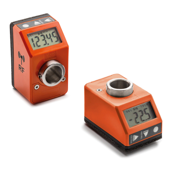
- Page 1 OPERATING INSTRUCTIONS Electronic digital position indicators DD51-E (GN 9054)* DD51-E-RF *(Product series valid only for Germany)
-
Page 2: Table Of Contents
DD51-E - DD51-E-RF Electronic digital position indicators Contents 1. Safety Instructions 1.1 Product release information 2. Description 2.1 Version - DD51-E-RF 3. Installation 4. Display 5. Key functions 6. Switching on/off the device 6.1 Switching on the device 6.2 Switching off the device (for storage only)11 7. - Page 3 DD51-E - DD51-E-RF Electronic digital position indicators 7.9. Version - DD51-E-RF 7.9.1 Programming the Net ID and Net CH parameters 7.9.2 Targets 8. Programming mode 8.1 Input of numeric parameters 8.2 Programmable parameters (in alphabetical order) 8.3 Main menu tree 8.4 Target menu tree...
-
Page 4: Safety Instructions
To comply with FCC (for DD51-E-RF) exposure compliance requirements, the antenna used for this transmitter not be co-located or operating in conjunction with any other antenna or transmitter. -
Page 5: Product Release Information
In case of specific need, it is recommended to ask the Elesa service staff for assistance. Elesa reserves the right, without further communication, to make improvements, additions, corrections to the menu items, that do not modify or affect the described functionality of the product but are necessary for the continuous improvement to which these products are subjected. -
Page 6: Description
> 20 ° C and <30°C and default setup. Furthermore, this value refers to the condition of the device when it leaves the Elesa factory. Long storage times must always be considered for the estimation of the battery life when the device becomes operational. -
Page 7: Version - Dd51-E-Rf
Elesa wireless network is made by the following components: - One control unit UC-RF - Max 36 device as DD51-E-RF , DD52R-E-RF or MPI-R10-RF The UC-RF exchanges information with the DD51-E-RF via radio frequency and makes it possible to set the target position and check the current position of each indicator. -
Page 8: Display
DD51-E - DD51-E-RF Electronic digital position indicators 4. Display 1. Relative mode indicator 2. Low battery level indicator 3. Connection indicator (only for DD51-E-RF) 4. Unit of measure: mm, inch 5. Unit of measure: degrees 6. Target position indications 5. Key functions Models all rights reserved in accordance with the law. - Page 9 DD51-E - DD51-E-RF Electronic digital position indicators Key Or Key Operating Programming Combination Mode Mode Keeping the key pressed down for 3s activate programming mode. When in target mode, it reacts to a short press according to the setting of item _ _ _ _ 0 of the main menu (chap.
- Page 10 DD51-E - DD51-E-RF Electronic digital position indicators Select the measure mode: ABS : absolute measure mode REL : relative measure mode It is possible to choose one of the following options (see Digit increase item _ _ 0 _ _ of the menu - chap.8.3):...
-
Page 11: Switching On/Off The Device
DD51-E - DD51-E-RF Electronic digital position indicators In relative measure mode, resets the measure. In absolute measure mode it is programmable for one of the following functions (see menu item _0 _ 0 – chap.8.3): L_OFS [DEFAULT]: select one of the offsets (see chap.7.6 and 7.7). -
Page 12: Operating Mode
For greater flexibility of use, the DD51-E permits storage of up to 10 different offset values. To program the offset values see the OFFS parameter in chap. 8.2. -
Page 13: Resolution
DD51-E - DD51-E-RF Electronic digital position indicators 7.2 Resolution The device manages different measure display resolution values for each of the three units of measure managed (mm, inch and degrees). The same display resolution set is used to set different parameters such as Origin, offsets and targets. -
Page 14: Unit Of Measure Selection
DD51-E - DD51-E-RF Electronic digital position indicators Press the key to select the required unit of measure. The available options are millimetres, inches and degrees. The selected measure mode is indicated on the display by the symbols: - mm : millimeters... -
Page 15: Direct Programming Of Origin, Offset And Step Parameters
DD51-E - DD51-E-RF Electronic digital position indicators Using this key combination it is possible to reset the measure references of the device by loading the origin value and an offset value (see chap. 7.1). By pressing the key combination the screen will show the last offset value used (e.g OFS 0 ). -
Page 16: Targets
OFF : the key combination is disabled. 7.8 Targets The DD51-E allows you to set up to 32 target positions allowing you to store any relevant and frequently used settings. 7.8.1 Programming the targets To program the targets: - select tArGE in the main menu (see chap. 8.3) - select PrOGt (see chap. -
Page 17: Disabling The Target
DD51-E - DD51-E-RF Electronic digital position indicators the target position indicators. It is possible to set an acceptable tolerance value for the targets through the PtOLL parameter so that the target position is considered to have been reached when the difference between the set target and the current position is less than PtOLL in absolute value. -
Page 18: Version - Dd51-E-Rf
UC-RF manual) it is necessary to take into consideration that the Net CHs are out of phase by 3 channels. In practice, a DD51-E-RF set with Net CH = 1 will communicate with UC-RF on CH = 4 and so on for the following channels. -
Page 19: Targets
Electronic digital position indicators 7.9.2 Targets Using the DD51-E-RF , the target positions can be sent from the PLC to the indicators via the UC-RF control unit. When a target is transmitted, it behaves in the same way described in chap. -
Page 20: Programmable Parameters (In Alphabetical Order)
DD51-E - DD51-E-RF Electronic digital position indicators do not want to change the value already stored, it is obviously possible to set it to the same value as before and check that the word CHAnGd . does not appear. Or, by waiting 30s, the device will exit programming mode without saving the changes. - Page 21 DD51-E - DD51-E-RF Electronic digital position indicators Parameter Description Available options Default Offset It is possible to store up to OFFS values 10 offset value: OFS 0 ... OFS 9 The settable values depend on the resolution set as follows: Res = 1 : -19999 ÷...
- Page 22 DD51-E - DD51-E-RF Electronic digital position indicators Parameter Description Available options Default Maximum 300 ; 600 ; 1000 SPEEd permitted shaft rotation speed The programmable Conversion StEP 001.00 values depend on the coefficient selected unit of measure: between the number mm: 0.01 ÷...
-
Page 23: Main Menu Tree
DD51-E - DD51-E-RF Electronic digital position indicators Parameter Description Available options Default Target It is possible to store up to tArGe 10 offset values: TG 01, ..., positions TG 32. The settable values depend on the resolution set as follows: Res = 1 : -19999 ÷... - Page 24 DD51-E - DD51-E-RF Electronic digital position indicators 0° diSP 180° SPEEd 1000 nEt id rAdio ch 01 nEt ch ch 36 0.01 ÷ 9.99 PtoLL inch 0.001 ÷ 0.393 degrees 0.01÷9.99 See chap. 8.4 tArGE 0 _ _ _ _...
-
Page 25: Target Menu Tree
DD51-E - DD51-E-RF Electronic digital position indicators Target menu tree Target menu tree StoP_t -19999 ÷ 99999 PtG 01 PrOG_t -19999 ÷ 99999 PtG 32 LtG 01 LOAd_t LtG 32 The values must be divided by the number of decimal places of the resolution set. -
Page 26: Device Version
By pressing the key several times, other data are displayed which, if support is required, must be noted and provided to Elesa. WARNING: A variation of the last two digits in the revision code has no impact on the device’s features and performance. -
Page 27: Display Messages And Troubleshooting
DD51-E - DD51-E-RF Electronic digital position indicators 10. Display messages and troubleshoting Message on Description Action the display In operational mode, the device continues to correctly measure the position of the shaft. If the measured value is within the capacity of the display, it will be shown correctly. - Page 28 DD51-E - DD51-E-RF Electronic digital position indicators EU DECLARATION OF CONFORMITY (DoC) COMPANY NAME: Elesa S.p.a. POSTAL ADDRESS: Via Pompei 29 POSTCODE AND CITY: 20900 Monza TELEPHONE NUMBER: +39 039 28111 E-MAIL ADDRESS: info@elesa.com Declare that the DoC is issued under our sole responsibility and...
- Page 29 DD51-E - DD51-E-RF Electronic digital position indicators EU DECLARATION OF CONFORMITY (DoC) COMPANY NAME: Elesa S.p.a. POSTAL ADDRESS: Via Pompei 29 POSTCODE AND CITY: 20900 Monza TELEPHONE NUMBER: +39 039 28111 E-MAIL ADDRESS: info@elesa.com Declare that the DoC is issued under our sole responsibility and...
- Page 30 The Company Elesa S.p.A. can neither be held legally responsible nor liable for lacking or incorrect information and the ensuing consequences. The Company Elesa S.p.A. reserves the right to alter or improve the or parts of them and/ electronic position indicators or the enclosed brochures without prior notice ELESA S.p.A.
Need help?
Do you have a question about the DD51-E and is the answer not in the manual?
Questions and answers