Advertisement
®
XSEDE
Height Adjust
Xsede Height Adjust
Freestanding T-Leg Base
Tools Required
Hardware
•
4—Round Head Socket 5/16-18 X 5/8"
3/16" Hex Drive
8—Flathead Socket 5/16-18 X 1"
•
#2 Phillips Drive
4– Flathead Phillips 1/4-20 X 5/8"
•
Drill
8-Clear Bumpers 1/2" Round X 1/8"
2-Clear Bumpers 1/2" Square X 1/4"
8-Panhead Phillips #8X3/4" Wood Screw
4-Flathead Phillips #10-2 3/8" Wood Screw
4– Panhead Phillips #8 X 5/8" Wood Screws
2-Cable ties.
1— Power Supply Bracket
Installation
1.
Assemble Feet to the Columns using supplied Socket Round
5/16-18 X 5/8" screws. Tighten Screws Firmly. See Figure B.
IMPORTANT: Make sure the correct screws are used. Using
longer screws may destroy the internal parts of the column.
2.
Loosen the set screw and set the Crossbar length based on
top size as seen in Figure C below. Attach the crossbars on
the long side of the bases using supplied Socket Flat Head
5/16-18 X 1" screws. See Figure C.
IMPORTANT: Make sure the correct screws are used. Using
longer screws may destroy the internal parts of the column.
Figure C– Attach Cossbar
Do not use middle hole of cross bar
Part 3049377,B
Proper product installation, in accordance with these instructions, is the responsibility of the installing agent.
If you have any questions concerning these instructions, please call Kimball Customer Care.
Assembly Instructions
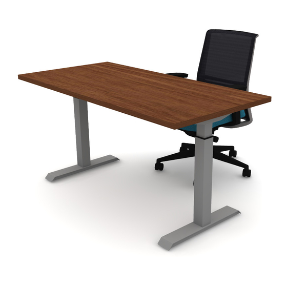
Figure A
Sidebar
Assembled Product
Column
Foot
Figure B– Attach Feet
1
Crossbar
Top
48"
54"
60"
66"
72"
Advertisement
Table of Contents

Related Manuals for Kimball XSEDE


Summary of Contents for Kimball XSEDE
- Page 1 66” 72” Do not use middle hole of cross bar Proper product installation, in accordance with these instructions, is the responsibility of the installing agent. If you have any questions concerning these instructions, please call Kimball Customer Care. Part 3049377,B...
- Page 2 16 7/16” (3 1/2”) (3 1/2”) Figure E– Spacing Bumpers Proper product installation, in accordance with these instructions, is the responsibility of the installing agent. If you have any questions concerning these instructions, please call Kimball Customer Care. Part 3049377,B...
- Page 3 Warning Leaflet Electric User Manual Warning leaflet and user manual should be Proper product installation, in accordance with these instructions, is the responsibility of the installing agent. If you have any questions concerning these instructions, please call Kimball Customer Care. Part 3049377,B...
Need help?
Do you have a question about the XSEDE and is the answer not in the manual?
Questions and answers