
Related Manuals for Chattanooga Group Intelect TRANSPORT Vectra Genisys 2782


Summary of Contents for Chattanooga Group Intelect TRANSPORT Vectra Genisys 2782
- Page 1 Moving Rehabilitation Forward™ System Models: 2782 - Serial numbers 1000 and above 2759 - Serial numbers 1000 and above ISO 13485 CERTIFIED...
-
Page 2: Table Of Contents
Intelect TranSport ® /Vectra Genisys ® Ultrasound Therapy Systems TABLE OF CONTENTS FOREWORD ........1 6.6 Control Board . -
Page 3: Foreword
©2008 Encore Medical, L.P. and its affiliates, Austin, Texas, USA. Any use of editorial, pictorial, or layout composition of this publication without express written consent from Chattanooga Group of Encore Medical, L.P. is strictly prohibited. This publication was written, illustrated, and prepared for print by Chattanooga Group of Encore Medical, L.P. -
Page 4: 1- Safety Precautions
1 SAFETY PRECAUTIONS Intelect TranSport ® /Vectra Genisys ® Ultrasound Therapy Systems PRECAUTIONARY INSTRUCTIONS 1.1 PRECAUTIONARY SYMBOL DEFINITIONS The precautionary instructions found in this manual Read, understand, and follow all safety precautions are indicated by specific symbols. Understand these found in this manual. Below are general safety symbols and their definitions before operating or precautions that must be read and understood servicing this equipment. - Page 5 1 SAFETY PRECAUTIONS Intelect TranSport ® /Vectra Genisys ® Ultrasound Therapy Systems 1.2 SAFETY PRECAUTIONS CONTINUED • Do not apply the Ultrasound Applicator to the patient during the Head Warming period. Applicator must remain in Applicator Hook during the Head Warming period. •...
-
Page 6: 2- Theory Of Operation
Ultrasound Board from the Applicator up to the Control Board. By storing the calibration data in the Applicator there is no calibration necessary for the Ultrasound Board. Calibrated Chattanooga Group Ultrasound Applicators, designed for the Intelect Transport/Vectra Genisys Ultrasound Therapy Systems, can be connected and operated on any Intelect Transport/Vectra Genisys Therapy System to provide accurate coupling and output. -
Page 7: 3- Nomenclature
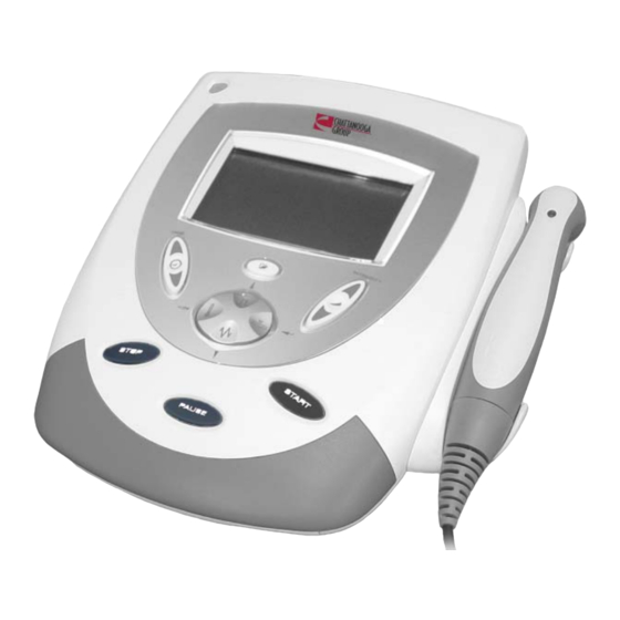
3 NOMENCLATURE Intelect TranSport ® /Vectra Genisys ® Ultrasound Therapy Systems 3.1 INTELECT TRANSPORT/VECTRA components of the Intelect Transport/Vectra Genisys GENISYS ULTRASOUND THERAPY Ultrasound Therapy Systems. SYSTEMS Know the components and their functions before The nomenclature graphics below, Figure 3.1, performing any operation on or service to the indicates the general locations of the exterior Intelect Transport/Vectra Genisys Ultrasound Therapy... -
Page 8: Hardware And Software
3 NOMENCLATURE Intelect TranSport ® /Vectra Genisys ® Ultrasound Therapy Systems 3.2 HARDWARE AND SOFTWARE SYMBOL DEFINITIONS The symbols below are found on the system as Ultrasound Therapy Systems. well as within the software. These symbols are Know the symbols and their definitions before defined for the purpose of recognition and performing any operation of or service to the functionality when operating or performing... - Page 9 3 NOMENCLATURE Intelect TranSport ® /Vectra Genisys ® Ultrasound Therapy Systems 3.2 HARDWARE AND SOFTWARE SYMBOL DEFINITIONS CONTINUED Ultrasound Applicator Connection This port serves as the connection point between the unit and the Ultrasound Applicator. START Select Start to begin a treatment session. Accept and Return Select to accept menu selection and to return to the home screen INTENSITY...
-
Page 10: 4- Specifications
4 SPECIFICATIONS Intelect TranSport ® /Vectra Genisys ® Ultrasound Therapy Systems INTELECT TRANSPORT/VECTRA GENISYS ULTRASOUND THERAPY SYSTEMS Figure 4.1 below provides physical details of the Refer to this section when performing Intelect Transport/Vectra Genisys Ultrasound Therapy troubleshooting, replacement, and repair of the Systems. -
Page 11: Intelect Transport/Vectra Genisys Ultrasound Therapy Systems Specifications
4 SPECIFICATIONS Intelect TranSport ® /Vectra Genisys ® Ultrasound Therapy Systems 4.2 INTELECT TRANSPORT/VECTRA GENISYS ULTRASOUND THERAPY SYSTEMS ULTRASOUND SPECIFICATIONS This section provides the necessary ultrasound specifications to aid in troubleshooting. Refer to these specifications as necessary when troubleshooting the ultrasound PC Board and Applicators. A. -
Page 12: 5- Troubleshooting
No component level troubleshooting Intelect Transport/Vectra Genisys Ultrasound information is or will be provided by Therapy Systems. Once a particular error Chattanooga Group for field troubleshooting of message is defined, the information will also list board components. probable causes and possible remedies. Once B. - Page 13 5 TROUBLESHOOTING Intelect TranSport ® /Vectra Genisys ® Ultrasound Therapy Systems 5.1 INTELECT TRANSPORT/VECTRA GENISYS ULTRASOUND THERAPY SYSTEMS ERROR MESSAGES CONTINUED ERROR ERROR DEFINITION PROBABLE CAUSES POSSIBLE REMEDY CODE TYPE USER CORRECTABLE WARNING MESSAGES CRIT_ERR_US_BOARD Some type of critical Ultrasound Board Ultrasound Board to Control Board Connecting 1.
-
Page 14: Intelect Transport/Vectra Genisys Ultrasound Therapy Systems Diagnostics
Power Meter 2. Due to the complex nature of the technology Recipe(s) for Degassed Water utilized by Chattanooga Group, the 1) Boil distilled water for 30 minutes. Place recommended troubleshooting techniques water in a canning jar, and cover. Allow to are to determine “Bad Board”... -
Page 15: Electrical Safety
5 TROUBLESHOOTING Intelect TranSport ® /Vectra Genisys ® Ultrasound Therapy Systems Listed by Intertek Testing Services NA Inc. 5.3 ELECTRICAL SAFETY Conforms to UL Standard 60601-1 The Intelect Transport/Vectra Genisys Ultrasound Certified to CAN/CSA Standard C22.2 No. Therapy Systems has been tested to IEC/EN 601.1-M90 w/A2 60601-1, Standard for Safety for Medical 9700675... -
Page 16: Visual Inspection
5 TROUBLESHOOTING Intelect TranSport ® /Vectra Genisys ® Ultrasound Therapy Systems 5.5 VISUAL INSPECTION 4. Fan not blowing outward, unit failed test Visually inspect the Intelect Transport/Vectra a) Fan blowing inward. Genisys Ultrasound Therapy Systems. A visual Fan wired wrong. Rewire or replace Fan. inspection can, to an experienced technician, 5. -
Page 17: Ultrasound Board Test
5 TROUBLESHOOTING Intelect TranSport ® /Vectra Genisys ® Ultrasound Therapy Systems 5.7 ULTRASOUND BOARD TEST NOTE: This test is designed to eliminate or verify a ULTRASOUND problem with the Ultrasound Board. BOARD A. Test 1. Separate top from bottom. Refer to 6.1, part C. -
Page 18: Power Supply Test
5 TROUBLESHOOTING Intelect TranSport ® /Vectra Genisys ® Ultrasound Therapy Systems 5.8 POWER SUPPLY TEST A. Test 1. Separate top from bottom. Refer to 6.1, part C. 2. Disconnect the Power Supply Harness from the Control Board. Lay the unit open. 3. -
Page 19: Ultrasound Tests
Ohmic Instruments UPM DT 10 or UPM DT 100 Ultrasound Power Meter • Known good Ultrasound Applicator NOTE: Use any Ultrasound Applicator supplied with a Chattanooga Group unit for this test. B. Ultrasound Applicator Identification FIGURE 5.4 Test Procedures 1. Without Ultrasound Applicator installed, turn unit on. -
Page 20: Ultrasound Applicator Ouptut Test
5 TROUBLESHOOTING Intelect TranSport ® /Vectra Genisys ® Ultrasound Therapy Systems 5.10 ULTRASOUND APPLICATOR OUTPUT TEST Perform this test using all available Ultrasound NOTE: Applicators used with the system being tested. The position of the Applicator over the stainless steel cone is critical to the test results. NOTE: The Applicator must be level and centered. - Page 21 5 TROUBLESHOOTING Intelect TranSport ® /Vectra Genisys ® Ultrasound Therapy Systems 5.10 ULTRASOUND APPLICATOR OUTPUT TEST (CONTINUED) C. Timer Control/End of Treatment Test NOTE: Prior to testing, verify that Head Warming is off. Head Warming emitts ultrasound and the intensity will not reset to zero if Head Warming is on.
-
Page 22: Ultrasound Duty Cycle Test
5 TROUBLESHOOTING Intelect TranSport ® /Vectra Genisys ® Ultrasound Therapy Systems 5.11 ULTRASOUND DUTY CYCLE TEST e) Check Ultrasound Board. Perform this test using all Ultrasound Applicators f) Check Control Board. used with the system being tested. A. Ultrasound Duty Cycle Test Procedures 1. -
Page 23: 6- Removal & Replacement
6 REMOVAL & REPLACEMENT Intelect TranSport ® /Vectra Genisys ® Ultrasound Therapy Systems 6.1 SEPARATING TOP FROM BOTTOM REMOVE MAINS REMOVE POWER CORD PLYNTH Unplug the unit from the power source and/or remove battery before attempting any removal or replacement procedures to prevent electrical shock. A. -
Page 24: Fan
6 REMOVAL & REPLACEMENT Intelect TranSport ® /Vectra Genisys ® Ultrasound Therapy Systems 6.2 FAN REMOVE SCREWS BAFFLE Unplug the unit from the power source and/or remove battery before attempting any removal or replacement procedures to prevent electrical shock. A. Part Numbers ........27158 B. -
Page 25: Power Supply
6 REMOVAL & REPLACEMENT Intelect TranSport ® /Vectra Genisys ® Ultrasound Therapy Systems 6.3 POWER SUPPLY ROUTE HARNESS AS SHOWN Unplug the unit from the power source and/or remove battery before attempting any removal or replacement procedures to prevent electrical shock. - Page 26 6 REMOVAL & REPLACEMENT Intelect TranSport ® /Vectra Genisys ® Ultrasound Therapy Systems 6.3 POWER SUPPLY (CONTINUED) 6. Remove Power Supply from system. POWER SUPPLY 7. Carefully remove the copper tape securing the ALIGNMENT PINS shield to the Power Supply. Remove from the inside of the Power Supply and retain the Shield for installation of the replacement.
-
Page 27: Ultrasound Board
6 REMOVAL & REPLACEMENT Intelect TranSport ® /Vectra Genisys ® Ultrasound Therapy Systems 6.4 ULTRASOUND BOARD SCREW SCREW A. Part Number ............27269 Unplug the unit from the power source and/or remove battery before attempting any removal or replacement procedures to prevent electrical shock. -
Page 28: Lcd Display
6 REMOVAL & REPLACEMENT Intelect TranSport ® /Vectra Genisys ® Ultrasound Therapy Systems 6.5 LCD DISPLAY 2 SCREWS EACH END RELEASE RETAINING BRACKET TABS Unplug the unit from the power source and/or remove battery before attempting any removal or replacement procedures to prevent electrical shock. -
Page 29: Control Board
6 REMOVAL & REPLACEMENT Intelect TranSport ® /Vectra Genisys ® Ultrasound Therapy Systems 6.6 CONTROL BOARD RETAINING SCREWS Unplug the unit from the power source and/or remove battery before attempting any removal or replacement procedures to prevent electrical shock. A. Part Number ............27268 B. -
Page 30: Applicator Sound Head
6 REMOVAL & REPLACEMENT Intelect TranSport ® /Vectra Genisys ® Ultrasound Therapy Systems 6.8 APPLICATOR SOUND HEAD A. Part Numbers (Applicators) Intelect Applicators 1 cm² ................27381 2 cm² ................27382 5 cm² ................27383 10 cm² ................27384 Genisys Applicators 1 cm²... -
Page 31: Applicator Probe Spring Holder
6 REMOVAL & REPLACEMENT Intelect TranSport ® /Vectra Genisys ® Ultrasound Therapy Systems 6.9 APPLICATOR PROBE SPRING HOLDER A. Part Number ............27040 B. Tools and Equipment Required BRASS • #1 Phillips Screwdriver PROBE SPRING C. Probe Spring Holder Removal and Replacement 1. -
Page 32: Applicator Pc Board
6 REMOVAL & REPLACEMENT Intelect TranSport ® /Vectra Genisys ® Ultrasound Therapy Systems 6.10 APPLICATOR PC BOARD A. Part Numbers 1 cm² ................27600 2 cm² ................27071 5 cm² ................27073 10 cm² ................27075 B. Tools and Equipment Required •... -
Page 33: Applicator Cable
6 REMOVAL & REPLACEMENT Intelect TranSport ® /Vectra Genisys ® Ultrasound Therapy Systems 6.11 APPLICATOR CABLE A. Part Numbers Gray Applicator Cable ........27351 Blue Applicator Cable ........27106 B. Tools and Equipment Required • #1 Phillips Screwdriver C. PC Board Removal and Replacement 1. -
Page 34: 7- Ultrasound Applicator Calibration
7 ULTRASOUND APPLICATOR CALIBRATION Intelect TranSport ® /Vectra Genisys ® Ultrasound Therapy Systems 7.1 GENERAL PROCEDURES A. Tools and Equipment Required • All Ultrasound Applicators for the unit being serviced • Ohmic Instruments UPM DT 10 or UPM DT 100 ultrasound power meter, set to "Watts" •... -
Page 35: 8- Parts
8 PARTS Intelect TranSport ® /Vectra Genisys ® Ultrasound Therapy Systems 8.1 TOP ASSEMBLY ITEM PART DESCRIPTION NUMBER NUMBER REQ'D 27399 TOP MOULDING ASSEMBLY (GREY) 27244 TOP MOULDING ASSEMBLY (BLUE) SEE CONTROL CONTROL ASSEMBLY BOARD ASSY DRAWING 27368 KEYMAT (GREY) 27255 KEYMAT (BLUE) PART OF KEYMAT... -
Page 36: Ultrasound Assembly
8 PARTS Intelect TranSport ® /Vectra Genisys ® Ultrasound Therapy Systems 8.2 ULTRASOUND ASSEMBLY NOTE: INSERT #3 INTO PCB #2 FIRST, THEN INTO #1 NOTE: INSERT #3 INTO PCB #2 FIRST, THEN INTO #1 ITEM PART DESCRIPTION NUMBER NUMBER REQ'D SEE TOP TOP ASSEMBLY ASSY... -
Page 37: Control Board Assembly
8 PARTS Intelect TranSport ® /Vectra Genisys ® Ultrasound Therapy Systems 8.3 CONTROL BOARD ASSEMBLY NOTE: INSERT #4 THROUGH NOTE: INSERT #4 THROUGH TOP ROW OF SOCKET TOP ROW OF SOCKET CONNECTOR OF #1 CONNECTOR OF #1 ITEM PART DESCRIPTION NUMBER NUMBER REQ'D... -
Page 38: Base Assembly
8 PARTS Intelect TranSport ® /Vectra Genisys ® Ultrasound Therapy Systems 8.4 BASE ASSEMBLY NOTE TUCK FERRITE UNDER POWER 10 10 SUPPLY DETAIL A PLACE INSULATED SIDE OF SHIELD NEXT TO POWER SUPPLY TUCK FERRITE UNDER POWER SUPPLY AND INTO CORNER SEE DETAIL A OTE: COPPER TAPE... - Page 39 8 PARTS Intelect TranSport ® /Vectra Genisys ® Ultrasound Therapy Systems 8.4 BASE ASSEMBLY (CONTINUED) ITEM PART DESCRIPTION NUMBER NUMBER REQ'D 27259 CONNECTOR INFILL PANEL 27367 FAN SEAL 27265 POWER SUPPLY 27158 27152 UNIVERSAL SNAP-IN INLET (IEC SOCKET) 27136 M4 X 35MM SCREW PAN HEAD 27142 M3 X 6MM SCREW PAN HEAD 27592...
-
Page 40: Final Assembly
8 PARTS Intelect TranSport ® /Vectra Genisys ® Ultrasound Therapy Systems 8.5 FINAL ASSEMBLY CONNECTOR POWER SUPPLY CONNECTOR LEFT RIGHT BATTERY CONNECTOR (OPTIONAL) ITEM PART DESCRIPTION NUMBER NUMBER REQ'D SEE TOP ASSY TOP ASSEMBLY DRAWING SEE BASE ASSY BASE ASSEMBLY DRAWING... - Page 41 8 PARTS Intelect TranSport ® /Vectra Genisys ® Ultrasound Therapy Systems 8.5 FINAL ASSEMBLY (CONTINUED) ITEM PART DESCRIPTION NUMBER NUMBER REQ'D 27410 BATTER COMPARTMENT COVER ASSEMBLY 27253 PLYNTH 27361 REAR VENT (GREY) 27263 REAR VENT (BLUE) 27363 FOOT LEFT 27365 FOOT RIGHT 27478 BATTERY PACK...
-
Page 42: 9- Schematics
9 SCHEMATICS Intelect TranSport ® /Vectra Genisys ® Ultrasound Therapy Systems 9.1 ULTRASOUND BOARD (1) - PORTS... - Page 43 9 SCHEMATICS Intelect TranSport ® /Vectra Genisys ® Ultrasound Therapy Systems 9.2 ULTRASOUND BOARD (2) - AMPS...
- Page 44 9 SCHEMATICS Intelect TranSport ® /Vectra Genisys ® Ultrasound Therapy Systems 9.3 ULTRASOUND BOARD (3) - POWER SUPPLY...
- Page 45 9 SCHEMATICS Intelect TranSport ® /Vectra Genisys ® Ultrasound Therapy Systems 9.4 CONTROL BOARD (1)
- Page 46 9 SCHEMATICS Intelect TranSport ® /Vectra Genisys ® Ultrasound Therapy Systems 9.5 CONTROL BOARD (2)
-
Page 47: 10- Warranty
10 WARRANTY Intelect TranSport ® /Vectra Genisys ® Ultrasound Therapy Systems Chattanooga Group, a division of Encore Medical L. P., ("Company") warrants that the Intelect Transport/Vectra Genisys Ultrasound Therapy Systems ("Product") is free of defects in material and workmanship. This warranty shall remain in effect for two years (24 months) from the date of original consumer purchase. - Page 48 Moving Rehabilitation Forward™ ISO 13485 CERTIFIED 4717 Adams Road P.O. Box 489 Hixson, TN 37343 1-800-592-7329 1 423-870-2281 1 423-875-5497 FAX *27670* chattgroup.com 27670C © 2008 Encore Medical, L.P.
Need help?
Do you have a question about the Intelect TRANSPORT Vectra Genisys 2782 and is the answer not in the manual?
Questions and answers
How do you electrical safety test this
To perform electrical safety testing on the Chattanooga Group Intelect TRANSPORT Vectra Genisys 2782, follow these steps:
1. Power Requirements Check: Ensure the unit operates within the specified input range of 100-240VAC, 75 VA, 50/60 Hz.
2. Leakage Testing: Conduct all necessary leakage tests according to NFPA 99 (National Fire Protection Association) “Health Care Facility” standards.
3. Dielectric Withstand Test: If the unit fails this test or the leakage test, it may indicate serious internal issues. Do not attempt to repair it yourself; send it to the factory for repair.
4. Visual Inspection:
- Check for any visible signs of damage or abuse.
- Ensure the fan is functioning correctly.
5. Unit Startup and Fan Testing:
- The fan should function only when the ultrasound is being emitted.
- If the fan is not blowing outward, check if it is wired incorrectly and rewire or replace it if necessary.
- If the fan is not operating at all, it may be faulty and require replacement.
Following these steps ensures compliance with safety standards and proper functionality of the unit.
This answer is automatically generated