
Related Manuals for Chattanooga Group OptiFlex 2030


Summary of Contents for Chattanooga Group OptiFlex 2030
- Page 1 ® SERVICE MANUAL Models: 2030 (Serial Numbers- 5000 and above) 2060 (Serial Numbers- 5000 and above) ISO 9001/ISO 13485 CERTIFIED...
-
Page 3: Table Of Contents
©2002 Encore Medical Corporation or its affiliates, Austin, Texas, USA. Any use of editorial, pictorial or layout composition of this publication without express written consent from the Chattanooga Group of Encore Medical, L.P. is strictly prohibited. This publication was written, illustrated and prepared for print by the Chattanooga Group of Encore Medical, L.P. -
Page 5: Forword
It is the sole responsibility for field technicians to stay informed and trained in the latest technology utilized in the OptiFlex CPM Models 2030 and 2060 units by Chattanooga Group from time to time, as significant improvements are incorporated, Service Bulletins will be produced and made available on our web site (www.chattgroup.com) in lieu of reprinting a complete manual prematurely. -
Page 6: 1- Safety Precautions
SAFETY PRECAUTIONS OptiFlex 2030 & 2060 ® Precautionary Symbol Definitions Safety Precautions The precautionary instructions found throughout this Read, understand and follow all safety precautions manual are indicated by specific symbols. found in this manual. Below are general safety Understand these symbols and their definitions before precautions that must be read and understood before operating or servicing this equipment. -
Page 7: Safety Precautions
SAFETY PRECAUTIONS OptiFlex 2030 & 2060 ® Safety Precautions Continued DANGER CAUTION • Explosion hazard if used in the presence of flammable anesthetics. The warning symbol for • OptiFlex has been designed for maximum protection this hazard is prominently displayed on the serial against the exposure of urinary incontinence. -
Page 8: 2- Theory Of Operation
2.1 Overview The OptiFlex 2030 & 2060 CPM products are comprised of two PC Board assemblies housed within the head section of the unit along with the Motor and Gearbox Assembly. These components are linked to a Pendant via a cable connection that provides the operator access for set up and operation of the unit. -
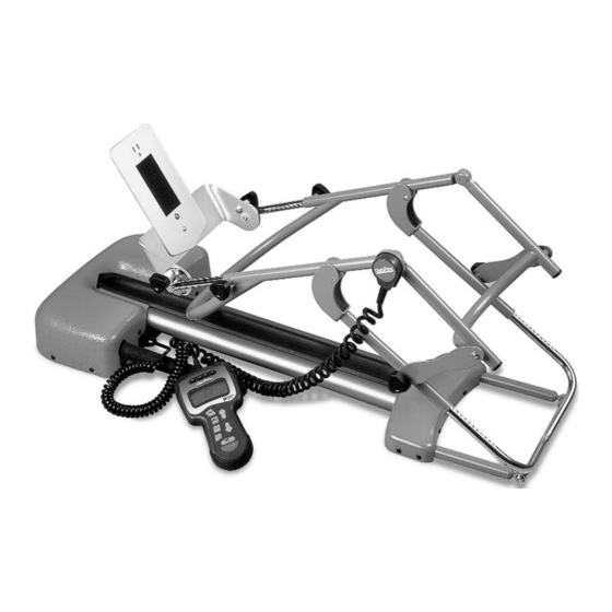
Page 9: 3- Nomenclature
3.1 OptiFlex Familiarization Know the components and their functions before performing The nomenclature graphics below, Figure 3.1, indicate the any operation of or service to the OptiFlex 2030 or 2060 general locations of the major components of the OptiFlex CPM unit. - Page 10 3.2 OptiFlex Pendant Familiarization Know the components and their functions before performing The Pendant nomenclature graphics below, Figure 3.2, any operation of or service to the OptiFlex 2030 or 2060 indicate the location and functions of the OptiFlex CPM CPM unit.
-
Page 11: 4- Specifications
SPECIFICATIONS OptiFlex 2030 & 2060 ® MODEL 2030 Input: 120 VAC~50/60 Hz, 40 Watts Weight: 28 Lbs. (13 kg) Length: 37 in. (94 cm) Operation Knee Flexion ROM Limit: 120° Knee Extension Limit: -10° Hyper Extension Knee Speed Range : 30°/min. -
Page 12: 5- Troubleshooting
OptiFlex 2030 & 2060 ® 5.1 OptiFlex Software Error Messages or will be provided by Chattanooga Group for A. The information provided below is intended to field troubleshooting of board components. aid in troubleshooting Software Error Messages of the OptiFlex Units to “Board Level” only. No B. - Page 13 2 2 . . Due to the complex nature of the technology it will be necessary to obtain the proper size tools for utilized by Chattanooga Group, the recommended removal and replacement of certain components. troubleshooting techniques are to determine “Bad The lubricants and locking componds listed below are Board”...
- Page 14 TROUBLESHOOTING OptiFlex 2030 & 2060 ® 5 5 . . 3 3 V V i i s s u u a a l l I I n n s s p p e e c c t t i i o o n n A A .
- Page 15 TROUBLESHOOTING OptiFlex 2030 & 2060 ® Using the Inclinometer or Protractor measure the B B . . T T e e s s t t angle of the flexion of the unit. Compare to Spec. See Place unit on a level work surface. Figure 5.6.
-
Page 16: 6- Removal & Replacement Procedures
REMOVAL & REPLACEMENT OptiFlex 2030 & 2060 ® 6 6 . . 1 1 C C o o v v e e r r R R e e m m o o v v a a l l & & R R e e p p l l a a c c e e m m e e n n t t N N O O T T E E : : Retain both parts of the push rivets for re-installation. - Page 17 REMOVAL & REPLACEMENT OptiFlex 2030 & 2060 ® 6 6 . . 2 2 M M a a i i n n P P C C B B o o a a r r d d R R e e m m o o v v a a l l & & R R e e p p l l a a c c e e m m e e n n t t N N O O T T E E : : A A .
- Page 18 REMOVAL & REPLACEMENT OptiFlex 2030 & 2060 ® Using the #2 Phillips Screwdriver, remove the two mounting screws securing the Motor PC Board Assembly to the unit. See Figure 6.8. L L O O O O S S E E N N T T H H R R E E E E M M O O T T O O R R M M O O U U N N T T I I N N G G S S C C R R E E W W S S F F I I G G U U R R E E 6 6 .
- Page 19 REMOVAL & REPLACEMENT OptiFlex 2030 & 2060 ® B B . . M M o o t t o o r r C C o o v v e e r r R R e e m m o o v v a a l l Remove the three motor mounting screws using the 9/64”...
- Page 20 REMOVAL & REPLACEMENT OptiFlex 2030 & 2060 ® 7 7 . . 1 1 P P o o t t e e n n t t i i o o m m e e t t e e r r ( ( K K n n e e e e P P o o t t ) ) R R e e m m o o v v a a l l & & R R e e p p l l a a c c e e m m e e n n t t C C .
- Page 21 REMOVAL & REPLACEMENT OptiFlex 2030 & 2060 ® With the 3/32” Allen Wrench loosen the two set screws retaining the potentiometer in position. See P P L L A A C C E E P P R R O O T T R R A A C C T T O O R R A A C C R R O O S S S S T T H H E E S S E E T T W W O O S S U U R R F F A A C C E E S S A A N N D D A A D D J J U U S S T T Figure 7.5.
-
Page 22: 8-Calibration
CALIBRATION OptiFlex 2030 & 2060 ® 8 8 . . 1 1 A A n n n n u u a a l l C C a a l l i i b b r r a a t t i i o o n n P P r r o o c c e e d d u u r r e e s s P P L L A A C C E E P P R R O O T T R R A A C C T T O O R R A A C C R R O O S S S S T T H H E E S S E E The OptiFlex CPM unit should be calibrated annually T T W W O O S S U U R R F F A A C C E E S S A A N N D D A A D D J J U U S S T T... - Page 23 MAINTENANCE / CALIBRATION RECORD OptiFlex 2030 & 2060 ®...
-
Page 24: 9- Replacement Parts
REPLACEMENT PARTS OptiFlex 2030 & 2060 ® With Femur Bar... - Page 25 REPLACEMENT PARTS OptiFlex 2030 & 2060 ® With Femur Bar J6028 BUSHING, NYLON 5/16” OD J1003 COVER, POT J1072 BUSHING, NYLON 3/8” OD J6024 SCREW, POT MOUNT, #6-32 40100 MOTOR, BRUSHLESS J1071 PIN, FOOT ROTATION 40101 GEARBOX J1068 VELCRO LOOP J2003 EXTRUSION J1061...
- Page 26 REPLACEMENT PARTS OptiFlex 2030 & 2060 ® Without Femur Bar...
- Page 27 REPLACEMENT PARTS OptiFlex 2030 & 2060 ® Without Femur Bar J6028 BUSHING, NYLON 5/16” OD J1061 SLEEVE, CARRIAGE PIVOT J1072 BUSHING, NYLON 3/8” OD J6007 SCREW, PIVOT, 1/4”-28 X 5/8” 40100 MOTOR, BRUSHLESS 65991 TUBE PLUG 40101 GEARBOX J6012 KNOB, MALE 1/4”-20 J2003 EXTRUSION 62066...
- Page 28 ISO 9001/ISO 13485 CERTIFIED 4717 Adams Road P.O. Box 489 Hixson, TN 37343 U.S.A. 1-423-870-2281 1-800-592-7329 U.S.A. 1-800-361-6661 CANADA + 1-423-870-2046 OUTSIDE U.S.A. FAX www.chattgroup.com P P a a r r t t N N u u m m b b e e r r : : 2 2 0 0 6 6 9 9 6 6 A A ©...
Need help?
Do you have a question about the OptiFlex 2030 and is the answer not in the manual?
Questions and answers