Table of Contents
Advertisement
Advertisement
Table of Contents
Troubleshooting

Related Manuals for Chattanooga Group TRITON 4749


Summary of Contents for Chattanooga Group TRITON 4749
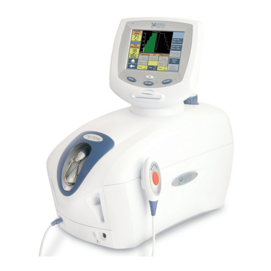
- Page 1 SERVICE MANUAL Traction Unit Applies to Serial numbers 1000 and above International Model- 4749 International with sEMG Model- 4798 Domestic Model- 4739 Domestic with sEMG Model- 4778 Domestic DTS Model- 2841 ISO 13485 Certifi ed © 2006 Encore Medical, L.P.
-
Page 2: Table Of Contents
TABLE OF CONTENTS Triton® Traction Unit FOREWORD ..........1 6.9 TRACTION CORD REMOVAL & REPLACEMENT ....41-46 1... -
Page 3: Foreword
©2006 Encore Medical Corporation or its affiliates, Austin, Texas, USA. Any use of editorial, pictorial, or layout composition of this publication without express written consent from the Chattanooga Group of Encore Medical, L.P. is strictly prohibited. This publication was written, illustrated, and prepared for print by the Chattanooga Group of... -
Page 4: 1 Theory Of Operation
1 THEORY OF OPERATION Triton® Traction Unit 1.1 OVERVIEW The Triton traction unit is comprised of several pieces of proprietary hardware and software causing the unit to function as required allowing administration of traction therapy under the prescription and supervision of a licensed medical practitioner. -
Page 5: 2 Safety Precautions
Chattanooga Group Service Department for help. • The unit should be routinely checked before each use to determine all controls function normally. - Page 6 Chattanooga Group for service. Errors and Warnings move towards the traction head to release the in these categories indicate an internal problem tension on the rope.
- Page 7 DO NOT connect the unit to an electrical by other companies on this (table, unit, device, supply without first verifying that the etc.). Chattanooga Group is not responsible for power supply is the correct voltage. any consequence resulting from using products Incorrect voltage may cause unit damage, manufactured by other companies.
-
Page 8: 3 Nomenclature
3 NOMENCLATURE Triton® Traction Unit 3.1 TRITON UNIT EXTERNAL COMPONENTS The nomenclature graphics below, Figure 3.1, Know the components and their functions before indicate the general locations of the major external performing any operation of or service to the components of the Triton traction unit. Triton traction unit. -
Page 9: Internal Components
3 NOMENCLATURE Triton® Traction Unit 3.2 INTERNAL COMPONENTS The nomenclature graphics below, Figure 3.2, Know the components and their functions before indicate the locations of the major internal performing any operation of or service to the components of the Triton traction unit. Triton traction unit. -
Page 10: 4 Specifications
4 SPECIFICATIONS Triton® Traction Unit 4.1 PHYSICAL SPECIFICATIONS HEIGHT DEPTH WIDTH FIGURE 4.1 Width ....... . . 24 cm (9.5 in) Traction Modes. -
Page 11: 5 Troubleshooting
MMC in the unit is not a software upgrade MMC. WARNING Error upgrading Control Board software. Unknown Contact Dealer or Chattanooga Group for Service. WARNING Error upgrading motor board software. Unknown Contact Dealer or Chattanooga Group for Service. WARNING User pressed START, but has not yet set User has not completed Treatment Set Up. - Page 12 Group for service. Errors and Warnings in these categories indicate an internal problem with the unit that must be tested by Chattanooga Group or a Field Service Technician certified by Chattanooga Group before any further operation or use of the unit. Use of a unit that indicates an Error or Warning in these categories may pose a risk of injury to the patient, user, or may cause extensive internal damage to the unit.
- Page 13 Group for service. Errors and Warnings in these categories indicate an internal problem with the unit that must be tested by Chattanooga Group or a Field Service Technician certified by Chattanooga Group before any further operation or use of the unit. Use of a unit that indicates an Error or Warning in these categories may pose a risk of injury to the patient, user, or may cause extensive internal damage to the unit.
- Page 14 Group for service. Errors and Warnings in these categories indicate an internal problem with the unit that must be tested by Chattanooga Group or a Field Service Technician certified by Chattanooga Group before any further operation or use of the unit. Use of a unit that indicates an Error or Warning in these categories may pose a risk of injury to the patient, user, or may cause extensive internal damage to the unit.
- Page 15 Triton® Traction Unit NOTES...
-
Page 16: Triton Traction Unit Testing
No PCB capacity. component level troubleshooting is recommended nor will information or parts • Allen Wrenches be supplied by Chattanooga Group. Any PC • SAE- 3/32, 5/32, and 9/64 in board component level troubleshooting • Metric- 3 mm performed will be at the sole risk and liability •... -
Page 17: Visual Inspection
5 TROUBLESHOOTING Triton® Traction Unit 5.3 VISUAL INSPECTION 5.5 LEAKAGE TESTS A. General Visually inspect the unit. A visual inspection can, to an experienced Technician, UNIT FAILING DIELECTRIC WITHSTAND AND/OR indicate possible abuse of the unit and LEAKAGE TESTS COULD INDICATE SERIOUS internal problems. -
Page 18: On/Off Switch Test
5 TROUBLESHOOTING Triton® Traction Unit 5.6 ON/OFF SWITCH TEST A. Specification Unit turns Off and On B. Equipment Required None C. On/Off Switch Test Procedure 1. Place unit on level work surface. ON/OFF 2. Plug Power Cord into grounded power source SWITCH with appropriate voltage. -
Page 19: Patient Interrupt Switch Test
5 TROUBLESHOOTING Triton® Traction Unit 5.8 PATIENT INTERRUPT SWITCH TEST A. Specification Unit displays Error 101 or 102 at the respective test. B. Equipment Required None C. Patient Interrupt Switch Test Procedure 1. Place unit on level work surface. Plug Power Cord into grounded power source with appropriate voltage. -
Page 20: Cord Release And Retract Test
5 TROUBLESHOOTING Triton® Traction Unit 5.9 CORD RELEASE AND RETRACT TEST A. Specification Release ....Cord releases with less than 5 lbs tension Retract . -
Page 21: Cord Release Troubleshooting
5 TROUBLESHOOTING Triton® Traction Unit 5.10 CORD RELEASE TROUBLESHOOTING A. Specification Solenoid Supply Voltage ..24 VDC ±5% Solenoid Gear . .Properly engages Driven Gear B. Equipment Required 1. Digital Multimeter 2. #1 Phillips Screwdriver 3. - Page 22 5 TROUBLESHOOTING Triton® Traction Unit 5.10 CORD RELEASE TROUBLESHOOTING (continued) 2. Motor Control Board a. Disconnect Solenoid Harness from J8 on Motor Control Board. See Figure 5.14. b. Make certain unit is connected to an approved power supply outlet and turn unit On with Power Switch.
-
Page 23: Load Cell Test
5 TROUBLESHOOTING Triton® Traction Unit 5.11 LOAD CELL TEST A. Specification Touch Screen Reading ....±10% B. Equipment Required 1. Calibration Fixture with calibrated Load Cell C. -
Page 24: Load Cell Troubleshooting
5 TROUBLESHOOTING Triton® Traction Unit 5.12 LOAD CELL TROUBLESHOOTING A. Specification Voltage to Load Cell ....10 VDC Voltage from Load Cell ....Variable Motor Control Board Voltage (U3) . - Page 25 5 TROUBLESHOOTING Triton® Traction Unit 5.12 LOAD CELL TROUBLESHOOTING (continued) D. Voltage from Load Cell Tests NOTE: It will be necessary to have two people available for the following test. 1. Set Multimeter to read 10 VDC. Make connection with Pin 3 (Blue wire) and Pin 4 (Green wire) from the side of the RED LEAD connector with Multimeter Leads.
-
Page 26: Touch Screen Test
5 TROUBLESHOOTING Triton® Traction Unit 5.13 TOUCH SCREEN TEST A. Specification Contrast Control ..Touch Screen Dims and Brightens Touch Screen ..Displays proper Screen B. -
Page 27: Touch Screen Troubleshooting
5 TROUBLESHOOTING Triton® Traction Unit 5.14 TOUCH SCREEN TROUBLESHOOTING PIN 2 PIN 1 A. Specification Voltage to Touch Screen: J6 Connector ....5 VDC ±5% Display Connector . -
Page 28: Power Supply Troubleshooting
5 TROUBLESHOOTING Triton® Traction Unit 5.15 POWER SUPPLY TROUBLESHOOTING A. Specification Power Supply Input . . 100 V-240 V (50/60 Hz) Power Supply Output ...24 VDC ±5% B. Equipment Required 1. -
Page 29: Semg Tests
5 TROUBLESHOOTING Triton® Traction Unit 5.16 sEMG TESTS This test is to be performed on the Triton Traction ATTENUATOR SCHEMATIC unit only with the sEMG Module properly installed. Perform this test on all Channels with sEMG. 100K 1% A. Test Equipment Required It will be necessary to build an Attenuator 49.9 OHM 1% GREEN... - Page 30 5 TROUBLESHOOTING Triton® Traction Unit 5.16 sEMG TESTS (continued) 3. If icons are present, connect known good sEMG Lead Wire to the Triton Traction unit. See Figure 5.37. FIGURE 5.37 4. Connect the sEMG Lead Wires into the Attenuator. Make certain the sEMG Lead is connected to its respective color on the Attenuator.
- Page 31 5 TROUBLESHOOTING Triton® Traction Unit 5.16 sEMG TESTS (continued) 7. Make certain the Audio Signal Generator is set up per 5.16, part B, steps 1, a) through 1, g). Connect the Audio Signal Generator Test Leads from the Generator SYNC Ports to the Attenuator (make certain test leads are connected red to red and black to black).
-
Page 32: 6 Removal & Replacement
6 REMOVAL & REPLACEMENT Triton® Traction Unit 6.1 SIDE COVER REMOVAL & REPLACEMENT Unplug the unit from the power source before attempting removal or replacement procedures to prevent electrical shock. A. Part Numbers Side Cover (2 Req'd) ....47857 B. -
Page 33: Top And Cord Guide Cover Removal & Replacement
6 REMOVAL & REPLACEMENT Triton® Traction Unit 6.2 TOP AND CORD GUIDE COVER REMOVAL & REPLACEMENT WHEN INSTALLING, RIBBON CABLE BLACK STRIP MUST BE Unplug the unit from the power source before TOWARD THE TOP OF THE MOTOR CONTROL BOARD. attempting removal or replacement procedures to prevent electrical shock. -
Page 34: Rear Cover Removal & Replacement
6 REMOVAL & REPLACEMENT Triton® Traction Unit 6.3 REAR COVER REMOVAL & REPLACEMENT Unplug the unit from the power source before attempting removal or replacement procedures to prevent electrical shock. A. Part Numbers Rear Cover Assembly ....48110 B. -
Page 35: Front Cover Removal & Replacement
6 REMOVAL & REPLACEMENT Triton® Traction Unit 6.4 FRONT COVER REMOVAL & REPLACEMENT PATIENT INTERRUPT Unplug the unit from the power source before SWITCH HARNESS attempting removal or replacement procedures to prevent electrical shock. A. Part Numbers Front Cover ......47858 B. - Page 36 6 REMOVAL & REPLACEMENT Triton® Traction Unit The remaining removal and replacement procedures in this section require that the following be performed after component or assembly replacement to ensure proper alignment and operation of the unit: 1. COMPLETE CALIBRATION OF UNIT 2.
-
Page 37: Motor Control Board Removal & Replacement
6 REMOVAL & REPLACEMENT Triton® Traction Unit 6.5 MOTOR CONTROL BOARD REMOVAL & REPLACEMENT LOAD CELL HARNESS Unplug the unit from the power source before attempting removal or replacement procedures to USB HARNESS prevent electrical shock. A. Part Numbers Motor Control Board ....47803 TOUCH SCREEN B. -
Page 38: Touch Screeen Assembly Removal & Replacement
6 REMOVAL & REPLACEMENT Triton® Traction Unit 6.6 TOUCH SCREEEN ASSEMBLY REMOVAL & REPLACEMENT TOP MOULDING PLATE Unplug the unit from the power source before MOUNTING SCREWS attempting removal or replacement procedures to prevent electrical shock. A. Part Numbers Touch Screen Assembly ....48063 B. - Page 39 6 REMOVAL & REPLACEMENT Triton® Traction Unit 6.6 TOUCH SCREEN ASSEMBLY REMOVAL & REPLACEMENT (continued) Unplug the unit from the power source before attempting removal or replacement procedures to prevent electrical shock. D. Replacing Touch Screen Assembly 1. Place new Touch Screen Assembly into Touch Screen to Cover Assembly Jig.
-
Page 40: Load Cell Assembly Removal & Replacement
6 REMOVAL & REPLACEMENT Triton® Traction Unit 6.7 LOAD CELL ASSEMBLY REMOVAL & REPLACEMENT LOAD CELL HARNESS Unplug the unit from the power source before attempting removal or replacement procedures to prevent electrical shock. A. Part Numbers Load Cell Assembly ....48009 B. - Page 41 6 REMOVAL & REPLACEMENT Triton® Traction Unit 6.7 LOAD CELL ASSEMBLY REMOVAL & REPLACEMENT (continued) Unplug the unit from the power source before attempting removal or replacement procedures to prevent electrical shock. D. Replacement of Load Cell Assembly 1. Place Load Cell Assembly into Chassis and hold in position while hand starting the Load Cell Mounting Screws and Flat Washers.
-
Page 42: Clamp Spring Assembly Removal & Replacement
6 REMOVAL & REPLACEMENT Triton® Traction Unit 6.8 CLAMP SPRING ASSEMBLY REMOVAL & REPLACEMENT CLAMP SPRING ASSEMBLY Unplug the unit from the power source before SCREWS attempting removal or replacement procedures to 2 EACH SIDE prevent electrical shock. A. Part Numbers Clamp Spring Assembly . -
Page 43: Traction Cord Removal & Replacement
6 REMOVAL & REPLACEMENT Triton® Traction Unit 6.9 TRACTION CORD REMOVAL & REPLACEMENT Unplug the unit from the power source before attempting removal or replacement procedures to prevent electrical shock. A. Part Numbers Traction Cord ......48031 B. - Page 44 6 REMOVAL & REPLACEMENT Triton® Traction Unit 6.9 TRACTION CORD REMOVAL & REPLACEMENT (continued) D. Traction Cord Replacement 1. Route Traction Cord through the Traction Cord Spool, Load Cell Pulley, and Top Guide • Unplug the unit from the power source before Pulley.
- Page 45 6 REMOVAL & REPLACEMENT Triton® Traction Unit 6.9 TRACTION CORD REMOVAL & REPLACEMENT (continued) Unplug the unit from the power source before attempting removal or replacement procedures to prevent electrical shock. 2. Pull enough of the Traction Cord through the Traction Cord Spool to allow the knot to be tied.
- Page 46 6 REMOVAL & REPLACEMENT Triton® Traction Unit 6.9 TRACTION CORD REMOVAL & REPLACEMENT (continued) Unplug the unit from the power source before attempting removal or replacement procedures to prevent electrical shock. Route Traction Cord through the Front Cord Guide Support. Route Traction Cord through the Top Cover and place the Top Cover in Position on the Chassis.
- Page 47 6 REMOVAL & REPLACEMENT Triton® Traction Unit 6.9 TRACTION CORD REMOVAL & REPLACEMENT (continued) Unplug the unit from the power source before attempting removal or replacement procedures to prevent electrical shock. NOTE: If adjusting Spring Tension only and not replacing the Traction Cord, it will be necessary to remove the Side Covers and have available the Tools required in 6.9, B.
- Page 48 6 REMOVAL & REPLACEMENT Triton® Traction Unit 6.9 TRACTION CORD REMOVAL & REPLACEMENT (continued) Unplug the unit from the power source before attempting removal or replacement procedures to prevent electrical shock. 19. Install Clamp Spring Assembly. Refer to 6.8 Clamp Spring Assembly Removal & Replacement.
-
Page 49: Cord Tension Spring Removal & Replacement
6 REMOVAL & REPLACEMENT Triton® Traction Unit 6.10 CORD TENSION SPRING REMOVAL & REPLACEMENT Unplug the unit from the power source before attempting removal or replacement procedures to prevent electrical shock. A. Part Numbers Cord Tension Spring ....80653 B. - Page 50 6 REMOVAL & REPLACEMENT Triton® Traction Unit 6.10 CORD TENSION SPRING REMOVAL & REPLACEMENT (continued) Unplug the unit from the power source before attempting removal or replacement procedures to prevent electrical shock. D. Cord Tension Spring Replacement 1. Position new Cord Tension Spring in Housing as shown in Figure 6.44.
-
Page 51: Solenoid Assembly Removal & Replacement
6 REMOVAL & REPLACEMENT Triton® Traction Unit 6.11 SOLENOID ASSEMBLY REMOVAL & REPLACEMENT Unplug the unit from the power source before attempting removal or replacement procedures to prevent electrical shock. A. Part Numbers Solenoid Assembly ....48014 B. -
Page 52: Power Supply Removal & Replacement
6 REMOVAL & REPLACEMENT Triton® Traction Unit 6.12 POWER SUPPLY REMOVAL & REPLACEMENT Unplug the unit from the power source before attempting removal or replacement procedures to prevent electrical shock. A. Part Numbers Power Supply ......27265 Power Supply Shield . - Page 53 6 REMOVAL & REPLACEMENT Triton® Traction Unit 6.12 POWER SUPPLY REMOVAL & REPLACEMENT (continued) POWER SUPPLY MOUNTING SCREWS Unplug the unit from the power source before GROUND attempting removal or replacement procedures to HARNESSES prevent electrical shock. D. Power Supply Replacement 1.
-
Page 54: Motor Assembly Removal & Replacement
6 REMOVAL & REPLACEMENT Triton® Traction Unit 6.13 MOTOR ASSEMBLY REMOVAL & REPLACEMENT Unplug the unit from the power source before attempting removal or replacement procedures to prevent electrical shock. A. Part Numbers Motor Assembly ..... . .48019 B. - Page 55 6 REMOVAL & REPLACEMENT Triton® Traction Unit 6.13 MOTOR ASSEMBLY REMOVAL & REPLACEMENT (continued) Unplug the unit from the power source before attempting removal or replacement procedures to prevent electrical shock. D. Motor Assembly Replacement 1. Position new Motor Assembly into Chassis and secure with the four Motor Assembly Screws, Lock washers, and Nuts.
-
Page 56: Motor Drive Gear Removal & Replacement
6 REMOVAL & REPLACEMENT Triton® Traction Unit 6.14 MOTOR DRIVE GEAR REMOVAL & REPLACEMENT SOLENOID REMOVED FOR CLARITY Unplug the unit from the power source before attempting removal or replacement procedures to prevent electrical shock. A. Part Numbers Motor Drive Gear ..... .48024 LOOSEN SET SCREW B. -
Page 57: Semg Module Removal & Replacement
6 REMOVAL & REPLACEMENT Triton® Traction Unit 6.15 sEMG MODULE REMOVAL & REPLACEMENT Unplug the unit from the power source before attempting removal or replacement procedures to prevent electrical shock. A. Part Numbers sEMG Module ......48019 B. -
Page 58: 7 Calibration
7 CALIBRATION Triton® Traction Unit 7.1 UNIT CALIBRATION Certain removal and replacement procedures require that complete Unit Calibration and Burn In be performed prior to placing the unit back into service. Failure to perform either of these procedures after certain component or assembly replacement will void warranty and may result in injury to patients and severe equipment damage. - Page 59 7 CALIBRATION Triton® Traction Unit 7.1 UNIT CALIBRATION (continued) 6. Press the Clinical Resources button. See Figure 7.3. FIGURE 7.3 7. Simultaneously press the START, STOP, and Clinical Resources buttons. See Figure 7.4. 8. Press "Zero the Load Cell" on Touch Screen. FIGURE 7.4 See Figure 7.5.
- Page 60 7 CALIBRATION Triton® Traction Unit 7.1 UNIT CALIBRATION (continued) 10. Hold onto Traction Cord and press Rope CALIBRATE LOAD CELL Release to remove all slack from Traction BIAS Cord. 11. Press Calibrate Load Cell Bias on the Touch Screen. See Figure 7.6. FIGURE 7.6 12.
-
Page 61: Touch Screen Calibration
7 CALIBRATION Triton® Traction Unit 7.1 UNIT CALIBRATION (continued) 16. Press Calibrate Motor Current on the CALIBRATE MOTOR Touch Screen. See Figure 7.9. CURRENT 17. Unit will display "Motor Current Calibration completed OK. " When Motor Current Calibration is complete. Touch anywhere to continue. -
Page 62: Unit Burn In
7 CALIBRATION Triton® Traction Unit 7.3 UNIT BURN IN Certain removal and replacement procedures require that complete Unit Calibration and Burn In be performed prior to placing the unit back into service. Failure to perform either of these procedures after certain component or assembly replacement will void warranty and may result in injury to patients and severe equipment damage. -
Page 63: 8 Parts
8 PARTS Triton® Traction Unit 8.1 TOP COVER ASSEMBLY ITEM PART DESCRIPTION 47856 Top Cover 48007 Top Moulding Plate 27137 Screw 60803 Screw 48072 Touch Screen Assembly 48062 Turn Table Plate 47896 Hook Cover 47873 Cord Guide Cover... -
Page 64: Side Covers
8 PARTS Triton® Traction Unit 8.2 SIDE COVERS See Page 61 ITEM PART DESCRIPTION 47857 Side Cover 47884 Side Badge 47871 Knob Cap 47870 Lock Knob 27306 IEC Connector Cover 48115 Triton Badge... -
Page 65: Front And Rear Covers
8 PARTS Triton® Traction Unit 8.3 FRONT AND REAR COVERS 7-7A ITEM PART DESCRIPTION 47858 Front Cover 48038 Left Spring 48070 Stand Off 48110 Rear Cover Assembly (includes wiring and hardware) 47851 Screw 48054 Right Spring 47878 Front Infi ll (Not Illustrated) 48123 eEMG Module (Not Illustrated) 48040... -
Page 66: Base And Extrusion Assembly
8 PARTS Triton® Traction Unit 8.4 BASE AND EXTRUSION ASSEMBLY ITEM PART DESCRIPTION 47833 Extrusion 70208 Hex Nut 21387 Flat Washer 47832 Base Plate 60014 Anti Skid Feet 62951 Screw 48019 Motor Assembly... -
Page 67: Chassis Assembly
8 PARTS Triton® Traction Unit 8.5 CHASSIS ASSEMBLY ITEM PART DESCRIPTION 48009 Load Cell Assembly 21387 Flat Washer 48102 Shoulder Bolt 70369 Top Guide Pulley 48078 Top Guide Mounting Spacer 47998 Top Guide Pulley Axle 48031 Traction Cord 47851 Screw 47889 Spring Housing 48097... -
Page 68: Traction Cord Spring Assembly And Power Supply
8 PARTS Triton® Traction Unit 8.6 TRACTION CORD SPRING ASSEMBLY AND POWER SUPPLY ITEM PART DESCRIPTION 54758 Snap Ring 48106 Mounting Hub 73146 Square Key 48104 Screw 71934 Bearing 80653 Traction Cord Spring 80634 Spring Cover 21384 Flat Washer 47846 Screw 47823 Spring Mounting Screw... -
Page 69: Solenoid And Clamp Assemblies
8 PARTS Triton® Traction Unit 8.7 SOLENOID AND CLAMP ASSEMBLIES ITEM PART DESCRIPTION 48023 Clamp Assembly 47851 Screw 48014 Solenoid Assembly 21384 Flat Washer 47851 Screw 48097 Front Traction Cord Guide... -
Page 70: Large Driven Gear And Spool Assembly
8 PARTS Triton® Traction Unit 8.8 LARGE DRIVEN GEAR AND SPOOL ASSEMBLY ITEM PART DESCRIPTION 47997 Retaining Bar 48103 Spool 72017 Set Screw 47851 Screw 80158 Clamp Foot 47840 48104 Screw 71934 Bearing 47839 Large Driven Gear with Shaft Assembly... -
Page 71: 9 Schematics
9.1 TRITON TRACTION UNIT SCHEMATICS A. General Information 1. Due to the complex nature of the technology utilized by Chattanooga Group, the recommended PCB troubleshooting techniques are to determine “Bad Board” and board replacement only. No PCB component level troubleshooting is recommended, nor will information or parts be supplied by Chattanooga Group. -
Page 72: Control Board
Triton® Traction Unit 9 SCHEMATICS Control Board- 47801 1 of 3... - Page 73 Triton® Traction Unit 9 SCHEMATICS Control Board- 47801 2 of 3...
- Page 74 Triton® Traction Unit 9 SCHEMATICS Control Board-47801 3 of 3...
-
Page 75: Motor Control Board
Triton® Traction Unit 9 SCHEMATICS Motor Control Board- 47803 1 of 2... - Page 76 Triton® Traction Unit 9 SCHEMATICS Motor Control Board- 47803 2 of 2...
-
Page 77: Patient Interrupt Switch
Triton® Traction Unit 9 SCHEMATICS Patient Interrupt Switch- 48056 1 of 1... -
Page 78: Serial Interface
Triton® Traction Unit 9 SCHEMATICS Serial Interface- 47022 1 of 1... -
Page 79: Smart Card
Triton® Traction Unit 9 SCHEMATICS Smart Card- 47807 1 of 1... -
Page 80: Semg Board
Triton® Traction Unit 9 SCHEMATICS sEMG Module- 48123 1 of 1... -
Page 81: Block Diagram
Triton® Traction Unit 9 SCHEMATICS Block Diagram 1 of 1... -
Page 82: 10- Special Fixtures
Triton® Traction Unit 10 SPECIAL FIXTURES Calibration Fixture 1 of 4... - Page 83 Triton® Traction Unit 10 SPECIAL FIXTURES Calibration Fixture 2 of 4...
- Page 84 Triton® Traction Unit 10 SPECIAL FIXTURES Calibration Fixture 3 of 4...
- Page 85 Triton® Traction Unit 10 SPECIAL FIXTURES Calibration Fixture 4 of 4...
-
Page 86: 11 Warranty
Triton® Traction Unit 11 WARRANTY Chattanooga Group (“Company”) warrants that the Triton Traction Unit (“Product”) is free of defects in material and workmanship. This warranty shall remain in effect for two years (24 months) from the date of original consumer purchase. If this Product fails to function during the two year warranty period due to a defect in material or workmanship, Company or the selling dealer will repair or replace this Product without charge within a period of thirty days from the date on which the Product is returned to the Company or the dealer. - Page 87 ISO 13485 Certifi ed 4717 Adams Road P.O. Box 489 Hixson, TN 37343 U.S.A. 1-423-870-2281 1-800-592-7329 U.S.A. 1-800-361-6661 CANADA +1-423-870-7200 OUTSIDE U.S.A +1 423-870-2046 OUTSIDE U.S.A. FAX chattgroup.com Medical Device Safety Service (MDSS) Burckhardtstr. 1 D-30163 Hannover Germany Telephone: +49-5103-939430 48160A ©...
Need help?
Do you have a question about the TRITON 4749 and is the answer not in the manual?
Questions and answers