Table of Contents
Advertisement
Quick Links
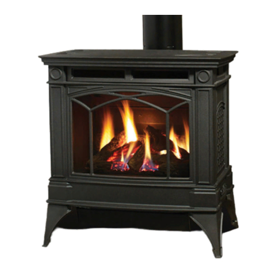
H35 Direct Vent Gas Fireplace
H35 Direct Vent Gas Fireplace
MODELS:
H35U-NG & H35U-LP
WARNING
FIRE OR EXPLOSION HAZARD
Failure to follow safety warnings exactly could result in serious
injury, death, or property damage.
- Do not store or use gasoline or other flammable vapors and liquids in the vicinity of this or any other ap-
pliance.
- WHAT TO DO IF YOU SMELL GAS
• Do not try to light any appliance.
• Do not touch any electrical switch: do not use any phone in your building.
Leave the building immediately.
• Immediately call your gas supplier from a neighbour's phone. Follow the gas supplier's
instructions.
• If you cannot reach your gas supplier, call the fire department.
- Installation and service must be performed by a qualified installer, service agency or the gas supplier.
Tested by:
Certified to/Certifié pour: ANSI Z2.88-2019
920-413
FPI FIREPLACE PRODUCTS INTERNATIONAL LTD. 6988 Venture St., Delta, BC Canada, V4G 1H4
Installer: Please complete the details on the back cover
and leave this manual with the homeowner.
Homeowner: Please keep these instructions for future reference.
Owners &
Installation Manual
02.18.22
Advertisement
Table of Contents

Related Manuals for HAMPTON BAY H35U-NG


Summary of Contents for HAMPTON BAY H35U-NG
- Page 1 Owners & H35 Direct Vent Gas Fireplace H35 Direct Vent Gas Fireplace Installation Manual MODELS: H35U-NG & H35U-LP WARNING FIRE OR EXPLOSION HAZARD Failure to follow safety warnings exactly could result in serious injury, death, or property damage. - Do not store or use gasoline or other flammable vapors and liquids in the vicinity of this or any other ap- pliance.
- Page 2 The H35U model is hand-crafted appliance designed to provide you with all the warmth and charm of a wood fireplace at the flick of a switch. The H35U-NG/LP model were approved by Warnock Hersey for both safety and efficiency. As they also bear the Regency mark, they provide economy, comfort, and security for many trouble-free years to come.
-
Page 3: Unit Dimensions (Top Vent)
dimensions Unit Dimensions (Top Vent) " 699mm " 621mm " 538mm " 41mm " " 427mm 391mm " 671mm ALL PICTURES / DIAGRAMS SHOWN THROUGHOUT THIS MANUAL ARE FOR ILLUSTRATION PURPOSES ONLY. ACTUAL PRODUCT MAY VARY DUE TO PRODUCT ENHANCEMENTS. Hampton®... -
Page 4: Unit Dimensions (Rear Vent)
dimensions Unit Dimensions (Rear Vent) " 699mm " " 427mm 391mm " 671mm Hampton® H35U Direct Vent Freestanding Gas Stove... -
Page 5: Table Of Contents
table of contents Operating Instructions Unit Dimensions (Top Vent) ..............3 Unit Dimensions (Rear Vent) ............... 4 Final Check ..................41 Copy of Safety Label ................6 Operating Instructions ............... 41 Owner's Information Lighting Procedure ................41 Shutdown Procedure ................. 41 Gas Installation Checklist .............. -
Page 6: Copy Of Safety Label
safety label This is a copy of the label that accompanies NOTE: Hampton units are constantly being ® each Direct Vent Freestanding Gas Stove. We improved. Check the label on the unit and if have printed a copy of the contents here for there is a difference, the label on the unit is your review. -
Page 7: Owner's Information
owner's information Gas Installation Checklist REGENCY GAS INSTALLATION CHECKLIST This general checklist does not contain all pertinent installation details or specifics and does not supersede the guidelines in this manual. Your Regency dealer/installer should use it in conjunction with manual instructions. Please follow all local codes and jurisdictions in authority. Customer: Date Installed: Install Address:... - Page 8 REGENCY GAS INSTALLATION CHECKLIST owner's information Finishing If applicable, is only noncombustible material installed in the noncombustible areas? Do clearances meet installation and manual requirements? Do the mantels and/or projections comply with the installation manual? If applicable, was the solid fuel fireplace warning plate installed? Appliance Media Setup Do commands from the remote or wall switch light the pilot and main burner? Are the burner media/log set, glass door, and screen installed per instructions in the manual?
-
Page 9: Copy Of The Lighting Plate Instructions
owner's information Copy of the Lighting Plate Instructions FOR YOUR SAFETY READ BEFORE LIGHTING POUR VOTRE SÉCURITÉ – À LIRE AVANT LA MISE EN MARCHE This appliance must be installed in accordance with local codes, if any; if none, follow the National Fuel Gas Code, ANSI Z223.1/NFPA 54, or Natural Gas and Propane Installation Codes, CSA B149.1. - Page 10 installation MA Code - CO Detector (for the State of Massachusetts only) 5.08: Modifications to NFPA-54, Chapter 10 (2) Revise 10.8.3 by adding the following additional requirements: (a) For all side wall horizontally vented gas fueled equipment installed in every dwelling, building or structure used in whole or in part for residential purposes, including those owned or operated by the Commonwealth and where the side wall exhaust vent termination is less than seven (7) feet above finished grade in the area of the venting, including but not limited to decks and porches, the following requirements shall be satisfied:...
-
Page 11: Important Message
National Fuel Gas Code, ANSI Z223.1 and the current National Electrical Code ANSI/NFPA 70 in the U.S.A., and the current CAN/CSA B149.1 Fuels: H35U-NG is approved for use with natural Gas Installation Code and the current Canadian gas. Electrical Code CSA C22.1 in Canada. -
Page 12: Before You Start
installation Before You Start INSTALLATION AND REPAIR SHOULD BE DONE BY AN AUTHORIZED Safe installation and operation of this appliance SERVICE PERSON. THE APPLIANCE requires common sense, however, we are required by the Canadian Safety Standards and ANSI Stand- SHOULD BE INSPECTED BEFORE ards to make you aware of the following: USE AND AT LEAST ANNUALLY BY A PROFESSIONAL SERVICE PERSON. -
Page 13: General Safety Information
installation General Safety Information 4) Install venting. Refer to the following sections This unit can be installed on a solid combustible where applicable: surface like a wood floor. This unit can also be a. Check all venting requirements. installed directly on carpeting or vinyl. 1) The appliance installation must conform with See "Venting Introduction"... -
Page 14: Locating Your Gas Stove
installation Locating Your Gas Stove Venting Introduction Be sure to check the vent termination clearance requirements from decks, windows, soffits, gas When selecting a location for your stove, ensure The Horizontal Termination Kit and the rigid pipe regulators, air supply inlets and public walkways as that the clearances listed above are met as well venting systems, in combination with the Direct specified in the "Exterior Vent Terminal Locations"... -
Page 15: Fan Installation
H35U-NG / LP AND H35S-NG / LP installation WARNING: Electrical Grounding Instructions 3. Lift the back cover panel up and unit. Take care note to pull on t back cover panel. This appliance is equipped with a three pronged (grounding) plug for... -
Page 16: Exterior Vent Terminal Locations
installation Exterior Vent Terminal Locations Minimum Clearance Requirements Canada Clearance above grade, veranda, porch, deck, or balcony 12"(30cm) 12"(30cm) Clearance to window or door that may be opened 12"(30cm) 9" (23cm) Clearance to permanently closed window Vertical clearance to ventilated soffit located above the terminal within a horizontal distance of 2 feet (61cm) 22"(56cm) 22"(56cm) from the center line of the terminal (check with the local code) -
Page 17: 4" X 6-5/8" Rigid Pipe - Cross Reference Chart Only
installation 4” x 6-5/8” (102 mm x 168 mm) Rigid Pipe - Cross Reference Chart only 4" X 6-5/8" RIGID PIPE CROSS REFERENCE CHART Components from different Manufacturers may not be mixed. Not All Rigid Pipe components are available directly from FPI. Components from different Manufacturers may not be mixed. - Page 18 installation Description Simpson *Selkirk *American Metal *Metal-Fab™ *Security *ICC Excel *Olympia Direct Vent Pro ® Direct Temp™ Products® Sure Seal Secure- Vent® Direct Ventis DV*** Amerivent Direct Attic Insulation Shield 12" 46DVA-IS 4DAIS12 4DIS SV4RSA VDV-AIS04 Attic Insulation Shield 4DAIS12 TM-4AS - Cold Climates 36"...
-
Page 19: Rigid Pipe Venting Systems
installation Rigid Pipe Venting Systems Horizontal or Vertical Terminations Alternate Horizontal Termination Caps WARNING: Do not combine venting components from different venting systems. However use of the the AstroCap and FPI Riser is acceptable with all systems. This product has been evaluated by Intertek for use with Duravent Direct-Vent Pro, Selkirk Direct-Temp, Ameri Vent Direct venting and Security Secure Vent systems. -
Page 20: Rotating 45 O Elbow For Straight Horizontal Terminations
installation Rotating 45 Elbow for Straight Horizontal Terminations 1) Remove the 4 screws of the top panel. 2) Remove all 4 screws that secure the elbow to 3) Rotate the elbow 180 4) Secure the elbow by securing it with the 4 screws. the unit using a 1/4"... -
Page 21: Venting Arrangements - Horizontal Terminations Using Rigid Pipe
installation Venting Arrangements - Horizontal Terminations Using Rigid Pipe The two diagrams show all allowable combina- tions of straight horizontal termination using Rigid Pipe. Restrictor position "A". Only a snorkel or FPI Riser vent may be used as shown. No other termination cap is permitted. Snorkel Termination Riser Vent Termination Venting Arrangements - Straight Horizontal Termination... -
Page 22: Horizontal Venting With Two 90
installation Horizontal Venting with Two 90 Elbows One 90 elbow = Two 45 elbows. Option H + H1 With these options, maxi- mum total pipe length is 30 3' (914 mm) min. 2' (610 mm) max. feet with minimum of 8 feet total vertical and maximum 4' (1.2 m) min. -
Page 23: Vertical Venting With Two 90
installation Vertical Venting with Two 90 Elbows One 90 elbow = Two 45 elbows. Option V + V1 With these options, max. total pipe length is 30 feet 1' (305 mm) min. 3' (914 mm) max. 2' (610 mm) min. with min. -
Page 24: Vertical Termination With Co-Linear Flex System
installation Vertical Termination With Co-linear Flex System Masonry chimneys may take various contours which the flexible liner will accommodate. However, keep THE APPLIANCE MUST NOT BE CONNECTED TO A CHIMNEY FLUE the flexible liner as straight as possible, avoid unnecessary bending. SERVING A SEPARATE SOLID FUEL BURNING APPLIANCE. -
Page 25: Dv Stove Horizontal Termination Vent Kit
DV 2 ft. Stove Vent Kit (Part # 946-116) and DV 4 ft. Stove Vent Kit (Part #946-216) includes all the parts needed to install the H35U-NG/LP Direct Vent unit with minimum horizontal and vertical vent dimensions. For installations that require longer vertical and/or horizontal vents use the Dura-Vent system as shown in the "Dura-Vent Termination Kit"... - Page 26 installation 9) Secure the 4" dia. flex liner to the 4" adaptor with Mill-Pac and 3 of the #8 x 1/2" screws (stainless steel). 10) Slide the decorative Thimble Cover over the pipe sections and secure with 4 screws (#8 x 1-1/2"...
-
Page 27: Dura-Vent Termination Kit
installation Dura-Vent Termination Kit Planning Your Dura-Vent Installation tion.) Select the amount of vertical rise desired for Vent Terminal Locations" section and in your local "vertical-to-horizontal" type installations. building codes. There are two basic types of Dura-Vent Direct Vent To determine the length of vent pipe required for System installations: horizontal termination and ver- Warning: Always maintain required vertical installations, measure the distance from the... -
Page 28: Horizontal Installations - Rigid Vent System
installation Horizontal Installations - Rigid shown in diagram 3. Cut and frame the 10 inch square hole in the exterior wall where the vent Vent System will be terminated. If the wall being penetrated Diagram 1: is constructed of non-combustible material, i.e. Hint: Apply 1) Set the unit in its desired location. -
Page 29: Vertical Termination - Rigid Vent System
installation Note: vent pipe to the vent termination, slide the black Vertical Termination - Rigid Vent a) The horizontal run of vent should decorative wall thimble cover over the vent pipe, System have a 1/4 inch rise for every 1 foot of then slide the Wall Thimble over the vent pipe. -
Page 30: Cathedral Ceilings
installation 7) Ensure vent is vertical and secure the base of the flashing to the roof with roofing rails, slide storm collar over the pipe section and seal with a mastic. 8) Install the vertical termination cap by twist lock- ing it. -
Page 31: Converting Class-A Metal Chimney To Direct Vent System
installation Converting Class-A Metal Termination 4) Pass the flex pipe down through the center of Chimney to Direct Vent System the chimney system, and center the adaptor on the top of the chimney pipe. Drill four 1/8" Top Adaptor diameter holes through the adaptor and into Approved for US Installations Only. -
Page 32: Round Support (Rds) & Square Support (Sqs)
Round Support (RDS) & Square Ensure that all pipe and elbow connections are SYSTEM DATA - H35U-NG in their fully twist lock position. Support (SQS) For 0 to 4500 feet altitude 5) Ensure vent is vertical and secure flashing to the... -
Page 33: Gas Pipe Pressure Testing
installation Gas Pipe Pressure Testing 6) When finished reading manometer, turn off the gas valve, disconnect the hose and tighten the screw (clockwise) with a 1/8" flat screwdriver. The appliance must be isolated from the gas sup- Note: Screw should be snug, but not over ply piping system by closing its individual manual tightened. -
Page 34: Aeration Adjustment
installation Aeration Adjustment The air shutter can be adjusted by moving the adjust- ing wire up or down. The wire is accessed through the bottom. Open the air shutter for a blue flame or close for a yellower flame. The burner aeration is factory set but may need adjusting due to either the local gas supply or altitude. -
Page 35: Conversion Kit #744-969 From Ng To Lp
H35U installation Conversion Kit # 744-969 from NG to LPG Conversion Kit #744-969 from NG to LP for H35U using SIT 820 NOVA Gas Valve THIS CONVERSION MUST BE DONE BY A QUALIFIED GAS FITTER IF IN DOUBT DO NOT DO THIS CONVERSION !! Unscrew the pilot orifice with the Allen key ) Insert a 5/32”... - Page 36 H35U installation 14) Using the Allen wrench as shown in Fig.4, 17) Reverse steps 4) to 2). rotate the screw clockwise until snug, do not overtighten. 18) Attach clear label "This unit has been converted to LPG" near or on top of the serial # decal.
-
Page 37: Optional Brick Panel
installation Optional Brick Panel Log Set Installation 6) Install the brick tabs (refer to Diagram 2). Read the instructions below carefully and refer 1) Remove the cast top and glass front (see Glass to the diagrams. If logs are broken do not use Replacement section in this manual for instruc- Brick the unit until they are replaced. -
Page 38: Double Door Removal
installation 4) Place Rear Log A)02-43 on the two pins on 8) Place the Left Top Log D)02-46 on the pin 12) Position notch in Front Right Log G)02-48 the rear log support. on Log B)02-56 and on top of the cutout on Log F)02-47 and push the bottom right on Log A)02-43. -
Page 39: Wiring Diagrams
installation Wiring Diagrams Caution: Ensure that the wires do If any of the original wires as supplied with the WARNING: Electrical Grounding appliance must be replaced, it must be replaced not touch any hot surfaces and are Instructions with CSA type SEW (200 C) or its equivalent. -
Page 40: Optional Wall Thermostat/Remote Control
installation Optional Wall Thermostat/ CAUTION Remote Control Do not connect the millivolt wall thermostat wires Part #910-407 Basic Wall Thermostat to the 120V wires. Part #910-404/P Programmable Wall Thermostat Part #910-399 Remote Control Thermostat Wire Table A wall thermostat or remote control may be installed if desired. -
Page 41: Operating Instructions
operating instructions Final Check Shutdown Procedure IMPORTANT Before leaving this unit with the customer, the To ignite or reignite the pilot, installer must ensure that the appliance is firing the door to the firebox must be 1) Turn the main gas control clockwise to the correctly. -
Page 42: Copy Of The Lighting Plate Instructions
operating instructions Copy of the Lighting Plate Instructions FOR YOUR SAFETY READ BEFORE LIGHTING POUR VOTRE SÉCURITÉ – À LIRE AVANT LA MISE EN MARCHE This appliance must be installed in accordance with local codes, if any; if none, follow the National Fuel Gas Code, ANSI Z223.1/NFPA 54, or Natural Gas and Propane Installation Codes, CSA B149.1. -
Page 43: Normal Operating Sounds Of Gas Appliances
maintenance Normal Operating Sounds of 2) Clean glass (never when unit is hot), appliance, CLOTHING OR OTHER FLAMMABLE and door with a damp cloth. Never use an Gas Appliances MATERIAL SHOULD NOT BE PLACED abrasive cleaner. ON OR NEAR THE APPLIANCE. It is possible that you will hear some sounds from 3) The heater is finished in a porcelain finish or your gas appliance. -
Page 44: General Vent Maintenance
maintenance General Vent Maintenance Removing Valve 2) Open the 2 latches of the Glass Front. Conduct an inspection of the venting system semi- 3) Lift the Glass Front Assembly up. If your valve requires maintenance or replacement, annually. Recommended areas to inspect as follows: use the following instructions: 1) Check the Venting System for corrosion in areas Note: Always close off the gas supply before... -
Page 45: Installing Valve Assembly
maintenance Installing Valve Assembly 10) Remove all 18 screws holding the burner tray assembly in place. 1) To install a new valve assembly, reverse instruc- tions for removing valve. See assembly steps 1-12. 2) Check for leaks and manifold pressure. See Gas Pressure Test instructions. -
Page 46: Fan Maintenance
H35U-NG / LP AND H35S-NG / LP maintenance Fan Maintenance WARNING: Electrical Grounding Instructions 3. Lift the back cover panel up and pivot out away from the unit. Take care note to pull on the wires attached to the back cover panel. -
Page 47: Gas Maintenance - Recommended Annual Routine
Gas Maintenance maintenance Gas Maintenance - Recommended Annual Routine Recommended Annual Routine Maintenance for Gas Fireplaces, Stoves and Inserts In order for your Regency appliance to continue to provide comfort to your home periodic maintenance must be performed to ensure it is operating at peak efficiency. The items in the list should be checked by a licensed gas service technician during the annual service check. Your unit may require more frequent maintenance checks if you notice any changes in how it operates. Operational changes to look for can include, but are not limited to, extended start up time, increased fan noise, residue/carbon build up, white build up on the glass/firebox, increased operating noise etc. Should any of these or other conditions arise, discontinue use and schedule a service check with your local licensed gas technician. The list below shows items your licensed service technician will need to check and service at least annually. Clean Inspect Check • Glass • Pilot assembly • Voltage on thermocouple/thermopile (mil- • Interior bricks / panels • Burner livolt models) • Burner ports & burner air shutter •... -
Page 48: Main Assembly
parts list Main Assembly Part # Description Part # Description 770-066F Top Pressure Relief Plate 730-550 Burner Assembly NG/LP 14a) W260280 Top Pressure Relief Plate Gasket 740-542 Door Assembly 904-012 Top Pressure Relief Bolt (Each) 743-100 Safety Screen 742-117 Pressure Relief Frame 742-160 Front Brick Inlay 16a) W260260... -
Page 49: Burner & Log Assembly
parts list Burner & Log Assembly Part # Description 910-246 Switch 2-Way 910-568 Novasit Gas Valve NG/LP 820 SIT High/Low 0.820.852 22a) 744-574/P Valve Assembly - NG 22a) 744-576/P Valve Assembly - LP 630-008 Valve Assembly Gasket 730-550 Burner Tube Assembly - NG/LP 730-528 Rear Log Bracket Assembly 260-565... -
Page 50: Optional Accessories
parts list Optional Accessories Part # Description 744-917 Fan Kit Complete 740-901 Brick Panels Rustic Brown 740-902 Brick Panels Old Town Red 744-969 LP Conversion Kit 910-399 Fire genie Remote Control 910-407 Basic Wall Thermostat 910-404/P Programmable Wall Thermostat W902005 Vent Paint Brown N/S = Not Shown Hampton®... - Page 51 notes Hampton® H35U Direct Vent Freestanding Gas Stove...
-
Page 52: Warranty
warranty Limited Lifetime Warranty FPI Fireplace Products International Ltd. (for Canadian customers) and Fireplace Products U.S., Inc. (for U.S. customers) (collectively referred to herein as “FPI”) extends this Limited Lifetime Warranty to the original purchaser of this appliance provided the product remains in the original place of installation. The items covered by this limited warranty and the period of such coverage is set forth in the table below. - Page 53 warranty At all times FPI reserves the right to inspect reported complaints on location in the field claimed to be defective prior to processing or authorizing of any claim. Failure to allow this upon request will void the warranty. All warranty claims must be submitted by the dealer servicing the claim, including a copy of the Bill of Sale (proof of purchase by you).
- Page 54 warranty Limitations of Liability: The original purchaser’s exclusive remedy under this warranty, and FPI’s sole obligation under this warranty, express or implied, in contract or in tort, shall be limited to replacement, repair, or refund, as outlined above. IN NO EVENT WILL FPI BE LIABLE UNDER THIS WARRANTY FOR ANY INCIDENTAL OR CONSEQUENTIAL COMMERCIAL DAMAGES OR DAMAGES TO PROPERTY.
- Page 55 warranty Product Registration and Customer Support: Thank you for choosing a Regency Fireplace. Regency strives to be a world leader in the design, manufacture, and marketing of hearth products. To provide the best support for your product, we request that you complete a product registration form found on our Web Site under Customer Care within ninety (90) days of purchase.
- Page 56 warranty Hampton® H35U Direct Vent Freestanding Gas Stove...
- Page 57 notes Hampton® H35U Direct Vent Freestanding Gas Stove...
- Page 58 notes Hampton® H35U Direct Vent Freestanding Gas Stove...
- Page 60 Installer: Please complete the following information Dealer Name & Address: ______________________________________________ ___________________________________________________________________ Installer: ___________________________________________________________ Phone #: ___________________________________________________________ Date Installed: ______________________________________________________ Serial #: ____________________________________________________________ Printed in Canada Hampton is a trademark of FPI Fireplace Products International Ltd. © Copyright 2022, FPI Fireplace Products International Ltd. All rights reserved.
Need help?
Do you have a question about the H35U-NG and is the answer not in the manual?
Questions and answers