Table of Contents
Advertisement
Advertisement
Table of Contents

Related Manuals for Worldline VALINA


Summary of Contents for Worldline VALINA
- Page 1 VALINA Integration guide Digital Payments for a Trusted World...
-
Page 2: Table Of Contents
Contents List of abbreviations Logistics information Terminal label Packaging Palleting VALINA spare parts Approvals Certifications Approvals related to use in a railway/ t ramway environment VALINA key features Contactless cards/devices Chip (contact) cards Magstripe cards Key hardware features include Network considerations Appearance Safety Operating safety Repairs and end-of-life Security recommendations Integrators Merchants Installing VALINA Selecting a location Packaging Installing the terminal Installing the 4G antenna Installing the 4G communications board Ports and pin-outs RS-232 interface Ethernet 10/100 Mbit USB-A (host) interface USB-B (device) interface Power supply – TTL Power supply – MDB Proximity sensor Power management... - Page 3 Figures Figure 1: Terminal label Figure 2: MAC address label Figure 3: Card reading with VALINA Figure 4: VALINA and PIN privacy shield – example Figure 5: VALINA – front view (left) and back view Figure 6: General dimensions Figure 7: Opening in front plane and positioning studs Figure 8: Maximum inclination for mounting Figure 9: Power connections – Microfit (left), MDB (centre), RS232 (right) Figure 10: Strain-relief points on VALINA mounting-plates Figure 11: VALINA with TELECOM cover in place Figure 12: Fitting SAM cards Figure 13: Inserting the micro SD card Figure 14: 4G antenna for VALINA – components Figure 15: TELECOM cover Figure 16: 4G communications board Figure 17: Power supply/data connectors on the VALINA Figure 18: Double-pulse timing for wake-up Figure 19: JTAG/Debug port...
-
Page 4: List Of Abbreviations
1 List of abbreviations Europay Mastercard Visa (card payment transactions) Electromagnetic compatibility (electric) Electronic Cash Register PCI PTS Payment Card Industry PIN Transaction Security Federal Communications Commission Near Field Communication WEEE Waste of Electrical and Electronic Equipment VMC Vending Machine Controller The information provided in this documentation has been compiled which relate to instances of material or immaterial damage, which are with the greatest level of care. Due to further developments in the attributable to the use or non-use of the information provided and/or field of electronic payment transactions, as well as the technology, the use of incorrect or incomplete information, are excluded in princi- changes may occur that lead to deviations from these instructions. ple insofar as no deliberate or grossly negligent misconduct may be proven with respect to W orldline. W orldline shall therefore accept no liability for the up-to- d ateness, completeness or accuracy of the information provided in these oper- Please visit our homepage worldline.com/merchant-services to view ating instructions. Any claims for liability asserted against W orldline the most up-to-date version of this document. -
Page 5: Logistics Information
2 Logistics information TERMINAL LABEL Examples of product labels are provided to show what information is given on each label. Minor differences in layout may occur. The VALINA terminal label shows: • M aker’s name: Worldline SA/NV • M odel name: VALINA • A rticle number, referring to the specific terminal hardware. This number identifies the specific terminal hardware and customisations, and is used for certification purposes. It is not the same as the commercial article number mentioned on the packaging box, which is customer-specific. • S erial number: – human-readable, for example Serial N°: ABC1234 – barcode • P roduction date in the format yywk, so 1549 for week 49 in 2015 • C ountry of origin: Made in Indonesia Figure 1: Terminal label • V oltage and current: 12 V 2 A • S afety labels, for example CE, FCC... -
Page 6: Packaging
• E uropean directive 1907/2006/EU on Registration, Evalu- • P CI PTS ation, Authorisation and Restriction of Chemicals (REACH), • E U directive 2014/53/EU (RED – radio equipment directive) intended to ensure chemicals are produced and used in • E U directive 2014/35/EU (LVD – low voltage directive) ways that lead to the minimisation of significant adverse • E U directive 2014/30/EU (EMC – electromagnetic com- effects on human health and the environment. patibility directive) • E uropean directive 2012/19/EU on Waste Electrical and E lectronic Equipment (WEEE), encouraging collection, t reatment, recycling and recovery of such items. • T he VALINA is labelled with the WEEE-logo. -
Page 7: Approvals Related To Use In A Railway/ Tramway Environment
FCC 47 part 15 APPROVALS RELATED TO USE IN A RAILWAY/ The equipment has been tested and found compliant to the TRAMWAY ENVIRONMENT requirements of the FCC 47 part 15 for digital devices. Vibrations IC ICES-003 and RSS-210 Equipment used in a railway/tramway environments must be This class B equipment has been tested and found compliant able to resist vibrations in the vehicles where it is installed, to Canadian ICES-003 and RSS-210 for digital devices. as measured by IEC standard 60068. FCC rules: 15.105 EN 50155 The equipment has been tested and found to comply with the Railway applications. Rolling stock. Electronic equipment. limits for a Class B digital device, pursuant to Part 15 of the FCC Rules. These limits are designed to provide reasonable EN 50125-1 protection against harmful interference in a residential instal- Railway applications. Environmental conditions for equipment. lation. This equipment generates, uses and can radiate radio Rolling stock and on-board equipment. frequency energy and, if not installed and used in accordance with the instructions, may cause harmful interference to Electromagnetic interference radio communications. However, there is no guarantee that Included in EU directive 2014/53/EU (RED – radio equipment interference will not occur in a particular installation. If this directive) equipment does cause harmful interference to radio or tele- vision reception, which can be determined by turning the Lightning-strikes equipment off and on, the user is encouraged to try to correct... -
Page 8: Valina Key Features
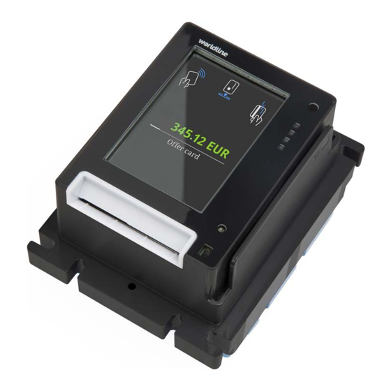
4 VALINA key features The VALINA is an intelligent all-in-one terminal for unattended The VALINA has been designed to provide a complete solution payments with and without PIN, supporting a range of stand- for EMV payments, and can run either newly-developed ards including EMV and Mifare. It handles payments by chip Android apps or legacy apps (written for the MAPS platform) card, NFC cards and devices, and magstripe card. from Worldline. It is PCI certified, SRED included. Figure 3: Card reading with VALINA CONTACTLESS CARDS/DEVICES KEY HARDWARE FEATURES INCLUDE: The “landing zone” for contactless payments is: • 3 .5" touch TFT colour display for an enjoyable payment • E asily recognizable and accessible e xperience • M arked by the contactless symbol • S mall footprint matches EVA/CVS 1.3 standards for The contactless symbol is placed where the signal is S tandard Door Module (SDM) dimensions, making integra- s trongest and shows the “landing zone” where customers tion in v ending machines easy. -
Page 9: Network Considerations
NETWORK CONSIDERATIONS Because Spica packages for the VALINA are significantly larger than their older SAMOA equivalents, broadband There are two options for connecting a VALINA to the outside throughput and latency become more critical. Teleloading has world: specific requirements, including a minimum transfer-rate • i ntegrated comms card supporting mobile broadband of 4 kbps over 30 seconds. (GPRS, EDGE, 3G, 4G) • o nboard ethernet interface supporting landline broadband Acceptable transfer-rates and latency are easier to obtain using landlines. Please note that • We cannot influence/take responsibility for the quality of any broadband solution. • W e will not support (or parameterize) hybrid solutions such as the use of mobile broadband routers/modems behind the E thernet interface because there is too much dependency on the quality provided by the mobile operator, often impacted by deep indoor signal reception issues or Faraday-cage impact of the machine. APPEARANCE Figure 4: VALINA and PIN privacy shield – example Figure 5: VALINA – front view (left) and back view For more information on connectors, see Ports and pin-outs, on page 19. For more information on integration dimensions, see General dimensions, on page 12. -
Page 10: Safety
• u se only the power adaptor supplied, or a power adaptor functioning, breakdowns or any anomaly that may result from compliant with the appropriate specifications. incorrect handling of the VALINA. We decline any liability if • d isconnect the power adaptor before cleaning the housing the instructions and precautions contained in this manual are and for servicing or repair. not observed. Never If you notice that any VALINA component blocks, does not fit, • d rop, throw, slam or vibrate the VALINA. or shows any other malfunction, contact our local service team. • l et oil, water or other liquids enter the VALINA. Do not try to repair or alter it in any way. • u se extension cables to extend the power cable between the power adaptor and the VALINA. • c onnect any unused cables to the VALINA. Use only accessories (power adaptor, cables and so on) pro- vided by us or by an approved source. • s tore, install or use the VALINA – n ear any source of excessive voltage fluctuations,... -
Page 11: Security Recommendations
6 Security recommendations Security features are integrated at all levels of the VALINA MERCHANTS design, from the external housing to the “system-on-chip” at the heart of the terminal. To combat fraud from external For security reasons, merchants are advised to check their sources, regular visual checks are essential. VALINA every working day and make sure that: • t here is no sign of unusual cables connected anywhere INTEGRATORS on the terminal. • t here is no foreign object in either of the card-readers. Integrators must implement appropriate procedures to guar- • t he terminal is not displaying any warning message. antee that every installation on the field is checked regularly. • t he housing is not visibly damaged. The purpose of the checks is to make sure that: • t he terminal serial number (on the label) corresponds • n o camera has been set up to track cardholder activity. to the inventory. • n o skimming device has been attached. -
Page 12: Installing Valina
7 Installing VALINA • Read Operating safety, on page 10, before you start • Make sure the vending machine has the necessary front installing a VALINA. panel/top panel openings and spot-welded connection • Make sure that: bolts, and that the weld seams are within permitted limits. – t here is no sign of unusual cables connected anywhere • Make sure the front panel of the vending machine is on the VALINA. smooth and rigid with no unfinished edges on any of the – there is no foreign object in either of the card-readers. holes or openings. – the terminal is not displaying any warning message. • Make sure the VALINA cannot be removed from the vending – the housing is not visibly damaged. machine after integration. – t he terminal serial number (on the label) corresponds to the inventory. 101.59 88.00 30.80 44.76 welded studs M4 × 25 Figure 6: General dimensions For exact measurements, including tolerances, download the VALINA mounting instruction from worldline.com/merchant-services/download. Figure 7: Opening in front plane and positioning studs... -
Page 13: Selecting A Location
• Select a location on the machine that is conveniently PIN privacy. a ccessible. • For the convenience of the technician, make sure there • On the front side of the vending machine, make sure that: is sufficient space on the vending machine to: – the VALINA fits in the mounting position. – access the ground connection. – the VALINA faces the cardholder and will be clearly visible. – g uide the cables without folding them, and use – the display is readable. cable ties. – the card slot is accessible. – f it the mounting brace that fastens the terminal tightly • Avoid a position that exposes the VALINA to rain or hostile into the machine weather. – access the rear side of the VALINA. • Mount the VALINA vertically (recommended), and never • The maximum permitted length of the cable between the less than 50 ° from the horizontal: this reduces the risk of VALINA and the vending machine controller (VMC) is 3 m. water getting into the chip-card reader. PACKAGING Quantity Item 50 ° 90 ° VALINA... -
Page 14: Installing The Terminal
INSTALLING THE TERMINAL Step 2: Mount the VALINA in the vending machine 1. Line up the VALINA with the front panel opening on the v ending machine. 2. Clamp the EVA frame to the rigid front plate of the machine Note using four locknuts. If you are going to install a 4G communications board Note: These locknuts are not included in the terminal and antenna, prepare the vending machine first: see package. Installing the 4G antenna, on page 17, for instructions. 3. Tighten the locknuts in a Z-pattern. To avoid damaging the VALINA, do not over-tighten the nuts. If you are going to install a SIM card or 4G comms 0.7 Nm is recommended, depending on the material the board (described on page 18), complete this task front plate is made from. before installing the VALINA in the vending machine. After mounting the VALINA on the vending machine, continue by connecting the power and communications cables. Step 1: Check the gasket positioning The lugs (pins) in the rubber should fit into the terminal openings above and below. -
Page 15: Figure 10: Strain-Relief Points On Valina Mounting-Plates
Step 4: Power up VALINA and fasten cables 1. Open the TELECOM cover The VALINA requires an external power supply, using one Remove the retaining screw of the TELECOM cover of these three options: and open the cover. • connector 1 – 12 V DC 2A (RJ45 connector) • connector 5 – 12 V DC 2A (Microfit connector) • connector 6 – 24–45 V DC (MDB connector) Note The VALINA cannot be powered through any other port. To reduce wear on the connectors, use a cable tie to fasten the cables to the strain-relief points on the VALINA mounting- p lates. 6 MDB Figure 11: VALINA with TELECOM cover in place 2. Open the SAM holder and insert SAM card. Open the SAM holder (with the two bar-code labels on) and insert one or two SAM cards as shown. -
Page 16: Figure 13: Inserting The Micro Sd Card
Step 6: Install micro SD card – optional 1. Open the TELECOM cover. Remove the retaining screw of the TELECOM cover and open the cover. 2. Insert the microSD card in the holder as shown. 6 MDB Figure 13: Inserting the micro SD card Note If you will be installing an optional communications board, do not close the TELECOM cover yet. If you are using a retaining screw for the cover, use one 8 torx screw (included). Do not over-tighten the screw. -
Page 17: Installing The 4G Antenna
±0.8 Antenna housing SMA connector with coupling nuts Self-adhesive sealing pad Antenna cable labels Threaded tube Split nut Cables (2000 mm) Split washer Figure 14: 4G antenna for VALINA – components Step 1: Drill the mounting hole Step 5: Press the antenna firmly into position Drill the mounting hole in the top of the vending machine. The mounting hole must be 20 mm in diameter, and it Step 6: Position the two cables is r ecommended to drill it in the centre of the top panel. 1. Put the two cables inside the split washer and slip the washer over the threaded tube. Step 2: Remove the split washer and split nut 2. Put the two cables inside the split nut, and screw the nut... -
Page 18: Installing The 4G Communications Board
1. Slide the microSIM card cover towards the bottom of the VALINA to unlock it. Figure 16: 4G communications board 2. Open the cover, insert the microSIM card and close the cover. 3. Slide the microSIM card cover towards the top of the VALINA to lock it. Step 5: Connect cables to 4G communications board 1. Remove and throw away the two knock-outs on the Step 4: Fit the 4G communications board in the VALINA T ELECOM cover. 1. Hold the 4G communications board with the two SMA 2. Replace the TELECOM cover, guiding the two SMA c onnectors facing you and at the lefthand side of the board. c onnectors through the holes. 2. Slide the 4G communications board under the clips on 3. Replace the 8 torx screw for the TELECOM cover; the left. -
Page 19: Ports And Pin-Outs
8 Ports and pin-outs There are six sockets at the back of the VALINA: Note • four for data/peripherals VALINA cannot be powered through the • one for power supply and data/peripherals E thernet i nterface. • one for power supply only The VALINA is powered from an external power adaptor through port 5 (TTL), port 6 (MDB) or port 1 (RJ45). Pinout for Ethernet 10 Mbit connector T he VALINA is CE certified in combination with the P ower t ech Description Direction ADS 0271-B adaptor. If any other power supply is used, they have to be compliant with local safety requirements and regulations. USB-A (HOST) INTERFACE The VALINA is fitted with a USB 2.0 high speed (up to 480 Mbps) host interface, which can be used to connect to a USB stick or other storage device. Note VALINA cannot be powered through the USB host Figure 17: Power supply/data connectors on the VALINA interface: it always needs an external power supply. -
Page 20: Power Supply - Ttl
POWER MANAGEMENT Pinout for USB-B interface Description Direction VALINA is equipped with smart power management profiles. Each profile puts the terminal in a different state and supports different ways to wake up the terminal. Using the different D– bidirectional p rofiles in a smart way will minimise the amount of energy the VALINA requires when not in use for a transaction. The infor- bidirectional mation below is indicative. Measurements in the field may differ, depending on applications that might call for additional resources. POWER SUPPLY – TTL Stand-by profile The TTL interface is a surface-mounted, dual-row, 6 circuit Consumption: connector (Molex Microfit connector) with a press-fit metal • 0.019 W retention clip. Wake-up possibilities: Pinout for Microfit 43045-0616 interfaces • external trigger via the TTL I/O interface • reset button on the back (not accessible by cardholder) Direction • double pulse via the TTL I/O interface... -
Page 21: Jtag/Debug Port
9 JTAG/Debug port For development and repair purposes, the VALINA is equipped The JTAG/Debug Port is also available via a pinheader with with a JTAG/Debug port, underneath the TELECOM cover. a pitch of 1.27 mm, which is available on prototypes and This port can be used to connect a PACIFIC Debug Interface development terminals. for debugging and logging purposes. This port can also be used to connect a JTAG Interface for repair and reflash Pinout for JTAG/Debug port – pinheader purposes. Description Description The following interfaces are available on this port: SRSTn • JTAG-interface towards the ASIC 3.3V • 3.3V UART interface towards Core 1 (secured – UART_A3) • 3.3V UART interface towards Core 2 (unsecured – UART_B3) UART4_ RXD (debug) UART4_TXD (debug) UART5_ RXD (debug) TRSTn UART5_TXD (debug) Figure 19: JTAG/Debug port The JTAG/Debug port uses a spring-loaded connector with 2.54 mm pins. Pinout for JTAG/Debug port – springport... -
Page 22: Cleaning
• Let dirt enter the card readers. 3. Clean the display with a soft dry anti-static cleaning cloth. • Use detergents, solvents, alcohol or abrasive products. 4. Clean card readers every two weeks, with an appropriate These products may damage the surface and make cleaning card. Contact your local service team for informa- t rans p arent parts opaque. tion about cleaning cards. After cleaning, do not forget to re-connect the equipment. 11 Repairs and end-of-life All servicing other than the actions described in this manual STEP BY STEP must be performed by our local service team. Inspect the terminal for completeness, signs of intrusion and When a VALINA or any of its accessories is at the end of its tampering, as explained under Security recommendations, life, it must not be simply thrown away, given away or sold on. on page 11. As terminal owner, you are responsible for the correct decom- missioning of terminals and their components or accessories If you find any evidence of tampering, report the problem to at their end of life. us and keep the terminal available for possible forensic inves t igation. Remember that: 1. If you do not find any evidence of tampering, dispose of the • Security awareness requires erasing cryptographic compo- terminal following local rules and regulations for disposal nents securely and completely. -
Page 23: Appendix Technical Specifications
Dust-/waterproof rating IP65 Processing capabilities Hardware cryptographic accelerators Protection classification vandal-proof class IK09 Memory 512 Mbytes RAM SOFTWARE 4 Gigabytes Flash memory Micro USD • Android and Linux® OS • Linux-based development kit (C and Java™) Power supply • Secured remote download of software 12 V DC, 2A (when using Microfit) 24–45 V DC (when using MDB) Proximity detector Weight 573 g Your local point of contact can be found at: worldline.com/merchant-services/contacts...
Need help?
Do you have a question about the VALINA and is the answer not in the manual?
Questions and answers