Table of Contents
Advertisement
Advertisement
Table of Contents

Related Manuals for Worldline Self/7000


Summary of Contents for Worldline Self/7000
- Page 1 Self/7000 Self/8000 Integration Guide Digital Payments for a Trusted World...
-
Page 2: Table Of Contents
Table of content List of abbreviations 1 Introduction 1.1 Self/7000 and Self/8000 Payment Solution Presentation 1.1.1 Self/7000 1.1.2 Self/8000 1.2 Key hardware features 1.3 Network considerations 2 Description of modules 2.1 Self/7000 2.1.1 Connectivity and communications diagrams 2.1.2 Mechanical standard 2.1.3 Technical characteristics 2.1.4 Output connectors description 2.1.5 Wake-up function 2.2 Self/8000 2.2.1 Connectivity and communications diagrams 2.2.2 Mechanical standard 2.2.2.1 EVA standard... - Page 3 The information provided in this documentation has been compiled which relate to instances of material or immaterial damage, which are with the greatest level of care. Due to further developments in the attributable to the use or non-use of the information provided and/or field of electronic payment transactions, as well as the technology, the use of incorrect or incomplete information, are excluded in princi- changes may occur that lead to deviations from these instructions. ple insofar as no deliberate or grossly negligent misconduct may be Worldline shall therefore accept no liability for the up-to-dateness, proven with respect to Worldline. Please contact your account manager completeness or accuracy of the information provided in these oper- for the most up-to-date version of this document. ating instructions. Any claims for liability asserted against Worldline...
-
Page 4: List Of Abbreviations
List of abbreviations Cardholder Verification Method Electro Magnetic Compatibility European Vending Association Ground Liquid Crystal Display Local Loading Tool Random Access Memory Universal Serial Bus Contactless... -
Page 5: Introduction
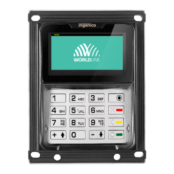
1 Introduction SELF/7000 AND SELF/8000 PAYMENT SOLUTION PRESENTATION The Self/7000 and Self/8000 are Worldline’s new modular The terminals have been designed to provide a complete solution for EMV payments and run ep2 applications from unattended payment terminals. They are designed to fit into any kiosk of any area of application (petrol, transport, vending, Worldline. The terminals are PCI PTS 6.x certified, SRED parking, etc.). Usage can be in- or outdoors, resisting to harsh included. weather conditions. The Self/8000 must always be connected to the master device Self/7000. The two-component terminal is the successor of the iSelf series and XENTEO Eco to renew your experience of unattended payments. 1.1.1 SELF/7000 The Self/7000 is a hybrid card reader offering contact, chip PIN code entry. The Self/7000 terminal is designed to fit into and magnetic card processing. It must be connected to a any kiosk via rear installation and it complies with EVA EPS Self/8000 device to enable contactless card processing and (Compact Door Module). Product views: 1.1.2 SELF/8000 The Self/8000 is a compact PINPAD device supporting NFC/ thanks to an easy installation either on the surface or rear contactless card processing and PIN entry via a conventional mounted and complies with EVA EPS (Standard Door Module). keyboard. The Self/8000 can never be used as a standalone The Self/8000 is also written Self/8000 CL to highlight the device. This compact terminal is designed to fit into any kiosk contactless capability. -
Page 6: Key Hardware Features
Product views: EVA: ARTEMA: KEY HARDWARE FEATURES Self/7000 Self/8000 MDB and 4G can be offered using add-on boxes. Small footprint complies with EVA/CVS 1.3 standard for Onboard Ethernet, serial interface, USB host and USB the dimensions of the Standard Door Module (SDM) or, for device. the ARTEMA version, with the standards of other suppliers. NETWORK CONSIDERATIONS Worldline supports two options for connecting a Self terminal: Worldline will not support (or parameterise) hybrid solutions, • Add-on box for mobile broadband (4G) such as the use of mobile broadband routers/modems behind • Onboard ethernet interface supporting fixed broadband the ethernet interface as there is too much dependency on the quality provided by the mobile operator, which is often Please note that Worldline has no control over and can’t be affected by indoor signal reception issues or Faraday cage held responsible for the quality of broadband solutions. of the device. -
Page 7: Description Of Modules
2 Description of modules SELF/7000 2.1.1 CONNECTIVITY AND COMMUNICATIONS DIAGRAMS Self/7000 MMC slot 9 – 1 6 V Max Power Serial port COM0 USB SAM slot Serial port COM2 Slave Chip & Magnetic cards USB-Host 1 USB-Host 2 Ethernet Self/8000 Power or MDB Box (Optional) Audio Radio (Optional) -
Page 8: Mechanical Standard
2.1.2 MECHANICAL STANDARD The dimensions are given in mm. -
Page 9: Technical Characteristics
Power supply 9 V – 16 V 2 A Platform Tetra Memory 512 Mb SDRAM and 512 Mb Flash Link 2× USB host (USB-A) 1× USB device(USB-B) 2× RS232 (RJ11 and JST) 1× Ethernet (RJ45) 2× Add-on BOX connection 1× Self/8000 (HDMI) Functionality Self/7000 Buzzer Audio connector ouput 1× Maintenance Button 1× µSD 2× SAM Wake-up mechanism on RS232 connectors Wake-up mechanism on card entry 2.1.4 OUTPUT CONNECTORS DESCRIPTION USB device • The device uses type B USB cable. • Cable length should not exceed 5 m. COM0 and COM2 link • The device can be connected to the serial port • The connector type is RJ11 for COM0 and JST for COM2. - Page 10 SAM & μSD Installation Buzzer 1. Disconnect the device from cable power supply. The buzzer is controlled by the payment application. 2. Remove the black silicon part (SAM1, SAM2, uSD). The frequency is driven by the software. 3. Insert the SAM cards in SAM slot 1 and/or slot 2. Take care about the corner angle location. Card entry 4. Insert the SD card in μSD as shown in the picture below. Card entry information (guidance) can be displayed on 5. Replace the black silicon part. the screen of the Self/8000. Keyboard A keyboard must be connected to the Self/7000 device which is the Self/8000. 10 × digit key, 4 × function key (correction/valid, cancel, reserved) and 2 contextual keys (*, #, or, up/down). Maintenance button and LED The device has a maintenance button at the back. Maintenance button To restart the device, press the button until the blue LED lights are on. Audio output The device shall be connected to a 4 ohm speaker – 2.8 W for optimal results. Connector on the board: JST SM03B-SRSS-TB.
-
Page 11: Wake-Up Function
Wake-up mechanism The wake-up PIN is set to “0” by the person who triggers the The device is designed to save power with a “stand-by mode”. wake-up (e.g. an external button). To wake up the terminal you have to maintain the “0” level for at least 1 second. When using stand-by-mode, use the wake-up mechanism with PIN 2 of COM0 or COM2 connection. Wake-up pin state HZ (high Impedance) Stand-by authorized Drive to “0” Wake-up/Stand-by unauthorized Self/7000 COM0 & 2 1 – GND 2 – Wake-up HZ = > Stand-by “0” = > Wake-up Any devices design to be compliant. HZ = > Stand-by “0” = > Wake-up Recommended circuit implementation Wake-up entry To IUN Product Warning: DIODE Voltage on this pin must not exceed 10 V... -
Page 12: Self/8000
SELF/8000 2.2.1 CONNECTIVITY AND COMMUNICATIONS DIAGRAMS Self/8000 Display 5V5 Max Keyboard Power USB Contactless cards Slave 2.2.2 MECHANICAL STANDARD 2.2.2.1 EVA STANDARD... - Page 13 The dimensions are given in mm.
-
Page 14: Artema Standard
2.2.2.2 ARTEMA STANDARD The dimensions are given in mm. -
Page 15: Technical Characteristics
2.2.3 TECHNICAL CHARACTERISTICS Mass Self/8000: 963 g Dimensions 131.3 × 100 × 40.7 mm (height × width × depth) Power supply 2 A 5V5 Platform Tetra Memory Internal memory only Link 1× Self/7000 (Pin Out) Functionality Self/7000 Contactless card reader 2.5" Graphic display (320 × 160) Buzzer 1× Maintenance button IDMI port, connection to Self/7000 IDMI port, connection to Self/8000 Buzzer The buzzer is controlled by the payment application. Contactless LEDs & contactless logo The information given by this signal is shown on the display according to the EMVco rules. -
Page 16: Wake-Up Function
2.2.4 WAKE-UP FUNCTION Wake-up mechanism The Self/8000 is designed to save power with a “stand-by mode”. When using the stand-by-mode, the following wake-up mechanism can be applied: Pin 2 of COM0 link. Self/8000 COM0 & 2 1 – GND 2 – Wake-up HZ = > Stand-by “0” = > Wake-up Any devices design to be compliant. HZ = > Stand-by “0” = > Wake-up Recommended circuit implementation Wake-up entry To IUN Product Warning: DIODE Voltage on this pin must not exceed 10 V Wake-up command MOSFET N As the pin is high impedance in stand by mode, any current... -
Page 17: Main Accessories
• Avoid the use of pressurised liquids. • Use a soft cloth slightly soaked in soapy water to clean • Do not expose the terminal to direct sunlight. the outside of the terminal. • The glass has a special surface treatment, thus it must be cleaned carefully. 2.2.8 STANDARDS Electrical consumptions Environmental specifications continued Storage conditions: • Max power supply: 5V5 (provided via Self/7000) • Front face shock resistance: IK10 • Backup battery life: 6 years of storage • Vibrations resistance: NF EN 60068-2-6 and the below Temperature and humidity conditions (10 tests sequences per axis): Operating and storage conditions: • From 5 Hz to 9 Hz with 3.3 mm amplitude • From 9 Hz to 200 Hz with 10 m/s² acceleration • Operating conditions: • From 200 Hz to 500 Hz with 15 m/s² acceleration – Relative humidity: 85% non-condensing at 40 °C • Endurance 30 mn on each resonance frequency... -
Page 18: Product Installation
– T o avoid reflections and to guarantee readability, do not local requirements: • Select a location on the machine that is conveniently expose the display to direct sunlight. accessible on the front side of the vending device. – F or the security of the cardholder, make sure that PIN privacy is guaranteed. Make sure that: – T he Self terminals fit in the mounting position – L ocate the display outside the field of vision of c ameras, – T he card reader (Self/7000) and Pinpad/NFC device mirrors and away from stairs. (Self/8000) faces the cardholder and is clearly visible • Check all local regulations and requirements for PIN – T he display is readable p rivacy. There is extended information about this topic in the Self Security Policy, available on the PCI website. – T he card slot is accessible • Make sure there is sufficient space in the vending machine to: Important note: It is required to use ESD protective clothing – F it the mounting brace that fastens the terminal tightly... -
Page 19: Procedure For Product Installation
• The terminal must never be put in or left at a location terminal can detect any “tampered state”. In this state, the where it could be stolen or replaced by another device. terminal repeatedly flashes the message ”Alert Irruption!” • You are strongly advised to perform regular checks on and further use of the terminal is not possible. If you the chip card reader. observe the “Alert Irruption!” message, you should contact the terminal helpdesk immediately. PROCEDURE FOR PRODUCT INSTALLATION 3.4.1 SELF/7000 PRODUCT INSTALLATION The rating plate with PCI hardware version number must be Product gasket visible for inspection once the device is installed. The label is To ensure the IP ratings, the gasket must be assembled only visible on the inside when opening the machine. c orrectly. The centreline of operating controls or input/output compo- nents must be at least 400 mm above the ground. Front gasket IP rating is related to front face only: Self/7000 IP54 Evacuation pipe This accessory is delivered for Self/7000 to guide water inside the kiosk. Take care about pipe hose orientation as described below:... -
Page 20: Add-On Boxes
Cables holder A cable holder is supplied with the Self/7000 product. It is recommended to connect the cables to the Self/7000 device first and then place the cable holder as describe below. 3.4.2 ADD-ON BOXES Self/7000 can be upgraded by 2 types of add-on boxes: Installation • The first is dedicated to MDB features, power only or Box mounting full MDB. • The second is dedicated to communication. Depending on the reference, it is possible to have Bluetooth and/or Radio link (3G/4G EU/US/AUS standard). Removable gasket part Step 1: Power off Step 2: Remove the relevant cap from the rear casing Step 3: I nsert the add-on box • Slot 1 for MDB or PWR box MDB box Radio box • Slot 2 for radio box Step 4: Screw the two screws using torque: 0,8 Nm Self/000x – Radio Box Antenna mounting... -
Page 21: Self/8000 Product Installation
3.4.3 SELF/8000 PRODUCT INSTALLATION The rating plate with PCI hardware version number must be Product gasket visible inside the machine once the device is installed. To ensure the IP ratings, the gasket must be assembled c orrectly. Therefore carefully check the right positioning of The centreline of operating controls or input/output compo- the lugs into the corresponding openings of the terminal. nents must be at least 400 mm above the ground. Front gasket Caution IP rating is related to the front face only: Caution Self/8000 IP65. It is required by safety regulations that the EVA plate must permanently be connected to GND. Caution It is important that the device footprint surface on the kiosk must be flat and cleared of any holes and burrs to prevent from dust and water penetration into the kiosk (IP65 standard). Rubber at the rear of the product guarantees waterproofness between the EVA plate and the product. Waterproofness between the EVA plate and the kiosk panel should be guaranteed by the rubber on the EVA plate. -
Page 22: Installing The Modular Terminal
Step 3: Cabling After mounting the terminals into the vending machine, prepare the vending machine first. c ontinue by connecting the communication cables. If you are going to install a SIM card or 4G comms board, complete this task before installing the comm-box on the terminal and before mounting the terminal in the vending machine. IDMI port, connection to Self/7000 Step 1: Check the gasket positioning Lugs (pins) in the rubber should fit into the terminal o penings IDMI port, above and below. connection to Self/8000 Step 2: Mount the modular terminal in the vending machine 1. Line up the terminal with the front panel opening on the vending machine. -
Page 23: Safety
4 Safety Follow the guidelines in this manual when integrating the Use only accessories (power adapters, cables, etc.) provided Self/7000 and Self/8000. Neither Worldline nor its supplier by your vendor or by an approved source. will bear any responsibility or costs for malfunctions, break- downs or anomalies that may result from incorrect handling Make sure that the Self terminal has completed the necessary of the payment terminals. Worldline disclaims all liability if steps to load the application and keys. the instructions and precautions contained in this manual are not followed. Security features are integrated in all levels of the Self termi- nal design, from the external housing to the chipset at the If you notice that any Self component blocks, does not fit, heart of the terminal. Regular visual checks are essential to or shows any other malfunction, contact your vendor. Do not combat fraud from the outside. attempt to repair or modify the device in any way. OPERATING SAFETY Keep the Self terminals away from extensive heat, fire, Never: high voltage, radiation, shocks and abrasive chemicals. • Drop, throw, slam or vibrate the terminals • Let oil, water or other liquids enter the terminals To guarantee safe operation of the Self terminals, • Use extension cables to extend the power cable between make sure: the power adaptor and the Self terminals • The terminals are firmly fixed in the kiosk/vending • Connect any other cables than recommended to the Self terminals machine and are correctly wired and powered • The kiosk/vending machine on which the Self terminals are • Store, install or use the Self terminals... -
Page 24: Merchants
Radio : ETSI EN 300 330-1 V2.1.1 – Electromagnetic compa- conforms to the following harmonized standards: tibility and Radio spectrum Matters (ERM); Short Range Devices (SRD) Audio/video, information and communication technology equipment – Part 1 : Safety requirements IEC/EN 62368-1 : EMC : ETSI EN 301 489-1 V2.1.1, ETSI EN 301 489-3 V2.1.1 – 2014 Electromagnetic compatibility and Radio spectrum Matters (ERM); Electro Magnetic (EMC) standard for radio equipment RE Directive 2014/53/EU. The Radio Equipment Directive and services. REPAIRS AND END OF LIFE Any maintenance and actions beyond what is described in T he associated symbol means that WEEE and this manual must be carried out by Worldline or an approved waste batteries must not be thrown away but service center. Contact your vendor for information on how c ollected separately and recycled. to dispose of your Self terminals at the end of their lives. Do not discard, give away or sell your Self terminals as they We ensure that efficient collection and recycling schemes contain materials that cannot be recycled and must be are set-up for WEEE and batteries according to the local handled by a professional party. regulation of your country. Environment (WEEE, batteries and packaging) Packaging waste must also be collected separately to The products are labelled in accordance with European assure a proper disposal and recycling.
Need help?
Do you have a question about the Self/7000 and is the answer not in the manual?
Questions and answers