
Related Manuals for Worldline VALINA


Summary of Contents for Worldline VALINA
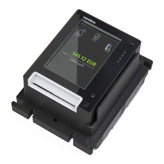
- Page 1 INTEGRATION MANUAL VALINA the next generation compact, convenient, complete product picture – 4.014 x 3.596 •••••• an atos company...
- Page 2 Worldline S.A./N.V. (“Worldline”) The content of this document, including but not limited to trademarks, designs, logos, text, images, is the property of Worldline and is protected by the Belgian Act of 30.06.1994 related to authors’ rights and by the other applicable Acts.
-
Page 3: Table Of Contents
Step 1.Check the gasket positioning ..............9 Step 2.Mount the VALINA in the vending machine ..........9 Step 3.Connect power and communication cables at the back of the VALINA ..9 Step 4.Power up VALINA and fasten cables ............10 Step 5.Install SAM card – optional ..............12 Step 6.Install micro SD card –... - Page 4 VALINA INTEGRATION MANUAL ESD immunity..................... 32 Safety ......................32 VALINA with GSM ..................32 VALINA with WLAN..................32 – empty for double-sided printing – im_valinaTOC.fm...
- Page 5 Figure 4. Power connections – Microfit (left), MDB (right) ........... 10 Figure 5. Cable ties for VALINA...................11 Figure 6. VALINA with TELECOM cover [1] in place ............12 Figure 7. Fitting SAM cards ....................13 Figure 8. Inserting the micro SD card ..................14 Figure 9.
- Page 6 VALINA INTEGRATION MANUAL – empty for double-sided printing – im_valinaLOF.fm...
-
Page 7: About This Book
• approvals and certifications, including applicable environmental regulations Who should use this book • anyone who will be installing a VALINA in a vending machine or other equipment • field and service technicians using the service unit Information from this book may be reused in other documentation such as a user guide. - Page 8 INTEGRATION MANUAL VALINA – empty for double-sided printing – im_vln_about.fm...
-
Page 9: Valina Key Features
PIN, supporting a range of standards including EMV and Mifare. It handles payments by chip card, NFC cards and devices, and magstripe card. The VALINA is PCI 4.x certified, SRED included. It has been designed to provide a complete solution for EMV payments, and can run either newly-developed Android apps or legacy apps (written for the MAPS platform) from Worldline. -
Page 10: Figure 1. Valina - Front View
INTEGRATION MANUAL VALINA Figure 1. VALINA – front view Figure 2. VALINA – back view For more information on connectors, see Power supply, ports and pin-outs, on page 17. – empty for double-sided printing – im_vln_keyFeatures.fm... -
Page 11: Safety
If you notice that any VALINA component blocks, does not fit, or shows any other malfunction, contact your vendor. Do not try to repair or alter it in any way. -
Page 12: Repairs And End-Of-Life
Worldline or an approved service centre. Contact your vendor for information on how to dispose of your VALINA at the end of its life. Do not discard, give away or sell your VALINA as it contains materials that can be recycled and must be treated by a professional party. -
Page 13: Installing Valina
5, before you start installing a VALINA • make sure the contents of the VALINA package are complete and correct Inspect the package for damage, and make sure it contains all the items listed. In case of doubt, or if items are missing or damaged, contact your vendor immediately. -
Page 14: Selecting A Location
Selecting a location The terminal is designed for unattended use both indoors and outdoors. Electrical installations where the VALINA is installed must comply with local and regional codes for office and residential electrical wiring, such as International Electrotechnical Commission (IEC). -
Page 15: Installation Step By Step
Power up VALINA and fasten cables, on page 10 Step 3. Connect power and communication cables at the back of the VALINA There are six numbered interfaces on the back of the VALINA, for connections to external peripherals. unrestricted im_vln_installing.fm document release 0.1... -
Page 16: Step 4.Power Up Valina And Fasten Cables
17. table Step 4. Power up VALINA and fasten cables The VALINA requires an external power supply, using one of these two options: • connector 5 – 12V DC 2A (Microfit connector) • connector 6 – 24-48VDC (MDB connector) The VALINA cannot be powered through any other port. -
Page 17: Figure 5. Cable Ties For Valina
Figure 5. Cable ties for VALINA In normal state, the status LED on the front of the VALINA lights up steadily as soon as you power up the terminal. In tampered state, the device displays a warning message and it is not possible to use the terminal to make a payment. When a warning message... -
Page 18: Step 5.Install Sam Card - Optional
• install any SAM card before installing the optional communications board • install both SAM card and communications board before installing the VALINA in the vending machine. open TELECOM cover Remove the retaining screw of the TELECOM cover (if present) and open the cover. -
Page 19: Step 6.Install Micro Sd Card - Optional
INTEGRATION MANUAL VALINA Figure 7. Fitting SAM cards close all slots Close the SAM holder, and press it down until it engages with an audible click close the TELECOM cover If you will be installing the optional micro SD card or the optional communications board, do not close the TELECOM cover yet If you are using a retaining screw for the cover, use one 8 torx screw (included). -
Page 20: Step 7.Install Communications Board - Optional
Step 7. Install communications board – optional When the VALINA is going to use via 2G/3G or WiFi/Bluetooth, a communications board is required. YONEO communications boards are compatible with the VALINA. For easy access to the communications board, install the board in the VALINA before installing the VALINA in the vending machine. -
Page 21: Figure 9. Inserting Optional Communications Board In Valina
Connect the antenna cable to the connector on the board. Make sure it is an antenna with a card connector and a resistance of 50 Ohm. Do not plug in cables before installing the communication board in the VALINA Fit the SIM in the SIM card holder The SIM card is required for 2G/3G. - Page 22 INTEGRATION MANUAL VALINA – empty for double-sided printing – im_vln_installing.fm...
-
Page 23: Power Supply, Ports And Pin-Outs
This chapter describes the power supply / data connectors on the VALINA. Figure 11. Power supply / data connectors on the VALINA Power supply The VALINA is powered from an external power adaptor through port 5 (TTL) or port 6 (MDB). •... -
Page 24: Usb-B (Device) Interface
USB-B (device) interface The VALINA is fitted with a USB 2.0 Full Speed (up to 480 MBit/sec) device interface, which can be used to connect to ePOS equipment or a PC and to perform keyloading. The necessary USB-driver is included in recent installation packages of most operating systems (Windows, MacOS and Linux). -
Page 25: Rs-232 Interface
[OUT] USB-A (host) interface The VALINA is fitted with a USB 2.0 full speed (up to 480 MBit/sec) host interface, which can be used to connect to a USB stick or other storage device. VALINA cannot be powered through the USB host interface: it always needs an external power supply. -
Page 26: Power Consumption
INTEGRATION MANUAL VALINA Power consumption The VALINA is fitted with a proximity sensor that helps supports smart energy consumption by switching between different states. power consumption Table 7 state details transaction terminal processing transaction by GPRS (backlight on) transaction terminal processing transaction by Ethernet (backlight on) -
Page 27: Jtag/Debug Port
VALINA 6. JTAG/DEBUG port For development and repair purposes, the VALINA is equipped with a JTAG/Debug port, underneath the SAM cover. This port can be used to connect a PACIFIC Debug Interface for debugging and logging purposes. This port can also be used to connect a JTAG Interface for repair and reflash purposes. - Page 28 INTEGRATION MANUAL VALINA Pinout for JTAG/DEBUG port – development terminals only Table 9 description direction description direction JTAG AUTOWR JTAG TSEL(1) JTAG SRSTn IN/OUT DEBUG RXD_B DEBUG TXD_B DEBUG RXD_A DEBUG TXD_A unrestricted last updated 6/6/16 document release 0.1 im_vln_jtag.fm...
-
Page 29: Cleaning
INTEGRATION MANUAL VALINA 7. Cleaning For optimal functioning of your Worldline terminal and accessories, clean them regularly. Disconnect the equipment from the power supply. Clean the equipment with a soft damp cleaning cloth. Clean the display with a soft dry anti-static cleaning cloth. - Page 30 INTEGRATION MANUAL VALINA – empty for double-sided printing – im_vln_cleaning.fm...
-
Page 31: Repairs And End-Of-Life
Worldline or an approved service centre. When a VALINA or any of its accessories is at the end of its life, it must not be simply thrown away, given away or sold on. As terminal vendor, you are responsible for the correct decommissioning of terminals and their components or accessories at their end of life. - Page 32 INTEGRATION MANUAL VALINA – empty for double-sided printing – im_vln_decommission.fm...
-
Page 33: Appendix A. Technical Specifications
INTEGRATION MANUAL VALINA Appendix A. Technical specifications display 3.5”, 320 x 480 pixels, 64K colour, capacitative touchscreen (backlit) communications – on-board Ethernet 10/100 RS-232 communications – optional extensions 2G/3G – GSM, GPRS, EDGE / UMTS, HSDPA Bluetooth/WiFi interfaces Ethernet RS232, to serial peripherals (for example, vending machine controller or printer) -
Page 34: Figure 15. Internal Mounting Details For Valina
For exact measurements, including tolerances, download drawing 3034910003 from the Partner Extranet. integration dimensions (excluding gasket) mounting aperture: 110 * 146 (height/width) clearance: min. 88 (depth) Figure 15. Internal mounting details for VALINA Figure 16. Minimum required space (from EVA Specs) unrestricted last updated 6/6/16 document release 0.1 im_vln_techSpecs.fm... - Page 35 INTEGRATION MANUAL VALINA Optional accessories • communications boards • debug interface • power adaptor input100-240 VAC, 50 – 60 Hz; output 12 VDC 2A unrestricted im_vln_techSpecs.fm document release 0.1 last updated 6/6/16...
-
Page 36: Software
INTEGRATION MANUAL VALINA Environmental conditions operating temperature/humidity -20°C to +70°C (for VALINA without display); 0% to 90% RH non-condensing storage temperature/humidity -25°C to +70°C; storage humidity: 0% to 95% RH flammability rating ANSI/UL 94 V-0 dust-/waterproof rating IP65 protection classification... -
Page 37: Appendix B. Approvals
International Electrotechnical Commission (IEC) 364 parts 1 through 7. The VALINA has been approved/certified in line with international standards including: Approvals/certification • PCI PTS 4.x (SRED and Open Protocols) •... -
Page 38: Esd Immunity
– Section 4: Electrical fast transient / burst immunity test – Section 11: Voltage dips, short interruptions and voltage variations immunity test Safety EN60950-1 Information technology equipment VALINA with GSM • EN301 489 Electromagnetic compatibility and radio spectrum matters (ERM); Electromagnetic compatibility (EMC) standard for radio equipment and services –...
Need help?
Do you have a question about the VALINA and is the answer not in the manual?
Questions and answers