
Related Manuals for Notifier APS-6R


Summary of Contents for Notifier APS-6R
- Page 1 Auxiliary Power Supply APS-6R Instruction Manual Document 50702 4/14/03 Rev: PN 50702:B2 ECN 03-147 www.PDF-Zoo.com firealarmresources.com...
- Page 2 Fire Alarm System Limitations While a fire alarm system may lower insurance rates, it is not a substitute for fire insurance! An automatic fire alarm system—typically made up of Heat detectors do not sense particles of combustion smoke detectors, heat detectors, manual pull stations, and alarm only when heat on their sensors increases at a predetermined rate or reaches a predetermined level.
- Page 3 UniNet™ are trademarks of NIS. NIS™ and Notifier Integrated Systems™ are trademarks and NOTIFIER® is a registered trademark of Fire•Lite Alarms, Inc. Echelon® is a registered trademark and LonWorks™ is a trademark of Echelon Corporation. ARCNET® is a registered trademark of Datapoint Corporation.
- Page 4 Documentation Feedback Your feedback helps us keep our documentation up-to-date and accurate. If you have any comments or suggestions about our online Help or printed manual, you can email us. Please include the following information: • Product name and version number (if applicable) •...
-
Page 5: Table Of Contents
Mounting an APS-6R in a CAB-500 Backbox .........25 Connecting the APS-6R to an MPS-24BRB ........25 Appendix E System 5000, AM2020/AFP-1010 ............26 Mounting an APS-6R in a System 5000, AM2020 or AFP-1010 ..26 Connecting the APS-6R to an MPS-24A ..........26 Connecting the APS-6R to an MPS-24BRB ........26 Appendix F NFS-640 .....................27... - Page 6 PN 50702:B2 4/14/03 www.PDF-Zoo.com firealarmresources.com...
-
Page 7: Section 1 Overview
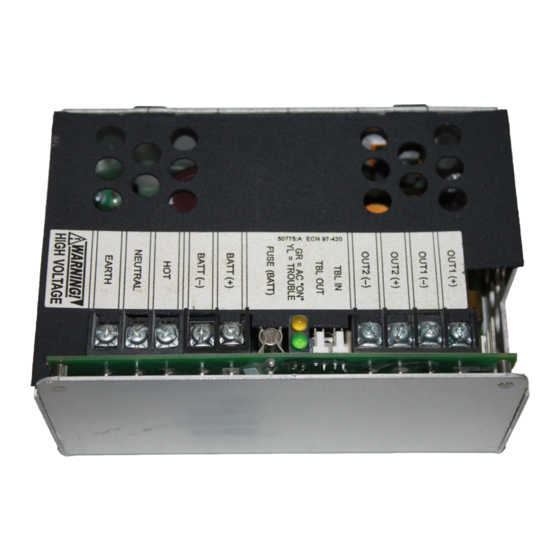
Section 1 Overview Section 1 Overview Introduction This document contains information for installing, servicing, and configuring the APS-6R Auxiliary Power Supply. The table below contains a list of document sources for supplemental information: Control Panels Refer to... Part Number NFS-3030... - Page 8 Section 1 Overview The figures below identify the features of the APS-6R power supply: Trouble In (J4) - Trouble Out (J3) Three 24 VDC output circuits “P” style connectors for internal cabinet One (1) non power-limited connections Two (2) power-limited...
-
Page 9: Specifications
(lead-acid batteries only) 16 mA DC standby current (with AC fail delay operating) Note: The APS-6R is not equipped with a battery charger. Batteries are charged by the system power supply. 24 VDC output power Total 6 A (4 A continuous) Circuit 1 3 A @24 VDC power-limited (+10, –15%) - Page 10 Section 1 Overview Parts Kit A parts kit is included for use in assembling and mounting the APS-6R. It consists of the following items: Quantity Description Part No. AC Power connector cover 02183 #6-32 1.25 in. (10 mm) long, .25 42026 in.
-
Page 11: Section 2 Installation
Section 2 Installation WARNING: Use extreme caution when working with the APS-6R. High voltage and AC line-connected circuits are present. Turn off and remove all power sources. To reduce the risk of electric shock make sure to properly ground the unit. -
Page 12: Mounting In Cab-3/Cab-4 Series Cabinets
If 240 VAC is to be used, cut JP1 jumper at this time. See instructions and high voltage warning on Page 18 in "Configuring the APS-6R". Place the APS-6R onto the mounting studs of the chassis (Figure 4 on page 12). Insert a standoff through each of the printed circuit board mounting holes, threading each standoff to the mounting studs on the chassis. -
Page 13: Wiring The Aps-6R
• Wiring multiple APS-6R power supplies. Field Wiring an APS-6R J1 and J2 can be used in place of TB2 when the APS-6R is powering internal modules (such as an ICM/ICE or XP6-C) with compatible connectors. Output Circuit 3 (J9) can be used as a source of power for the XPIQ Audio Transponder only. - Page 14 EARTH ground terminal on main power supply. If 2 or EARTH more units are connected, secondary units connect to earth ground on the previous APS-6R in the chain. Figure 5 Typical Wiring for an APS-6R PN 50702:B2 4/14/03 www.PDF-Zoo.com firealarmresources.com...
-
Page 15: Connecting Multiple Aps-6R Power Supplies
Section 2 Installation Connecting Multiple APS-6R Power Supplies Typical trouble bus connections for multiple APS-6R power supplies using trouble connectors J3 and J4. Use Cable 71033 for all wiring. See appendix on your system for specific “Trouble Input” connection. Note: J3 and J4 can be interchanged. -
Page 16: Wiring Applications
• Supplying notification appliance power to a control module Connecting the APS-6R to an ICM/ICE Module All four (4) NACs on the ICM are powered from the APS-6R output circuit 2 (J2) and the four (4) NACs on the ICE are powered from circuit 1 (J1). -
Page 17: Supplying Power To A Control Module
SLC loop TENS TENS ONES ONES ADDRESS LOOP LOOP ADDRESS To next device on SLC loop Figure 8 Typical APS-6R Wiring to a Control Module Refer to relevant control module installation documents for specific wiring instructions. PN 50702:B2 4/14/03 www.PDF-Zoo.com firealarmresources.com... -
Page 18: Configuring The Aps-6R
Section 2 Installation Configuring the APS-6R The APS-6R may be configured for the following: • 8-hour delay for reporting loss of AC: cut jumper JP2. • 16-hour delay for reporting loss of AC: cut jumper JP2 and JP3. • 240 VAC operation: See WARNING below. Cut jumper JP1 before applying power. -
Page 19: Servicing The Aps-6R
Section 2 Installation Servicing the APS-6R The only serviceable components on the APS-6R are fuses F1 and F2. If a fuse fails, replace it with a fuse of the same type and rating: • F1 AC protection - 4A, 3 AG •... -
Page 20: Appendix A Afp-200
Mounting an APS-6R to an AFP-200 Backbox The Auxiliary Power Supply is mounted in the bottom of the backbox. Note: If an APS-6R is installed in the backbox, the batteries must be installed in a separate battery box, such as the BB-17. The battery box must be located within 20 feet (6 meters) of the enclosure containing the control panel and all connections must be contained in conduit. -
Page 21: Connecting The Aps-6R To An Afp-200 Power Supply
NEUT • Connect secondary power from TB3 on the APS-6R to terminal block J3 (+ and –) on the AFP-200. • Connect trouble input from J3 on the APS-6R to terminal block J11 on the AFP-200. To battery backup Figure 12 Wiring to AFP-200 Power Supply PN 50702:B2 4/14/03 www.PDF-Zoo.com... -
Page 22: Appendix B Afp-300/Afp-400
Remove plastic cover from APS-6R. If 240 VAC is to be used, cut JP1 jumper at this time. See instructions and high voltage warning in Page 18 in "Configuring the APS-6R". Place the APS-6R onto the mounting studs in the backbox. -
Page 23: Connecting The Aps-6R To An Mps-400
Connecting the APS-6R to an MPS-400 Make the following connections as shown in the figure below. • Connect primary power from TB1 on the APS-6R to MPS-400 terminal block TB1 ( • Connect secondary power from TB3 on the APS-6R to MPS-400 terminal block TB1 (+ and –). -
Page 24: Appendix C Afc-600
TB1 ( NEUTRAL • Connect secondary power from TB3 on the APS-6R to MPS-6 terminal block TB11 (+ and –). • Connect trouble input from J3 on the APS-6R to MPS-6 terminal block J4. NO NC C NO NC C... -
Page 25: Appendix D System 500
) and Pin 4( NEUT • Connect secondary power from TB3 on the APS-6R to MPS-24BRB terminal block TB3, Pin 1(+) and Pin 2(–). • Connect trouble input from J3 on the APS-6R to MPS-24BRB terminal block P4. +24 VRESET COMMON... -
Page 26: Appendix E System 5000, Am2020/Afp-1010
See “Mounting in CAB-3/CAB-4 Series Cabinets” on page 12. Connecting the APS-6R to an MPS-24A Make the following connections as shown in the figure below. • Connect primary power from TB1 on the APS-6R to MPS-24A terminal block TB1, Pin 5( ) and Pin 7( NEUT •... -
Page 27: Appendix F Nfs-640
NEUTRAL and EARTH on the NFS-640. • Connect secondary power from TB3 on the APS-6R to TB1 on the NFS-640, BATT- and BATT+. • Connect trouble input from J3 on the APS-6R to J11 on the NFS-640. To battery backup... -
Page 28: Appendix G Nfs-3030
• Connect secondary power from TB3 BATT(+) and BATT(-)on the APS-6R to TB5 (BAT IN +) and TB4 (BAT OUT-) respectively on the AMPS-24. • Connect trouble input from J3 on the APS-6R to the J5 Trouble bus connection on the CPU-3030. CPU-3030... - Page 29 12 to configure for operation 18 Earth Ground 14 Electrical Specifications 9 AC Loss Delay reporting 16-hour, configuration for 18 Features of the APS-6R 8 8-hour, configuration for 18 Field wiring 13 AC protection fuse 19 Fuses 8 AFC-600 7...
- Page 30 Index Secondary power 14 Self-tapping screw 20 Serviceable components 19 Specifications 9 Standoff 12 Status Indicators 8 System 500 7 System 5000 7 Terminal block cover 13 Trouble Bus connectors 14 Trouble input 21 Warning, High Voltage 11 Wiring 13 XP Series Transponder 7 XP5 Series Transponder 7 XP6-C 13...
- Page 31 Products are date stamped at time of manufacture. The sole and exclusive obligation of NOTIFIER® is to repair or replace, at its option, free of charge for parts and labor, any part which is defective in materials or workmanship under normal use and service.
- Page 32 NOTIFIER is a company. World Headquarters 12 Clintonville Road Northford, CT 06472-1653 USA 203-484-7161 fax 203-484-7118 www.notifier.com www.PDF-Zoo.com firealarmresources.com...
Need help?
Do you have a question about the APS-6R and is the answer not in the manual?
Questions and answers