
Related Manuals for Notifier ACPS-2406


Summary of Contents for Notifier ACPS-2406
- Page 1 Addressable Charger/ Power Supply ACPS-2406 Manual Document 51304 09/02/2003 Rev: PN 51304:B ECN 03-366...
- Page 2 Adequate written records of warning of fires caused by arson, children playing with all inspections should be kept. matches (especially in bedrooms), smoking in bed, and violent explosions (caused by escaping gas, improper storage of flammable materials, etc.). Precau-L-4-2003.fm ACPS-2406 51304:B 09/02/2003...
- Page 3 AWACS™, HARSH™, and VeriFire™ are trademarks, and FlashScan® and VIEW® are registered trademarks of NOTIFIER. Acclimate™, Filtrex™, and Pinnacle™ are trademarks of System Sensor. NION™ is a trademark of NIS. NIS™ and Notifier Integrated Systems™ are trademarks and NOTIFIER® is a registered trademark of Fire•Lite Alarms, Inc.
- Page 4 Brief description of content you think should be improved or corrected • Your suggestion for how to correct/improve documentation Send email messages to: TechPubs@fla-whq.com Please note this email address is for documentation feedback only. If you have any technical issues, please contact Technical Services. ACPS-2406 51304:B 09/02/2003...
-
Page 5: Table Of Contents
Wiring ............... . 13 Section 3 Configuring the ACPS-2406 ....... 16 DIP Switch Configuration . - Page 6 Table of Contents ACPS-2406 PN 51304:B 09/02/2003...
-
Page 7: Section 1 Introduction
7 to 25 AH batteries. Maximum charger current - 1.1 A • Wheelock synchronization devices are compatible with ACPS-2406 software greater than #ACPS1.3, together with Revision L or higher of the ACPS-2406 PC board. (Figure 1.1 on page 10 for revision location.) ACPS-2406 PN 51304:B 09/02/2003... -
Page 8: Installation Standards And Codes
Battery fuse (F2) 15A, 3AB • Line Drop: 2.4 VDC max. to last device 1.3 Installation Standards and Codes The ACPS-2406 complies with the following standards: NFPA 72 National Fire Alarm Code Underwriters Laboratories: • UL 864 Standard for Control Units for Fire Alarm Systems In addition, the installer should be familiar with the following standards: •... -
Page 9: Related Documentation
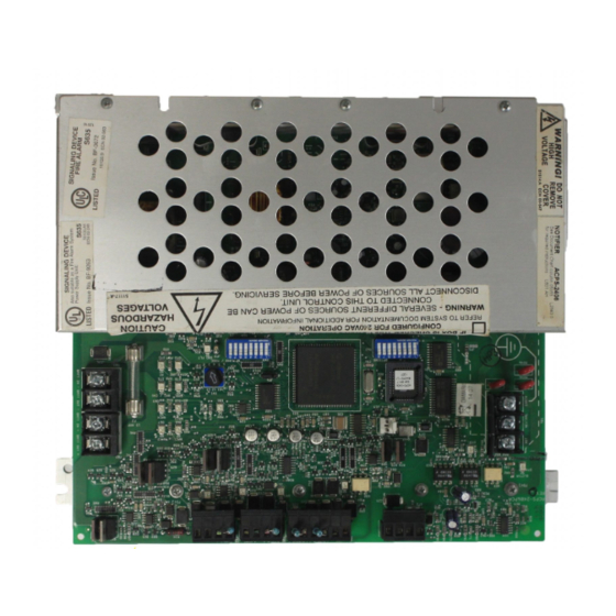
AFAWS 50705 INA Intelligent Network Annunciator 15092 Table 1.1 Related Documentation 1.5 Board Layout The ACPS-2406 board layout is illustrated in Figure 1.1. A second figure below the board layout illustrates the positions of the LEDs. ACPS-2406 PN 51304:B 09/02/2003... - Page 10 OPTIONS 7 6 5 4 3 2 1 7 6 5 4 3 2 UC FAILURE Locations of LED Indicators MONITOR Refer to Table 1.2 for GROUND FAULT Indicator Descriptions Figure 1.1 The ACPS-2406 Board Layout ACPS-2406 PN 51304:B 09/02/2003...
-
Page 11: Led Indicators
Illuminates if the microcontroller fails. Green Illuminates when there is AC power. SLCRXA Green Illuminates when data is transmitted on the SLC. SLCTXA Green Illuminates when data is received from the SLC. Table 1.2 LED Indicators ACPS-2406 PN 51304:B 09/02/2003... -
Page 12: Section 2 Installation
2.1 In a CAB-3 Series Cabinet The ACPS-2406 mounts in the lower left or lower right of CAB-3 Series enclosure. It will also mount in a CHS-6 chassis, requiring the left two of the three chassis spaces, or in a CHS-PS chassis, where it must be installed in the right half. -
Page 13: In A Cab-Ps1 Cabinet
+24 V CO M M + 2 4V R ETUR N T B 8 TB 6 T B5 TB 4 backbox ACPS-2406. The chassis is fastened to the D4 7 D4 0 D 3 2 T B2 D6 6 D6 7... - Page 14 7 AH. Figure 2.6 CAB-PS1 Cabinet: Power-limited Wiring Example TB1 - With all power sources off, connect primary AC power to the “AC” and “NEUT” terminals, and ground the ACPS-2406 at the “EARTH GROUND” terminal. ACPS-2406 PN 51304:B 09/02/2003...
- Page 15 When this output is used for an installation, the maximum load current available at Output #4 (TB6-3 and TB6-4) will be reduced to 2.0 A maximum. To determine battery requirements, refer to Section 5 of this manual. ACPS-2406 PN 51304:B 09/02/2003...
-
Page 16: Section 3 Configuring The Acps-2406
3.1 DIP Switch Configuration Programming at the ACPS-2406 is done by configuring two sets of DIP switches, SW2 and SW3. SW3 is a set of mode selection switches for output circuits one through four, as well as AC Loss, AC Delay, settings for coded NAC patterns, Canadian Trouble Reporting, and Dual Stage operation. - Page 17 ***CAUTION: FOR NON-CODED MASTER/SLAVE OPERATION: when a non-coded signal is supplied to the UZC connections of TB6, the same protocol must also be programmed at the slave ACPS-2406 (using SW2.6 and SW2.7) as programmed at the master ACPS-2406. This will ensure operation of all non-coded outputs of the slave ACPS-2406 should signal loss occur of the synchronization input (UZC connections) at TB6.
-
Page 18: Addressing
Determining Address Consumption An ACPS-2406 can occupy an address block of 5, 6, 8, 9, 12, or 13 addresses on an SLC, depending on the configuration of ACPS-2406 DIP Switches. Table 3.2 through Table 3.7 below detail the DIP Switch/ address consumption relationship. - Page 19 DIP Switch Settings at Left Address ✔ SW3.1 ON or OFF 1.Monitor General ✔ SW3.2 ON or OFF 2. ACPS-2406 Output #1 B + 1 ✔ SW3.3 ON or OFF 3. ACPS-2406 Output #2 B + 2 ✔ SW3.4 ON or OFF 4.
-
Page 20: Setting The Base Address
ACPS-2406 address requirements. All addresses included in the address block must be programmed points at the FACP whether or not the output points are actually used. Note: The lowest base address for the ACPS-2406 is 05. Do not set the FACP addresses 00 through 04 for the ACPS-2406. The Rotary Switch The rotary switch SW1 determines the address decade. - Page 21 ACPS-2406 ACPS-2406 ACPS-2406 ACPS-2406 BASE SWITCH PLUG Addresses Addresses Addresses Addresses Addresses Addresses ADDRESS SETTING POSITION 12 13 5-10 5-12 5-13 5-16 5-17 12 13 120-124 120-125 120-127 120-128 120-131 120-132 Figure 3.2 SLC Address Selection ACPS-2406 PN 51304:B 09/02/2003...
-
Page 22: Panel Programming Requirements
Note: All addresses included in the address block must be programmed points at the FACP whether or not the output points are actually used. Even though some of the 13 possible ACPS-2406 addresses may be skipped, none of the addresses in the FACP address block may be skipped. -
Page 23: Software Type Id Codes
Selecting Dual Stage Mode Dual Stage is selected by setting ACPS-2406 switches SW3.7 to ON and SW3.8 to OFF. ACPS-2406 Dual Stage output circuits must be set to the coded NAC option (See Table 3.1 for settings) Addressing in Dual Stage Mode When the ACPS-2406 is set to Dual Stage, each output circuit uses two control addresses, even if the circuit is not configured for Dual Stage (i.e., not a coded NAC). -
Page 24: Dual Stage Panel Programming
Alert Software Zone Z1 will activate when the Z1 equation is satisfied. ALERT = OR(Z1). A CBE (Control-by-event) in this equation refers to any local CBE that is programmed into this point. It could be a CBE that programs four cross-zoned detectors, for example. ACPS-2406 PN 51304:B 09/02/2003... - Page 25 Z201). The CBE in this equation refers to any local CBE that is programmed into this point. It could be a CBE that programs four or more cross-zoned detectors, for example. Refer to the programming section of the FACP manual for more information on programming. ACPS-2406 PN 51304:B 09/02/2003...
-
Page 26: Section 4 Applications
T B 5 T B 4 DIP Switch Settings Note: The output is power-limited and non-supervised. Use an end-of-line relay to supervise. 3.1 ON 3.2 ON 3.3 ON 3.4 ON Figure 4.2 General Purpose Power Output ACPS-2406 PN 51304:B 09/02/2003... -
Page 27: Style B (Class B) Initiating Device Circuit
4.4 Synchronization The ACPS-2406 provides synchronization to Gentex, SpectrAlert Series and Wheelock strobes and horns. When the ACPS-2406 is set for synchronization with DIP switches SW2.6 and 2.7, these NAC devices will flash and/or sound together The ACPS-2406 can also provide synchronization for bells and horns when used with a UZC-256 Universal Zone Coder if the NAC output is configured for coded signals only. - Page 28 Applications Synchronization Refer to the following figures for application illustrations. Figure 4.4 Supervised Master/Slave Synchronization Connections (Non-Coded) ACPS-2406 PN 51304:B 09/02/2003...
- Page 29 Synchronization Applications Figure 4.5 Supervised Synchronization Wiring Using UZC-256 ACPS-2406 PN 51304:B 09/02/2003...
- Page 30 NAC outputs of another power supply. Use only devices from the same manufacturer in each system. A maximum of five slaves are allowable using this configuration. Figure 4.6 Supervised Daisy Chain Connection (Typical) ACPS-2406 PN 51304:B 09/02/2003...
-
Page 31: Section 5 Power Supply Calculations
Note: Columns A and B of Table 5.1 through Table 5.5 are not battery calculations. They are current calculations to confirm whether the ACPS-2406 can output enough DC current to support its devices during standby and alarm conditions. OUTPUT 1... - Page 32 URRENT URRENT TOTAL TOTAL Note: S for all outputs together cannot exceed 1.0 A. TANDBY URRENT OTAL cannot exceed 2.50 A for any single output. LARM URRENT OTAL Table 5.3 DC Current Draw Calculations, Output 3 ACPS-2406 PN 51304:B 09/02/2003...
- Page 33 TANDBY ALARM UM EACH COLUMN FOR TOTALS URRENT URRENT TOTAL RAW TOTAL Note: S cannot exceed 1.0 A. TANDBY URRENT OTAL cannot exceed 6.0 A. LARM URRENT OTAL Table 5.5 Total ACPS-2406 DC Current Draw Calculations ACPS-2406 PN 51304:B 09/02/2003...
-
Page 34: Battery Calculations
Note: 1. Battery size is limited to 7.0 AH minimum to 25.00 AH maximum using the internal ACPS-2406 battery charger. 2. For battery sizes greater than 25.0 AH, disable internal charger by setting SW3.7 to OFF and use an external battery charger. - Page 35 ACPS-2406 12, 14 Bells, synchronization of Board Layout, ACPS-2406 Brownout detection 7, 11 hex nuts 12, 13 horns Horns, synchronization of CAB-3 Series Cabinets 9, 12, 14 CAB-PS1 Cabinet 9, 13, 14 Canadian Trouble Reporting ACPS-2406 PN 51304:B 09/02/2003...
- Page 36 Panel Addressing Install the snap-on cover Software Type ID Codes Wheelock 7, 27, 28 Power Supervision Relay DIP Switch Configuration Programming, ACPS-2406 - See Configuring the ACPS-2406 Wire size Wiring 13–15 Nonpower-limited Outputs 1 through 4 and UZC-256 connections Rotary Switch...
- Page 37 NOTES: ACPS-2406 PN 51304:B 09/02/2003...
- Page 38 NOTES: ACPS-2406 PN 51304:B 09/02/2003...
- Page 39 Limited Warranty NOTIFIER® warrants its products to be free from defects in materials and workmanship for eighteen (18) months from the date of manufacture, under normal use and service. Products are date stamped at time of manufacture. The sole and exclusive obligation of NOTIFIER® is to...
- Page 40 World Headquarters NOTIFIER is a company. 12 Clintonville Road Northford, CT 06472-1653 USA 203-484-7161 fax 203-484-7118 www.notifier.com...
Need help?
Do you have a question about the ACPS-2406 and is the answer not in the manual?
Questions and answers