Advertisement
Quick Links
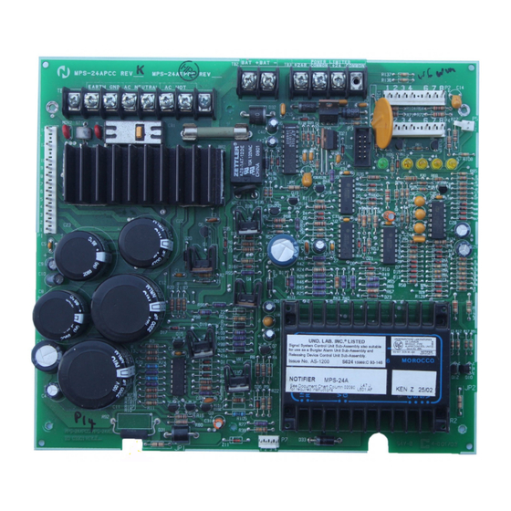
GENERAL
The MPS-24A is the main power supply for the AM2020,
AFP1010, XP Transponder or System 5000 fire alarm control
system. It provides all the necessary internal operating power
plus additional power for operation of external alarm Notifica-
tion Appliance Circuits. A battery charging circuit is included.
FEATURES
• Provides all internal operating power for the system.
• Up to 3.0 A of regulated, filtered alarm notification device
power available, compatible with any listed 24 VDC notifica-
tion appliance or any 24 VDC listed release solenoid.
• Recharges standby batteries up to 55 AH in size.
• Dual-rate charge capability.
• Regulated and filtered four-wire detector power available (de-
pending on the system configuration).
• Trouble LEDs for AC Power Fail, Battery, and Ground Fault
conditions.
• Circuit breaker and automatically-resetting PTC resistors pro-
tect against current overload.
• Power-limited on all external output power.
• High-efficiency DC/DC converter for FACP internal +5 V
power.
• High-efficiency switched regulator for notification appliance
power.
• True battery supervision.
• Optional battery backbox holds 55 AH batteries.
APPLICATIONS
The MPS-24A Main Power Supply provides all of the required
internal system operating power, plus 3.0 A of regulated power
is available for external use.
ELECTRICAL SPECIFICATIONS
Primary input power: 120 volts, 50/60 Hz, 1.8 A maximum
(220 VAC option, model MPS-24AE).
Maximum loading of the 24 volt filtered regulated supply is
6.0 A (used for internal and external power where filtered regu-
lated power is required). Up to 3.0 A may be used to power
Notification Appliance Circuits (NAC) or ACS Series annun-
ciators.
Battery charger: 24-volt float type, capable of charging 9 AH
to 55 AH batteries.
Brown-out and battery monitors.
TROUBLE INDICATORS
• AC POWER FAIL (LED #2) Indicates the loss of AC power,
low AC line or open circuit breaker
• BATTERY (LED #3) Indicates battery failure
• GROUND FAULT (LEDs 4 & 5) indicates a ground fault con-
dition.
NOTIFIER® is a Honeywell company.
This document is not intended to be used for installation purposes. We try to keep our
product information up-to-date and accurate. We cannot cover all specific applications
or anticipate all requirements. All specifications are subject to change without notice.
For more information, contact NOTIFIER. Phone: (203) 484-7161 FAX: (203) 484-7118
12 Clintonville Road, Northford, Connecticut 06472
December 28, 2004
MPS
MPS
MPS
MPS
MPS-24A
Main P
Main Power Supply
Main P
Main P
Main P
ower Supply
ower Supply
ower Supply
ower Supply
Section: Power Supplies
CS118
CS733
S624
California
DENVER
State Fire
Marshal
(System 5000,
7165-0028:141
7165-0028:144
7170-0028:153
7170-0028:154
U.S. Coast Guard
161.002/27/3
(AFP1010
or AM2020)
93/60140 (E2)
(AFP1010,
AM2020)
INSTALLATION
The MPS-24A power supply is installed in the lower bottom-
left corner of the CAB-A3/-A4, CAB-B3/-B4, CAB-C3/-C4, or
CAB-D3/-D4 enclosures. Screw terminals are provided for
Earth Ground; 120 or 220 VAC; Battery positive and negative;
+24 VDC filtered, regulated, resettable power. Plug-in connec-
tors are provided for the Power Ribbon, Power Harness, and
AVPS-24 Supervision connection.
DN-0786 • E-100
-24A
-24A
-24A
-24A
BSA
MEA
578-81-SA
460-92-E
(System 5000)
(AFP1010/
AM2020)
City of
0Z6A4.AY
AFP1010,
(MPS-24A)
AM2020)
0Q1A7.AY
(System 5000)
0W6A2.AY
(AFP1010/
AM2020)
0Y3A0.AY
(XP Transponder)
City of
Chicago
(AFP1010
or AM2020)
(System 5000,
AFP1010,
AM2020)
Made in the U.S.A.
DN-0786 • 12/28/04 — Page 1 of 2
Advertisement

Subscribe to Our Youtube Channel
Related Manuals for Notifier MPS-24A


Summary of Contents for Notifier MPS-24A
- Page 1 Supply ower Supply ower Supply ower Supply Section: Power Supplies GENERAL The MPS-24A is the main power supply for the AM2020, 578-81-SA 460-92-E AFP1010, XP Transponder or System 5000 fire alarm control (System 5000) (AFP1010/ system. It provides all the necessary internal operating power...
- Page 2 PRODUCT LINE INFORMATION MPS-24A Main Power Supply. Includes 3.0 A of filtered, regulated audible/visual power. MPS-24AE Same as MPS-24A, but requires 220 VAC. MPS-TR Optional Main Power Supply Trouble Relay for remote mounting of a stand-alone power supply. UL Listed. Check with factory for additional list- ings and approvals.
Need help?
Do you have a question about the MPS-24A and is the answer not in the manual?
Questions and answers