
Related Manuals for Notifier HLSPS25-XP


Summary of Contents for Notifier HLSPS25-XP
-
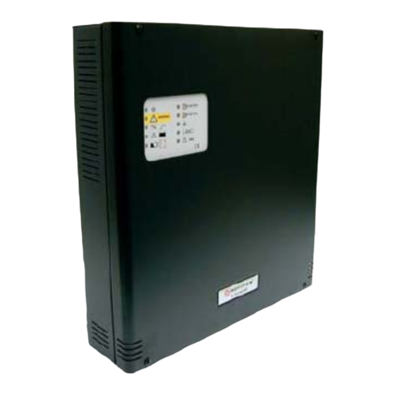
Page 1: Power Supply Unit
Power Supply Unit HLS PS Series HLSPS25-XP and HLSPS50-XP User manual 8 APRIL 2010 MN-DT-1305I_B Information in this document is subject to change without notice... - Page 2 HLS PS25 & HLS PS50 User Manual MN-DT-1305I_B...
-
Page 3: Table Of Contents
HLS PS25 & HLS PS50 User Manual Contents HLS PS Series Installation Checking the HLS PS for damage Pre-installation check list Transient protection Cleaning Back Box HLS PS fixing Functions and indicators HLS PS25 and HLS PS50 characteristics Battery Fault relay Control Unit connections Indicator leds Specification... -
Page 4: Hls Ps Series Installation
HLS PS25 & HLS PS50 User Manual 1. POWER SUPPLIES HLS PS SERIES INSTALLATION The HLS PS Series is easy to install providing the recommended procedures described in this manual are followed. Follow all installation instructions described in this manual. Theses instructions must be understood and followed to avoid damage to the S Series and associated equipment. -
Page 5: Pre-Installation Check List
HLS PS25 & HLS PS50 User Manual 1.2 Pre-installation check list Before selecting the location for the HLS PS Series, DO make sure that: a) The ambient temperature is in the range: -5 ºC to 40 ºC b) The relative humidity is bellow: 93% (non-condensing) c) DO NOT locate the equipment where it is exposed to high levels of moisture. -
Page 6: Back Box Hls Ps Fixing
HLS PS25 & HLS PS50 User Manual 1.5 Back Box HLS PS Series fixing When a suitable location has been found for installing the HLS PS Series, proceed as follows: 1. Hold the back box assembly in the required position against the wall and mark the position of the fixing holes, while ensuring the panel is level. -
Page 7: Functions And Indicators
HLS PS25 & HLS PS50 User Manual 2. HLS PS Functions and indicators FRONT PANEL: FUS BAT FAULT LOW BAT NO BAT BAT CH BAT DIS IN ALARM BAT TEST 321087 MAX. LEGEND: => OUTPUT 1 FAULT => ON => OUTPUT 2 FAULT =>... -
Page 8: Hls Ps25 And Hls Ps50 Characteristics
HLS PS25 & HLS PS50 User Manual 2.1 HLS PS25 / HLS PS50 characteristics These Power Supplies Units are designed to comply with the requirements of EN54-4 in order to provide fire control systems with backup supply. The HLS PS Series operates at 115/230 Vac and 50/60 Hz. Both Power Supply Units, HLS PS25 and HLS PS50, are very similar: they consist of a 2x65W, which means 130W in HLS PS50 and 1x65W in HLS PS25 and a standard module control which supervises the entire... -
Page 9: Battery
HLS PS25 & HLS PS50 User Manual 2.2 Battery DIP SW2 allows selecting the maximum current of battery load, depending on the batteries inside the power supply unit box. With DIP SW2 in ON position (up), 7Amp/h batteries can be charged at 300mA. -
Page 10: Control Unit Connections
HLS PS25 & HLS PS50 User Manual 2.4 Control Unit Connections: The following 4 connectors are placed at the top of the Control Unit: FAULT (C) Fault Relay Common FAULT (NC) Normally Closed Contact FAULT (NO) Normally Open Contact The fault relay may be linked to an analogue input module to report any fault to a third equipment like a FACP (Fire Alarm Control Panel). - Page 11 HLS PS25 & HLS PS50 User Manual The following is placed at the bottom of the Control Unit: IN BAT Batteries (+) IN BAT Batteries (-) TEST The test button allows performing a led test and makes a real test of batteries forcing them to supply current of 1A approx.
-
Page 12: Indicator Leds
HLS PS25 & HLS PS50 User Manual 2.5 Indicator leds: ON Led This led is ON when the Control Unit is powered. Fault Led Yellow led that is ON in case of a Power Supply Fault. When this indication is activated, the C and NC contacts of the fault relay will be closed. - Page 13 HLS PS25 & HLS PS50 User Manual OUTPUT 1 FAULT Led Indicates that the output 1 is not powered. OUTPUT 2 FAULT Led Indicates that the output 2 is not powered. EARTH FAULT Led Indicates an Earth Fault if one of the wirings (+) or (-) is linked to earth.
-
Page 14: Specification
HLS PS25 & HLS PS50 User Manual Specification Dimensions: 377 mm (w) x 408 mm (h) x 92 mm (d). Power Supply Wattage: 130 W (HLSPS50) y 65 W (HLSPS25). The HLSPS50 power supply has a total of 5Amp and 300mA to 600mA of them are dedicated to charge batteries. - Page 15 HLS PS25 & HLS PS50 User Manual MN-DT-1305I_B...
- Page 16 HLS PS25 & HLS PS50 User Manual Honeywell Life Safety Iberia C/Pau Vila 15-19 E-08911 Badalona (Barcelona) Spain Tel.: +34 93 4973960 Fax: +34 93 4658635 www.honeywelllifesafety.es Honeywell Life Safety: Charles Avenue, Burgess Hill, Berliner Straße 91 RH15 9UF West Sussex D-40880 Ratingen Tel.: +44 (0) 1444 230 300 Tel.: +49 2102-700 69-0...
Need help?
Do you have a question about the HLSPS25-XP and is the answer not in the manual?
Questions and answers