Advertisement
Table of Contents
- 1 Table of Contents
- 2 Stoppage of Transfer
- 3 Inspections
- 4 Preparations
- 5 Inspection Operations
- 6 Special Operations
- 7 Specifications
- 8 AL120-L6-150 and LMB6-150
- 9 Problems During Use and Solutions
- 10 When Warning Codes Are Displayed
- 11 When Error Codes Are Displayed
- 12 How to Reset the Circuit Breaker
- 13 After Use of Loader Stop
- Download this manual
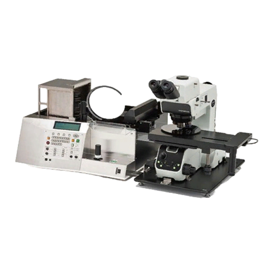
Thank you for purchasing the Olympus AL120 Series Wafer Loader.
In order to fully utilize its performance and secure safety, please read this manual before operation.
Please also keep it at hand during operation as well as for future reference.
Operation Manual
Wafer Loader
AL120-6
AL120-86
Series
Series
AX7833-05
Advertisement
Table of Contents

Related Manuals for Olympus AL120-6 Series


Summary of Contents for Olympus AL120-6 Series
- Page 1 AL120-86 Series Thank you for purchasing the Olympus AL120 Series Wafer Loader. In order to fully utilize its performance and secure safety, please read this manual before operation. Please also keep it at hand during operation as well as for future reference.
- Page 2 This page intentionally left blank.
- Page 3 Introduction Operation/Maintenance Manual i Introduction Option Tray Option AL120-TRY-M61-86 AL120-SLK8 Option Microscope MX61,MX63 Wafer Loader AL120-L6-150 AL120-LMB6-150 AL120-L86 Vacuum Stage AL120-L86-180 AL120-VS6 AL120-LMB86 AL120-VS8 AL120-LMB86-180 Option AL120-LMB8-90 Remote Controller AL120-RC AL120 Series Lineup AL120 series products consist of a model name and an applicable wafer size. Note that only the AL120 series products with the same wafer size can be combined.
- Page 4 Introduction Operation/Maintenance Manual /Precautions The AL120 series consists of a wafer loader, a vacuum stage, and other products. This manual does not cover custom-order specifications or microscopes. To acquire a comprehensive understanding of both your loader and microscope, please refer to your microscope operation manual.
- Page 5 Do not touch wafers during inspection. 11. Undergo maintenance training before attempting to do maintenance on the loader. 12. Consult your nearest OLYMPUS distributor if you need to move the loader. (The loader weight is approximately 44kg.) 13. Down flow that may cause a wafer to shake may cause the wafer transfer operation to be accompanied by physical danger.
- Page 6 S8-0308). Provide adequate space for operating the loader according to your intended use by referring to the installation space and outer dimensions shown on the next page. Installation space AL120-6 Series Unit: mm Stage movable range Working space AL120-86 Series...
- Page 7 Introduction/ Operation/Maintenance Manual Safety Precautions Position of the Center of Gravity AL120-6 Series Position of the center of gravity AL120-86 Series Position of the center of gravity Page...
- Page 8 This equipment is designed in accordance with the SEMI S8 standard. If any other tables are selected, the best performance can not be assured. When selecting the table, please refer to the SEMI S8 standard. Part Dimensions AL120-6 Series Unit: mm Page...
- Page 9 Introduction/ Operation/Maintenance Manual Safety Precautions AL120-86 Series Unit: mm Page...
- Page 10 Introduction Operation/Maintenance Manual /Safety Precautions Earthquake Protection (1) This loader should be secured to prevent it from falling off the table when an earthquake occurs. 1.The fixation method of the microscope *The microscope fixes with an attached bolt. ・M5 hexagon socket head bolt 16 ・M5 spring washer ・M5 machine screw washer 4 points...
- Page 11 Introduction/ Operation/Maintenance Manual Safety Precautions Fixed taps(M8) position dimensions AL 120-6 Series AL 120-86 Series Page...
- Page 12 RESULT IN SEVERE INJURY. KEEP HANDS AND GARMENTS CLEAR OF MOVING PARTS. CONSULT MANUAL FOR PRECAUTIONS DURING MAINTENANCE. Position of warning indication label If this warning label becomes dirty or peels off, contact your nearest OLYMPUS distributor for replacement and servicing. i-10 Page...
- Page 13 Periodically check the loader for wear (a wafer loading arm and deterioration of the drive mechanism), and replace the parts as needed. Contact your nearest OLYMPUS distributor for repair. 1. Never disassemble the loader unnecessarily. This could affect the performance and Caution function of the loader.
- Page 14 1. Confirm the following points before operating the loader. (1) Vacuum supply pressure: -67KPa to -80KPa When there are not a vacuum gauge and a regulator, please contact it to the OLYMPUS distributor. (2) Make sure that there are no wafers or tools inside the wafer loader 2.
- Page 15 Introduction/ Operation/Maintenance Manual Conformity Standards 6. Conformity Standards (1) This equipment is carrying out conformity or evaluation to the following standard. (2) Although this equipment aims at using in the industrial environment, since it may not satisfy a performance when not used by the right operation method, please carry out the proper handling according to this manual.
- Page 16 Introduction Operation/Maintenance Manual /Conformity Standards i-14 Page...
- Page 17 Introduction/ Operation/Maintenance Manual Conformity Standards i-15 Page...
- Page 18 Introduction Operation/Maintenance Manual /Conformity Standards This page intentionally left blank. i-16 Page...
- Page 19 Operation Manual Table of Contents 1 Nomenclature 1-1 Wafer Loader Main Body································································ 1-1 1-2 Operation Panel ···············································································1-2 1-3 Remote Controller (Option) ····························································1-3 1-4 Vacuum Stage ··················································································1-4 2 Outline of Operation Procedures 1 Description of Symbols 2 Operation Procedure 2-1 Procedure before Starting Transfer ···············································2-3 Preparation 1 Turning the Main Switch ON: Main Switch 2 Cassette Setting...
-
Page 20: Table Of Contents
Operation Manual Table of Contents 2-4 Stoppage of Transfer····································································· 2-17 1 Temporarily Stopping the Loader during Inspection: [Pause] Button 2-17 2 Removing a Wafer with Tweezers during Inspection: [Wafer Reject] Button 2-17 3 Unloading a Wafer during Inspection: [Unload] Button 2-18 4 Stopping the Operation Immediately: [Loader Stop] Button 2-18... - Page 21 Operation Manual Table of Contents 4 When a Wafer is on the Vacuum Stage 5-10 Page...
- Page 22 Operation Manual Table of Contents This page intentionally left blank. Page...
- Page 23 Nomenclature Operation/Maintenance Manual 1 Nomenclature Nomenclature 1-1 Wafer Loader Main Body Vacuum tube receptacle AC line receptacle Circuit breakers Stage vacuum Warning label tube connector Cassette guide Cassette table (elevator) A2-arm A1-arm Stage operation permission LED Hand guard Orientation flat alignment sensor Macro (center) table L-arm Liquid crystal panel...
- Page 24 Nomenclature/ Operation/Maintenance Manual Operation Panel 1-2 Operation Panel L type 4-way button Menu buttons Wafer No. Wafer unload selector buttons button Start button Quit button LED display Loader stop button Inspection mode button Wafer alignment position control Option button Supporting function buttons LMB type 4-way button...
- Page 25 Nomenclature /Remote Controller (Option) Operation/Maintenance Manual 1-3 Remote Controller (Option) Remote controller: AL120-RC Registration setting button (Macro) Registration setting button (Micro) Start button Wafer unload button Page...
- Page 26 Nomenclature/ Operation/Maintenance Manual Vacuum Stage 1-4 Vacuum Stage Vacuum stage: AL120-VS6/AL120-VS8 Coarse adjustment grip Wafer rotating knob Y fine travel knob X fine travel knob Clutch lever Vacuum table Stage sensor plate Page...
- Page 27 Operation Manual Outline of Operation Procedure 2 Outline of Operation Procedures 1 Description of Symbols The meanings of the symbols used in Chapter 2 and later are explained below. (1) *: Calls attention to model-specific functions This Operation Manual describes the LMB model that has all the inspection functions. The model names for functions available for certain models are indicated with the symbol *.
- Page 28 Outline of Operation Procedure Operation Manual Operation Flow Controls/Units Reference page section Turn the main switch ON Main switch Set a cassette in place on the cassette table Cassette guide and cassette setting 2-3 ---- Select the type of inspection wafer 4-way button ---- Set the sequence (type of inspection) [Observation] setup buttons...
- Page 29 Operation Manual Outline of Operation Procedure 2-1 Procedure before Starting Transfer Preparation Make sure that there are no wafers in the transfer path or on the vacuum stage. If any wafer is in the transfer path, return the wafer to the cassette using tweezers or the like. 1 Turning the Main Switch ON: Main Switch Turn the main switch At this time the units return to their initial positions if they are in other...
- Page 30 Outline of Operation Procedure Operation Manual 3 Selecting the Type of Inspection Wafer: 4-way button The initial menu appears on the liquid crystal panel 1) To change the type of inspection wafer shown on the liquid crystal panel , press the [M2] <Wafer>...
- Page 31 Operation Manual Outline of Operation Procedure 4 Setting the Sequence (Inspection Type: [Observation] Button * This function is available for the LMB model only. The [Observation] setting buttons are used to specify an inspection sequence. Specify the inspection sequence before initiating inspection. The selected sequence cannot be changed once inspection is started.
- Page 32 Outline of Operation Procedure Operation Manual 5 Setting the Inspection Mode The following three inspection modes can be chosen. Inspection mode button All (100%) inspection Sampling transfer P1 to P10 (Transfer pattern registration) Sampling inspection L1 to L10 (Inspection pattern registration) (1) All (100%) inspection: Press the inspection mode button to turn on the [All] LED (2) Sampling transfer P1 to P10 (Loading pattern registration):...
- Page 33 Operation Manual Outline of Operation Procedure After the setting is completed, press the [M4] <Memory> button. A buzzer sounds to indicate that registration is complete. Press the [M1] <Exit.> Button to exit the setting registration screen. (3) Sampling inspection patterns (L1 to L10) 1) Operation procedure The loader can inspect only a wafer in the specified slot in the cassette according to a specified inspection sequence.
- Page 34 Outline of Operation Procedure Operation Manual If you press the [Wafer No.] button for a wafer for which the inspection sequence is already specified, the LED in the specified inspection sequence button lights up. With the LED turned on this way, you can change the inspection item by pressing the inspection sequence button.
- Page 35 Operation Manual Outline of Operation Procedure 7 Setting the Orientation Flat and Notch Positions on the Microscope: [Wafer alignment] Position Control The orientation flat alignment position can be set to either four different points at intervals of 90 degrees (top, bottom, left and right), or to none.
- Page 36 On the right side as seen facing the cassette opening: [Right] On the left side as seen facing the cassette opening: [Left] * The <Centering unloading> function can be used with the AL120-8 series. It cannot be used with the AL120-6 series. 2-10 Page...
- Page 37 Operation Manual Outline of Operation Procedure 4) Press the [M1]: <Save> button to register the wafer alignment setting. This completes the wafer alignment setting at unloading. To exit without registering the wafer alignment setting (without changing the current setting), press the [M2]: <Cancel>...
- Page 38 Outline of Operation Procedure Operation Manual 2-2 Vacuum Stage 1 How to Move the Vacuum Stage The vacuum stage can be moved by rotating the X fine travel knob and the Y fine travel knob in the lower right section of the stage. One turn of each knob moves the stage approx.
- Page 39 Operation Manual Outline of Operation Procedure 2-3 Start of Transfer 1 Start of Transfer: [Start] Button Press the [Start] button to start inspection. Ref. You can also start inspection using the remote controller. Inspection starts when the stage is set to the wafer transfer position, even if the Microscope operation is not selected.
- Page 40 Outline of Operation Procedure Operation Manual 3 Top Macro Inspection * This function is available for the LMB model only. The movement of the joystick tilts a wafer under Top Macro inspection. The wafer can be tilted up to 30 degrees in any direction.
- Page 41 Operation Manual Outline of Operation Procedure 5 Transferring a Wafer onto the Vacuum Stage To transfer a wafer onto the vacuum stage during the Microscope inspection, move the vacuum stage to the loader. Ref. When the A-arm is lowered completely and the stage is ready to move, the green Stage Operation Permission LED on the stage detection sensor will light up.
- Page 42 Outline of Operation Procedure Operation Manual 6 Temporarily Registering the Inspection Results: [Registration] Button The [Macro] and [Micro] buttons are used to register defective wafers. The registered wafers can be confirmed by pressing the [Recall] button after the inspection is completed. Ref.
-
Page 43: Stoppage Of Transfer
Operation Manual Outline of Operation Procedure 2-4 Stoppage of Transfer 1 Temporarily Stopping the Loader during Inspection: [Pause] Button The [Pause] button stops the wafer in the inspection position and cancels the inspection time setting. The LED in the [Pause] button blinks during a pause. - Page 44 Outline of Operation Procedure Operation Manual 3 Unloading a Wafer during Inspection: [Unload] Button The [Unload] button is used to unload a wafer from the transfer path in the loader (in the Top or Back Macro inspection position) into the cassette and transfer the next wafer. This operation is possible only when two or more types of inspection are selected in the sequence.
-
Page 45: Inspections
Operation Manual Inspections 3 Inspections 3-1 Preparations Make sure that there are no wafers in the transfer path or on the vacuum stage. If there are any wafers in the transfer path, return them to the cassette using tweezers or similar. Turn the main switch ON. - Page 46 Inspections Operation Manual Set the vacuum stage to the wafer transfer position of the main unit. If the vacuum stage has already been set in place, reset it or press the [Start] button........ The first wafer is transferred from the cassette. After the orientation flat alignment (when it is selected), the wafer is transferred onto the vacuum stage.
- Page 47 Operation Manual Inspections 3-2-2 Top Macro Inspection Set a cassette on the cassette table. Make sure that only the [Top Macro] LED in the Observation button is lit........... If the [Top Macro] LED is not lit, press the button to turn on the LED. If LEDs for other types of inspection are lit, turn them off by pressing their buttons.
- Page 48 Inspections Operation Manual 3-2-3 Back Macro Inspection This function is available for the LMB model only. Set a cassette on the cassette table. Make sure that only the [Back Macro] LED in the Observation button is lit. (This step is not required for the L model.) ..............................
- Page 49 Operation Manual Inspections 3-2-4 Back Macro Inspection + 2nd Back Macro Inspection This function is available for the LMB model only. Set a cassette on the cassette table. Select the [Back Macro] and [2nd Back Macro] Observation buttons............When the buttons are selected, the LEDs in the buttons light up. If the [Back Macro] and [2nd Back Macro] LEDs are not lit, press the buttons to turn on the LEDs.
- Page 50 Inspections Operation Manual 3-2-5 Top Macro Inspection + Microscope Inspection This function is available for the LMB model only. Set a cassette to the cassette table. Select the [Top Macro] and [Microscope] Observation buttons..............When the buttons are selected, the LEDs in the buttons light up. If the [Top Macro] and [Microscope] LEDs are not lit, press the buttons to turn on the LEDs.
- Page 51 Operation Manual Inspections Wafers are not transferred onto the microscope if the stage is not in the wafer transfer position at the time of wafer transfer. By setting the vacuum stage to the wafer transfer position during Top Macro inspection, Top Macro observation is terminated before the inspection time is completed.
- Page 52 Inspections Operation Manual 3-2-6 Back Macro Inspection + Microscope Inspection This function is available for the LMB model only. Set a cassette on the cassette table. Select the [Back Macro] and [Microscope] Observation buttons..............When the buttons are selected, the LEDs in the buttons light up. If the [Back Macro] and [Microscope] LEDs are not lit, press the buttons to turn on the LEDs.
- Page 53 Operation Manual Inspections By setting the vacuum stage to the wafer transfer position during Back Macro inspection, the Back Macro inspection is terminated before the inspection time is completed. Microscope inspection is given preference and the wafer is transferred onto the vacuum table. If Microscope inspection is not required, press the [Unload] button.
- Page 54 Inspections Operation Manual 3-2-7 Top Macro Inspection + Back Macro Inspection This function is available for the LMB model only. Set a cassette on the cassette table. Select the [Top Macro] and [Back Macro] Observation buttons..............When the buttons are selected, the LEDs in the buttons light up. If the [Top Macro] and [Back Macro] LEDs are not lit, press the buttons to turn on the LEDs.
- Page 55 Operation Manual Inspections Replace the cassette with the next one, and repeat the procedure from step 1. If [2nd Back Macro] is selected for the inspection sequence, refer to [3-2-4 Back Macro Inspection + 2nd Ref. Back Macro Inspection]. 3-2-8 Microscope Inspection + Top Macro Inspection + Back Macro Inspection + 2nd Back Macro Inspection This function is available for the LMB model only.
- Page 56 Inspections Operation Manual After the specified inspection time has elapsed, the macro table is lowered and the loader proceeds to Back Macro inspection. You can change the wafer tilt position (angle) for observation using the [Back Macro Tilt Angle] button..* Press the [Start] button if the [Inspection Time] control is set to [∞].
-
Page 57: Special Operations
Operation Manual Inspections 3-3 Special Operations 3-3-1 Changing the Wafer Selection Setting You can change the inspection wafer number settings after inspection has started. The wafer numbers can be changed when the [Pause] button is pressed, or while the wafers wait for a start command input when the inspection time is set to ∞. - Page 58 Inspections Operation Manual This page intentionally left blank. 3-14 Page...
-
Page 59: Specifications
Operation Manual Specifications / AL120-L6-150 and LMB6-150 4 Specifications 4-1 AL120-L6-150 and LMB6-150 Item AL120-L6-150 AL120-LMB6-150 1. Transferable Wafer Size SEMI M1-1105 Applicable SEMI Class 1.8: 150 mm mirror-polished single-crystal silicon wafer (with secondary flat) standard Class 1.13: 150 mm mirror-polished single-crystal silicon wafer Applicable wafer 150 ... - Page 60 Operation Manual / AL120-L6-150 and LMB6-150 Item AL120-L6-150 AL120-LMB6-150 Common time setting for the Top Macro and Back Macro inspections 4. Microscope Inspection OLYMPUS MX61 , MX63 Applicable microscope Applicable microscope AL120-VS6 stage Microscopic observation Reflected light observation only method...
- Page 61 Operation Manual Specifications / AL120-L6-150 and LMB6-150 Item AL120-L6-150 AL120-LMB6-150 Wafer protection in case Wafers are held in case of power failure. of power failure 8. Transfer Mechanism Wafer back side vacuum adsorption and mechanical arm transfer Wafer transfer method Wafer removal arm(A1-arm,A2-arm): Conductive Teflon coating Wafer contact area Macro (center) table: Conductive PEEK resin...
- Page 62 Specifications Operation Manual / AL120-L86, LMB86, L86-180, LMB86-180 and LMB-90 4-2 AL120-L86, LMB86, L86-180, LMB86-180 and LMB-90 AL120- AL120- AL120- AL120- AL120- Item L86-180 LMB86 LMB86-180 LMB8-90 1. Transferrable Wafer Size SEMI M1-1105 SEMI M1-1105 Applicable SEMI Class 1.13 , Class 1.9 standard Class 1.9, Class 1.10...
- Page 63 Not available The time can be set in 1 second steps. Inspection time setting Common time setting for the Top Macro and Back Macro inspections 4. Microscope Inspection OLYMPUS MX61 , MX63 Applicable microscope Applicable microscope AL120-VS8 stage Microscopic observation...
- Page 64 Specifications Operation Manual / AL120-L86, LMB86, L86-180, LMB86-180 and LMB-90 AL120- AL120- AL120- AL120- AL120- Item L86-180 LMB86 LMB86-180 LMB8-90 Wafers popping out of a cassette can be detected. Wafer popping Warnings and error The liquid crystal panel shows error codes and their details. An error log can be displayed and obtained.
- Page 65 Operation Manual Specifications / AL120-L86, LMB86, L86-180, LMB86-180 and LMB-90 AL120- AL120- AL120- AL120- AL120- Item L86-180 LMB86 LMB86-180 LMB8-90 2 (IEC60664) Pollution degree Installation category (IEC60664) (Overvoltage category) 12. Required Dimensions and Weight of the Entire System (Wafer loader main unit + Microscope + Microscope fixing tray + Stage) MX61-F,MX-SWETTR,SWH10X,U-D5BDREMC,OB(BD),U-LH100-3,MX-BSH-ESD MX61:...
- Page 66 Specifications Operation Manual / AL120-L86, LMB86, L86-180, LMB86-180 and LMB-90 This page intentionally left blank. Page...
-
Page 67: Problems During Use And Solutions
Operation Manual Troubles and Countermeasures/ When Warning Codes Are Displayed 5 Problems during Use and Solutions 5-1 When Warning Codes Are Displayed While not a malfunction, if the loader determines that there is the W0001 possibility that normal wafer loading operations will be hindered, it issues a warning code on the liquid crystal panel , and halts operations. - Page 68 Troubles and Countermeasures Operation Manual / When Warning Codes Are Displayed Warning Causes and Solutions Code No. Remove the wafer or set the vacuum pressure within the specifications, and then press the [Start] button. Solution [Note] To unload the wafer automatically, refer to 5-6 Automatic Unloading.
-
Page 69: When Error Codes Are Displayed
Take care not to perform automatic unloading without dealing with the cause. Wafers may be damaged. If any similar errors occur during operation, please contact the OLYMPUS distributor for your loader. Please give the distributor the following information: Product name: Serial No.:... - Page 70 Troubles and Countermeasures Operation Manual / When Error Codes Are Displayed Error Codes Error No. Error details Remarks A Vertical movement errors E0101 A Vertical No sensor detection after movement to the upper point U204 U205 E0102 A Vertical No sensor detection after movement to the middle point E0103 A Vertical No sensor detection after movement to the lower point...
- Page 71 Operation Manual Troubles and Countermeasures / When Error Codes Are Displayed Error No. Error details Remarks E0313 A Rotation Overheating of motor driver A Suction error E0314 No detection of the vacuum ON status within the specified time U007 E0315 No detection of the vacuum OFF status within the specified time U007 E0316...
- Page 72 Troubles and Countermeasures Operation Manual / When Error Codes Are Displayed Error No. Error details Remarks (for LMB model only) Back vertical movement errors Macro L Vertical No detection of the upper limit sensor within the specified E0801 U402 time L Vertical No detection of the transfer sensor within the specified E0802...
-
Page 73: How To Reset The Circuit Breaker
Operation Manual Troubles and Countermeasures / How to Reset the Circuit Breaker 5-3 How to Reset the Circuit Breaker Turn the main switch OFF, disconnect the power cord on the back side of the loader, and press the reset button ... - Page 74 Troubles and Countermeasures Operation Manual / Automatic Unloading 5-6 Automatic Unloading When the power is cut off with a wafer left in the transfer path in events E1005 such as an emergency halt, power failure, or occurrence of error, the ...
- Page 75 Operation Manual Troubles and Countermeasures / Automatic Unloading 1 During the Top Macro Inspection When the loader has stopped with a wafer held on the macro table, the vacuum remains on. Unload the wafer according to the following ...
- Page 76 Troubles and Countermeasures Operation Manual / Automatic Unloading 3 When a Wafer is on the A-arm When the loader has stopped with wafers held on the A-arm, the vacuum remains on. Unload the wafer according to the following procedure. When two wafers are held on the A-arm, unload the wafer on the macro table first.
- Page 77 Operation Manual Troubles and Countermeasures / Automatic Unloading The LED in the specified Wafer No. selector button lights up. Press the [Unload] button. After wafer mapping is completed, the wafer is automatically unloaded into the specified slot. 5-11 Page...
- Page 78 Troubles and Countermeasures Operation Manual / Automatic Unloading This page intentionally left blank. 5-12 Page...
- Page 79 This page intentionally left blank.
- Page 80 Woerd Avenue Waltham, MA 02453, U.S.A. OLYMPUS SINGAPORE PTE LTD. 491B River Valley Road,#12-01/04 Valley Point Office Tower, Singapore 248373 OLYMPUS KOREA CO.,LTD. 8F Olympus Tower, 446 Bongeunsa-ro, Gangnam-gu, Seoul, 06153 Korea This publication is printed on clean paper. Printed in Japan...
Need help?
Do you have a question about the AL120-6 Series and is the answer not in the manual?
Questions and answers