Table of Contents
Advertisement
Quick Links
INSTRUCTIONS
U-UCD8
UNIVERSAL CONDENSER
This instruction manual is for the Olympus Universal Condenser Model U-UCD8. To ensure the safety, obtain
optimum performance and to familiarize yourself fully with the use of this condenser, we recommend that you
study this manual thoroughly before operating the microscope. Retain this instruction manual in an easily
accessible place near the work desk for future reference.
A X 7 3 5 3
Advertisement
Table of Contents

Related Manuals for Olympus U-UCD8


Summary of Contents for Olympus U-UCD8
- Page 1 U-UCD8 UNIVERSAL CONDENSER This instruction manual is for the Olympus Universal Condenser Model U-UCD8. To ensure the safety, obtain optimum performance and to familiarize yourself fully with the use of this condenser, we recommend that you study this manual thoroughly before operating the microscope. Retain this instruction manual in an easily accessible place near the work desk for future reference.
- Page 2 Printed on 100% recycled paper with soy ink.
-
Page 3: Table Of Contents
U-UCD8 CONTENTS IMPORTANT — Be sure to read this section for safe use of the equipment. — 1 NOMENCLATURE 2 VARIOUS MICROSCOPY PROCEDURES 6-17 Brightfield Observation (BF) ......................................6-8 Phase Contrast Observation (PH) ..................................8-9 Nomarski Differential Interference Contrast Observation (DIC) ................. 10-14 Darkfield Observation (DF) ...................................... -
Page 4: Important - Be Sure To Read This Section For Safe Use Of The Equipment
IMPORTANT This product is a universal condenser applicable in advanced research applications based on complex combination of observation methods. By simply exchanging the optical elements, the condenser can be used in a variety of microscopy under transmitted light, including the brightfield, darkfield, phase contrast, Nomarski differential interference contrast (DIC) and simplified polarized light observations. - Page 5 U-UCD8 Maintenance and Storage 1. Clean all glass components by wiping gently with gauze. To remove fingerprints or oil smudges, wipe with gauze slightly moistened with a mixture of ether (70%) and alcohol (30%). Since solvents such as ether and alcohol are highly flammable, they must be handled carefully. Be sure to keep these chemicals away from open flames or potential sources of electrical sparks —...
-
Page 6: Nomenclature
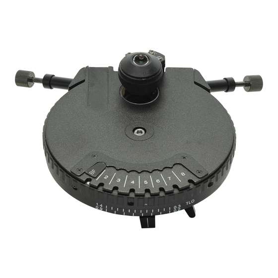
NOMENCLATURE (Note) : Used when the U-UCD8 is combined with the IX/IX2 Universal Condenser Series or BX51WI microscope. (Page 33) Top lens (Page 21) The standard, dry type top lens (U-TLD) can Optical element index plate be exchanged with the oil immersion type mounting position (Page 29) top lens (U-TLO). - Page 7 U-UCD8 Optical element centering screws Polarizer clamping knob (Pages 9 & 15) Polarizer rotation knob (Pages 12 & 17) Top lens swing-out lever Aperture iris diaphragm lever (Page 7) Clamping knob Accommodation position. 1- plate (Page 14) Polarizer handling knob...
- Page 8 Optical Elements (For the applicable objectives, see pages 22 - 27.) Phase Contrast Ring (Small) DIC Prism (Small) DIC Prism (Large) Number sticker U-PH1S U-DIC10S Other DIC rings than the U-PH2S U-DP10S U-DIC10S/U-DP10S. Indication plate sheet U-PH3S Darkfield ring Phase contrast ring (Large) U-DFA U-PH3...
-
Page 9: Various Microscopy Procedures
U-UCD8 VARIOUS MICROSCOPY PROCEDURES }If the top lens and optical elements have not been assembled yet, first read Chapter 5, “ASSEMBLY” (pages 21 to 30). 2-1 Brightfield Observation (BF) Applicable objective power Power 1.25X 100X Brightfield (BF) – ¦ ¦... - Page 10 7. Reduce the field iris diaphragm opening until its image circumscribes the field of view. 8. Adjust the aperture iris diaphragm. # If the slide glass is thicker than 1.2 to 1.4 mm, the image of the field diaphragm may remain fuzzy. When performing photomicrography, use a side glass with a thickness between 0.2 and 1.2 mm whenever possible.
-
Page 11: Phase Contrast Observation (Ph)
U-UCD8 · As microscopic specimens are usually low in contrast, reduc- ing the diaphragm opening to 70% or 80% of the objective’s N.A. will generally provide an image of acceptable quality. To check the opening, after completing focus adjustment, remove one of the eyepieces and look into the empty eyepiece sleeve. - Page 12 3. Mount the phase contrast objective to be used in the revolving nosepiece and rotate the nosepiece to swing in the objective. 4. Open the aperture iris diaphragm. # When the aperture iris diaphragm is stopped down, flare may occur at the center. 5.
-
Page 13: Nomarski Differential Interference Contrast Observation (Dic)
U-UCD8 2-3 Nomarski Differential Interference Contrast Observation (DIC) Applicable objective power Power 100X ¦ ¦ ¦ ¦ ¦ Nomarski Differential Interference Contrast (DIC) Top lens IN To perform Nomarski DIC observation, the transmitted light DIC slider and an analyzer (U-ANT or U-AN) are required. - Page 14 Installation using U-DICTS, U-DICTHC or U-DICTHR Analyzer (U-AN) Clamping knob** To be inserted into the Prism position switch lever mount on the vertical illuminator Pushed in: BFP1 Pulled out: NORMAL DIC-compatible revolving nosepiece Analyzer for transmitted (U-D6RE, U-D5BDRE, etc.) light* (U-ANT) To be inserted into the dummy Transmitted light DIC slider slider of the U-KPA simplified...
- Page 15 U-UCD8 1. Adjust the polarizer in accordance with the following procedure. @Engage the transmitted light DIC prism slider in the light path and tighten the clamping knob. Then engage the reflected light analyzer (U-ANT or U-AN) in the light path.
- Page 16 When using U-DICT with analyzer other than U-ANT a) Disengage the DIC slider from the light path. b) Push in the polarizer handling knob to insert the polarizer into the light path. c) Rotate the polarizer rotation knob to the position where the field of view is perfectly dark, then tighten the polarizer clamping knob.
- Page 17 U-UCD8 @Rotate the prism control knob of the DIC slider to obtain the background interference color that can achieve the maximum contrast according to the specimen under observation. U-DICT: The background interference color is continuously variable between sensitive gray and sensitive magenta.
-
Page 18: Darkfield Observation (Df)
2-4 Darkfield Observation (DF) Applicable objective power Power 100X Darkfield (DF) ¦* ¦** ¦** ¦** ¦** Top lens (U-TLD) IN (U-TLO cannot be used.) * With the superwide-field observation (FN 26.5), flare may be observed in the peripheral areas of the field of view. -
Page 19: Simple Polarized Light Observation (Kpo)
U-UCD8 8. Move the condenser up and down until uniform darkfield illumination is attained. 9. Open the field iris diaphragm to the extend that even brightness is attained. # Keep eyes away from the eyepiece while changing the objective during darkfield observation or changing from darkfield observation to another observation mode. - Page 20 4. Rotate the polarizer rotation knob to achieve a perfectly black field and then tighten the clamping knob. }The “crossed Nicol” (perfectly dark) position is located near the 0 position index. 5. Place the specimen on the stage and move the stage up and down to bring the specimen into focus. 6.
-
Page 21: Troubleshooting Guide
Under certain conditions, performance of the unit may be adversely affected by factors other than defects. If problems occur, please review the following list and take remedial action as needed. If you cannot solve the problem after checking the entire list, please contact your local Olympus representative for assis- tance. - Page 22 Problem Cause Remedy Page e. Polarizing performance is. Polarizer is not inserted in light path. Engage polarizer in light path. insufficient. Analyzer is not inserted in light path. Engage analyzer in light path. –– Optical element is engaged. Engage empty position by rotating turret. ––...
-
Page 23: Specifications
U-UCD8 SPECIFICATIONS Specifications Item Dry type top lens (U-TLD) Immersion type top lens (U-TLO) Applicable microscope BX40, BX50, BX60, BX41, BX51, BX52, etc. Transmitted light (brightfield, darkfield, phase contrast, Transmitted light (brightfield, DIC) Applicable microscopy DIC, polarizer light) Type Achromat-Aplanat, swing-out type top lens (Top lens interchangeable) Numerical Aperture (N.A.) -
Page 24: Assembly
ASSEMBLY 5-1 Mounting the Top Lens }Mount the dry type top lens (U-TLD) or oil immersion type top lens (U-TLO) depending on your observation requirement. # When replacing the top lens, make sure not to apply ex- cessive force to the top lens arm. Mount the top lens @ by rotating it clockwise. -
Page 25: Mounting The Optical Elements
U-UCD8 5-2 Mounting the Optical Elements Optical Element Mounting Positions (Fig. 6) 1,3: The U-DIC10S or U-DP10S optical element can be mounted. 2: Any of the U-PH1S, U-PH2S and U-PH3S can be mounted. 4,8: The U-DFA and U-PH3 can be mounted. When not in use, DIC optical elements can be mounted. - Page 26 Optical Elements and Compatible Objectives Phase contrast (PH) and darkfield (DF) observations: Using U-TLD top lens UIS2 Series Observation Optical Element Applicable Objectives U-PH1S PlanN10XPh, PlanN20XPh, UPlanFLN10XPh, UPlanFLN20XPh U-PH2S PlanN40XPh, UPlanFLN40XPh PlanN100XOPh, UPlanFLN60XOPh, UPlanFLN100XOPh U-PH3S, U-PH3 PlanN10X, PlanN20X, PlanN40X, PlanN50XOI, UPlanFLN10X, UPlanFLN20X, UPlanFLN60XOI, U-DFA UPlanFLN100XOI, UPlanSApo10X UIS Series...
- Page 27 U-UCD8 UIS2 Series DIC observation (U-DICT/DICTS) (Note) For the U-DICTHC and U-DICTHR, see next page. DIC Slider U-DICT Shift type U-DICTS Top Lens U-TLD U-TLO U-TLD U-TLO UPlanFLN U-DIC10, U-DIC10S U-DIC10, U-DIC10S U-DIC20 U-ODIC20 U-DIC20 U-ODIC20 U-DIC40 U-ODIC40 U-DIC40 U-ODIC40...
- Page 28 DIC observation (U-DICTHC/DICTHR) High-contrast type High-resolution type DIC Slider U-DICTHC U-DICTHR U-TLO Top Lens U-TLD U-TLD (for VEC/DIC) UPlanFLN U-DIC10HC U-DIC10HR U-DIC20HC U-DIC20HR U-DIC40HC U-DIC40HR 40XO U-DIC40HC U-DIC40HR U-DIC60HC U-DIC60HR U-ODIC60HR 60XOI 100XO U-DIC100HC U-DIC100HR U-ODIC100HR 100XOI UPlanSApo U-DIC10HC U-DIC10HR U-DIC20HC U-DIC20HR U-DIC40HC...
- Page 29 U-UCD8 UIS Series (Note) Usable regardless of the model number (3, 2 or none). DIC observation (U-DICT/DICTS) (Note) For the U-DICTHC and U-DICTHR, see next page. DIC Slider U-DICT Shift type U-DICTS Top Lens U-TLD U-TLO U-TLD U-TLO UPlanFI U-DP10, U-DP10S...
- Page 30 DIC observation (U-DICTHC/DICTHR) High-contrast type High-resolution type DIC Slider U-DICTHC U-DICTHR U-TLO Top Lens U-TLD U-TLD (for VEC/DIC) UPlanFI U-DP10HR U-DP20HC U-DP20HR U-DP40HC U-DP40HR 60XOI3 U-DPO60HC U-DPO60HR U-ODPO60HR 100XO3 U-DP100HC U-DP100HR U-ODP100HR 100XOI3 UPlanApo U-DP10HR 10XW3 10XO3 U-DPA20HR 20XO3 U-DPA40HR 60XW3 U-DPO60HC U-DPO60HR...
- Page 31 U-UCD8 Mounting the Phase Contrast Ring (Figs. 7 & 8) or Darkfield Ring ³ 1. Using the Allen screwdriver provided with the microscope, loosen the turret cover clamping screw @ and remove the turret cover ². ² # When removing the turret cover, care should be taken to prevent damage to the top lens and the dust protective glass in the turret cover.
- Page 32 }The optical element index plate (Magnet absorption) is pro- vided with the condenser. 6. Align the optical element mount position No. and the index plate attaching position No. ƒ on the turret cover, then attach ƒ the index plate …. …...
- Page 33 U-UCD8 Mounting the DIC Prism (Figs. 10 & 11) }The mounting method is variable between the mounting po- sitions with centering mechanism (1, 3, 4, 8) and those without centering mechanism (5, 6, 7). When the mounting position is 1, 3, 4 or 8: The DIC prism can be mounted in the same way as a phase contrast ring.
-
Page 34: Mounting The Condenser
5-3 Mounting the Condenser (Fig. 12) Also refer to the instruction manual for the microscope in use. Attach the condenser to the condenser holder in accordance ² with the following procedure. 1. Rotate the coarse adjustment knob @ to raise the stage to a height where it does not hit the objective. -
Page 35: Centering The Condenser
U-UCD8 5-4 Centering the Condenser (Fig. 13) Also refer to the instruction manual for the microscope in use. Center the condenser in accordance with the following pro- Field iris diaphragm image cedure. Eyepiece field of view 1. Rotate the turret to select the BF brightfield observation light path (with no optical element engaged). -
Page 36: Indication Using Number Stickers
5-5 Indication Using Number Stickers (Figs. 14 & 15) # To improve the adhesive strength of the number sticker attaching grooves, remove stain and oil using the ether-alcohol mixture. 1. Fig. 14 shows the relationship between the number sticker attaching grooves (1 to 8) and the turret. Attach the number stickers to the designated grooves. - Page 37 MEMO...
- Page 38 MEMO...
- Page 40 Shinjuku Monolith, 3-1, Nishi Shinjuku 2-chome, Shinjuku-ku, Tokyo, Japan Postfach 10 49 08, 20034, Hamburg, Germany 2 Corporate Center Drive, Melville, NY 11747-3157, U.S.A. 491B River Valley Road, #12-01/04 Valley Point Office Tower, Singapore 248373 2-8 Honduras Street, London EC1Y OTX, United Kingdom. 31 Gilby Road, Mt.
Need help?
Do you have a question about the U-UCD8 and is the answer not in the manual?
Questions and answers