Table of Contents
Advertisement
Quick Links
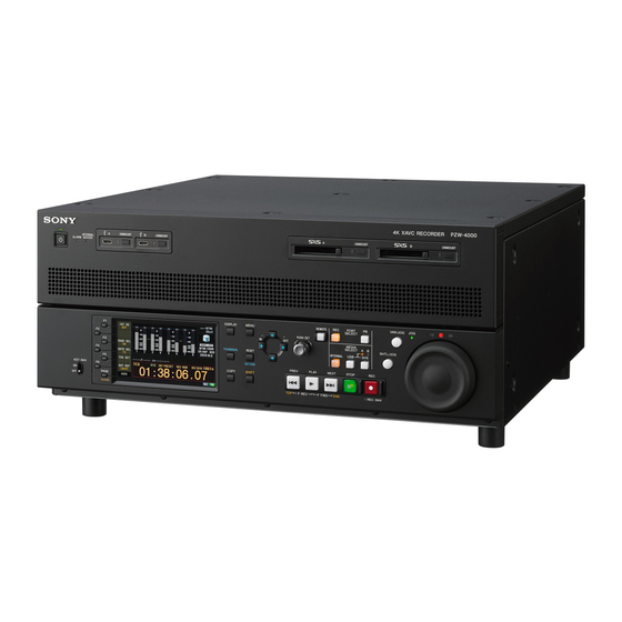
4K XAVC RECORDER
PZW-4000
INTERNAL MEMORY ARRAY (2TB)
PZWK-4020
10GBE NIC OPTICAL
PZWK-4030F
利用条件:
① 本情報はソニー製品の販売,設置,設定,使用の目的でのみご利用ください。かかる
目的以外での利用を禁止します。
② 著作者の事前の書面による許可なく,本情報の全部または一部の複写,複製,転載,
改変,翻訳,送信等を禁止します。
情報改訂:
本情報は,当社の裁量により,予告なく変更されることがあります。ご使用される場合,
本情報が最新の情報であることを確認のうえ,ご使用ください。
Conditions of Use:
(1) Please use this information only for the purpose of sales, installation, configuration,
and use of Sony products. Using this information for any purpose other than the purpose
described foregoing is forbidden.
(2) Do not copy, replicate, reproduce, alter, translate, transmit, sell, lease, or distribute this
information in whole or in part without the prior written permission of the author.
Revision of Information:
This information may be changed or updated at any time without any prior notice. Please
confirm that this information is up-to-date before using it.
SERVICE MANUAL
1st Edition (Revised 3)
Advertisement
Table of Contents

Related Manuals for Sony PZW-4000


Summary of Contents for Sony PZW-4000
- Page 1 Conditions of Use: (1) Please use this information only for the purpose of sales, installation, configuration, and use of Sony products. Using this information for any purpose other than the purpose described foregoing is forbidden. (2) Do not copy, replicate, reproduce, alter, translate, transmit, sell, lease, or distribute this information in whole or in part without the prior written permission of the author.
- Page 2 警告 このマニュアルは,サービス専用です。 お客様が,このマニュアルに記載された設置や保守,点検,修理などを行うと感電や火災, 人身事故につながることがあります。 危険をさけるため,サービストレーニングを受けた技術者のみご使用ください。 WARNING This manual is intended for qualified service personnel only. To reduce the risk of electric shock, fire or injury, do not perform any servicing other than that contained in the operating instructions unless you are qualified to do so. Refer all servicing to qualified service personnel.
- Page 3 設置時には,通気やサービス性を考慮して設置スペース 本機をラックに設置するとき を確保してください。 熱の適切な排気 ・ 発散を得るために,ラックと本機の間 には,以下の空間を確保してください。 . ファンの排気部や通気孔(左側面および右側面)をふ ・左右両側面 4 cm 以上 さがない。 ・後面 10 cm 以上 . 通気のために,セット周辺に空間をあける。 . 作業エリアを確保するため,セット後方は,10 cm 以 上の空間をあける。 Attention-when the product is installed in Rack: 机上などの平面に設置する場合は,左側面および右側面 は 4 cm 以上の空間をそれぞれ確保してください。 1. Prevention against overloading of branch circuit ただし,セット上部はサービス性を考慮し...
- Page 4 注意 FÖRSIKTIGHET! 指定以外の電池に交換すると,破裂する危険があり Fara för explosion vid felaktigt placerat batteri. ます。 Byt endast mot samma eller likvärdig typ av batteri, 必ず指定の電池に交換してください。 enligt tillverkarens rekommendationer. 使用済みの電池は,国または地域の法令に従って När du kasserar batteriet ska du följa rådande lagar 処理してください。 för regionen eller landet. CAUTION PAS PÅ...
-
Page 5: Table Of Contents
Table of Contents Section 1 Service Overview.................................. 4 1-1. Location of Main Parts ................................. 4 1-1-1. Location of Printed Circuit Boards ............................4 1-1-2. Location of Main Mechanical Parts ............................5 1-2. Function and Location of Sensors ..............................6 1-3. Functions of Onboard Switches and LED Indicators ........................7 1-3-1. - Page 6 4-4-5. OPTION SETTING (M14) ..............................62 4-4-6. HOUR METER RESET (M1E) ............................63 4-4-7. ADJUST (M1F) ................................... 64 4-5. SDI CONFIG (M2) ..................................66 4-5-1. P1 SDI1-4 (M21) ................................. 66 4-5-2. P1 SDI9 (M22) ..................................66 4-5-3. P2 SDI5-8 (M23) ................................. 67 4-5-4.
- Page 7 7-12. AU-383 Board ..................................122 7-13. AU-382 Board ..................................123 7-14. HN-431 Board ..................................125 7-15. MB-1247 Board ..................................126 7-16. SW-1737B Board ..................................133 7-17. EC-92 Board ................................... 134 7-18. DIF-267 Board ..................................136 7-19. FP-166B Board ..................................138 7-20.
-
Page 8: Section 1 Service Overview
Section 1 Service Overview 1-1. Location of Main Parts 1-1-1. Location of Printed Circuit Boards Location No. Board name Circuit function AU-382 AES/EBU I/O board AU-383 Analog audio I/O board CN-3989 Bridge board DIF-267 SxS process IF board EC-92 SxS connector board FP-166 Control panel board (LCD/SW/JOG/SHUTTLE) HN-431... -
Page 9: Location Of Main Mechanical Parts
1-1-2. Location of Main Mechanical Parts Switching regulator DC fan (CPU/MB) DC fan (SSD) DC fan (HPR) -
Page 10: Function And Location Of Sensors
1-2. Function and Location of Sensors Location No. Part Name Ref. No. Function Temperature sensor IC2503 Controls the temperature alarm Temperature sensor IC1504 Controls the temperature alarm HPR-66 Board/Side A MB-1247 Board/Side A... -
Page 11: Functions Of Onboard Switches And Led Indicators
1-3. Functions of Onboard Switches and LED Indicators 1-3-1. Description of Onboard LED Indicators AU-383 Board S100 S200 S1200 S1100 AU-383 Board/Side A REF No. Name Description Factory Setting ‒ ‒ S100 Turns ON/OFF the 600-ohm termination resistor for the CH1 analog input. - Page 12 HPR-67 Board S2000 HPR-67 Board/Side B Note Do not change the settings of the switches described as “Factory use”. REF No. Name Description Factory Setting ‒ S2000 Not used Factory use OFF: Normal operation ON: Forced normal startup OFF: Normal operation ON: Forced recovery startup OFF: Normal operation ON: Serial number writable...
- Page 13 KY-656/KY-795 Board S801 S501 KY-656/KY-795 Board/Side A Note Do not change the settings of the switches described as “Factory use”. REF No. Name Description Factory Setting ‒ S501 OFF: Normal operation ON: Disables accesses to the Maintenance mode. OFF: Normal operation ON: Forced recovery startup Factory use Factory use...
- Page 14 MB-1247 Board S1507 S1504 S1503 MB-1247 Board/Side A Note Do not change the settings of the switches described as “Factory use”. REF No. Name Description Factory Setting ‒ ‒ S1501 POWER_SW Factory use ‒ ‒ S1502 SYS_RESET Factory use ‒ S1503 OFF: Normal operation ON: When the onboard device firmware is updated...
-
Page 15: Description Of Onboard Led Indicators
1-3-2. Description of Onboard LED Indicators AU-382 Board D512 AU-382 Board/Side A REF No. Name Color Description Normal State ‒ D512 Green Lights while voltage +3.3 V is supplied. Green AU-383 Board D805 D712 D713 AU-383 Board/Side A REF No. Name Color Description... - Page 16 DIF-267 Board D100 DIF-267 Board/Side A REF No. Name Color Description Normal State ‒ D100 Green Lights while voltage +12 V is supplied. EC-92 Board EC-92 Board/Side A REF No. Name Color Description Normal State ‒ D101 Green/Orange Lights green while the SxS device is mounted. Lights orange during write access to the SxS device.
- Page 17 HPR-66 Board D1902 D1901 D1903 D1900 D600 D300 D1601 D1600 D1602 D1603 HPR-66 Board/Side B REF No. Name Color Description Normal State D300 INIT DONE Green Lights momentarily when power is turned on, and then goes out immediately. D600 CONFIG DONE Lights red during configuration, and then goes out after configuration.
- Page 18 HPR-67 Board D900 HPR-67 Board/Side B REF No. Name Color Description Normal State D900 SUBV CFG Lights red during configuration, and then goes out after configuration. D1200 SUBA CFG Lights red during configuration, and then goes out after configuration. D1600 DSP0 Green DSP0...
- Page 19 KY-656/KY-795 Board D504 D503 D502 D501 KY-656/KY-795 Board/Side A REF No. Name Color Description Normal State ‒ D501 Green CPU LED Blinks ‒ D502 Green Light while recovery boot is in progress. ‒ D503 Green Not used ‒ D504 Green CPU LED Blinks...
- Page 20 MB-1247 Board D1501 D1515 D1511 IC1504 D1514 D1508 D4510 MB-1247 Board/Side A REF No. Name Color Description Normal State D1501 FAN_IC1_ALERT Lights during FAN1 error. D1502 FAN_IC2_ALERT Lights during FAN2 error. D1503 FAN_IC3_ALERT Lights during FAN3 error. D1518 FAN_IC4_ALERT Lights during FAN4 error. D1505 TMP_IC1_ALERT Lights when ambient temperature of IC1504 is abnormal.
- Page 21 REF No. Name Color Description Normal State D2513 SSD1_x4 Green Lights during PCIeSW to Main SSD link. Green D2514 SSD2_x4 Green Lights during PCIeSW to Opt#1 SSD link. D2515 SSD3_x4 Green Lights during PCIeSW to Opt#2 SSD link. D2516 SSD4_x4 Green Lights during PCIeSW to Opt#3 SSD link.
-
Page 22: Circuit Protection Parts
1-4. Circuit Protection Parts 1-4-1. Circuit Protection Element This unit is equipped with positive-characteristic thermistors (power thermistors) as circuit protection elements. The positive-characteristic thermistor limits the electric current flowing through the circuit as the internal resistance increases when an excessive current flows or when the ambient temperature increases. If the positive-characteristic thermistor works, turn off the main power of the unit and inspect the internal circuit of the unit. -
Page 23: Replacing Fuses
1-4-2. Replacing Fuses WARNING Fuses are essential parts for safe operation. Be sure to use the parts specified in this manual. Replacing a fuse with an unspecified one may cause fire or electric shock. CAUTION If the fuse is replaced while the main power is kept on, this may cause electric shock. Before replacing any fuse, not only remove this unit from a camera but also remove the battery pack and disconnect the cable that is connected to the AC IN connector. -
Page 24: Disconnecting/Connecting Fine-Wire Coaxial Cable
1-7. Disconnecting/Connecting Fine-Wire Coaxial Cable Note • Be very careful when handling the fine-wire coaxial cable so that fine wires are not disconnected. • When disconnecting the fine-wire coaxial cable, be sure to hold the connector. Do not attempt to pull the cable. •... - Page 25 Type B Disconnecting Hold both sides of the fine-wire coaxial cable connector, and pull the connector straight to disconnect it. Both sides of connector Hold the connector to disconnect. Correct Do not attempt to disconnect by Fine-wire coaxial cable Wrong pulling the cable.
-
Page 26: Power Cord
1-8. Power Cord This unit does not come with a power cord. To get a power cord, please contact your local Sony Sales Office/Service Center. WARNING • Use the approved Power Cord (3-core mains lead)/Appliance Connector/Plug with earthing-contacts that conforms to the safety regulations of each country if applicable. -
Page 27: Section 2 Error Messages
Section 2 Error Messages 2-1. Error Message Overview This unit has a self-diagnosis function to detect internal errors. When the unit detects an error, its error code and information are displayed on the following display units. (XX-XXX shows an error code.) •... -
Page 28: Error 91
2-2-2. Error 91 When interface (between CPU and peripheral devices) errors are detected, the following error codes are displayed. IT CPU: COM Express CPU Module/MB-1247 board IO CPU: IC1901/HPR-67 board FP CPU: IC1/KY-656/KY-795 board Main code Sub code Description Communication between IT CPU and FP CPU is interrupted (detected by IT CPU). IT CPU detects a memory module (SO-DIMM on the CPU Module) error. -
Page 29: Alarms (Warning)
2-3. Alarms (Warning) An alarm (warning message) appears in the status display area when an operation is attempted which is inappropriate for the settings on this unit or the state of a media.Both the alarm message and the action to take to resolve the problem appear on the video monitor screen connected to the 3G-SDI MONITOR OUTPUT connector. -
Page 30: When A Memory Card Is Inserted
2-3-2. When a Memory Card is Inserted Alarm message in Alarm message in video monitor screen Description/action status display area W40-021 Over DUR!(SxS-A) EXCESSIVE DURATION IS IN SxS-A. A clip with a duration that exceeds 12 hours is recorded on a memory card. W40-022 Over DUR!(SxS-B) EXCESSIVE DURATION IS IN SxS-B. -
Page 31: During Front Panel Operation
2-3-3. During Front Panel Operation Alarm message in Alarm message in video monitor screen Description/action status display area — KEY INHI.! Displayed when the KEY INHI switch is “ON”. Set the KEY INHI switch to “OFF”. — Not Open Clip! Displayed when a clip operation is attempted with no clip selected. -
Page 32: During Recording Operations
2-3-4. During Recording Operations Alarm message in Alarm message in video monitor screen Description/action status display area W10-030 Input Sig! VIDEO INPUT SIGNAL DOES NOT A signal that does not match the system frequency MATCH SYSTEM FREQUENCY. is input. Input a signal that matches the system frequency, or change this unit’s system frequency setting. -
Page 33: During Operations In The Clip List Screen/Thumbnail Search/Scene Selection/Copy
2-3-6. During Operations in the Clip List Screen/Thumbnail Search/Scene Selection/Copy Alarm message in Alarm message in video monitor screen Description/action status display area — Copy Running! A copy operation is in progress, so another copy operation cannot be executed. — Not Supported Format. -
Page 34: Alarms Relating To Audio And Video Signals
2-3-7. Alarms Relating to Audio and Video Signals Alarm message in Alarm message in video monitor screen Description/action status display area W10-021 REF NON-STD A NON-STANDARD REF SIGNAL IS BEING Input a standard signal. USED FOR REF VIDEO. USE A STANDARD SIGNAL. -
Page 35: Alarms Relating To Sensors And Drivers
2-3-8. Alarms Relating to Sensors and Drivers Alarm message in Alarm message in video monitor screen Description/action status display area W20-020 FAN Warning(HPR) FAN MOTOR ON HPR BLOCK SLOW The fan slowed down. DOWN. Note The unit will not stop operating, but if you continue to use it in this state, temperatures inside the unit will rise, possibly resulting in failure or fire. -
Page 36: Alarms Relating To The Internal Storage
Alarm message in Alarm message in video monitor screen Description/action status display area W20-040 Power Unit(A) Err! POWER SUPPLY UNIT(A) STATUS IS NOT An error was detected in the power supply unit (A). NORMAL. Note PLEASE CONTACT SERVICE. The unit will not stop operating, but if you continue to use it in this state, temperatures inside the unit will rise, possibly resulting in failure or fire. -
Page 37: Alarms Relating To The External Storage
2-3-10. Alarms Relating to the External Storage Alarm message in Alarm message in video monitor screen Description/action status display area W40-013 Unknown FS!(USB-A) CANNOT USE USB-A. The external storage uses an unsupported file UNSUPPORTED FILE SYSTEM. system. The external storage cannot be used. W40-015 No FS!(USB-A) CANNOT USE USB-A. -
Page 38: Section 3 Web Menu
Section 3 Web Menu 3-1. Web Menu Overview Operations such as confirming the settings of the unit and upgrading the firmware are enabled through the NETWORK connector. The Web menu consists of the following menus. Status group • Software Version page •... -
Page 39: Status Group
This function is the same as the [M10: SOFTWARE VERSION] menu in [SERVICE SUPPORT] of the Maintenance menu of the unit. (Full version display) SONY Status Product Information Model Name PZW-4000 Software Version Serial No. 10001 Internal Storage Software Version... -
Page 40: Internal Storage Page
Shows the recovery firmware version. *1: Can be upgraded by the firmware package file. 3-2-2. Internal Storage Page Information of the internal storage can be checked on the Internal Storage page of the Status group. SONY Status Internal Strage 1 Model Name... -
Page 41: Maintenance Group
3-3. Maintenance Group 3-3-1. Network Page Network settings can be modified on the Network page of the Maintenance group. This function is nearly the same as maintenance menu [M5: NETWORK] of the unit. SONY Status Network Settings Software Version DHCP... - Page 42 SONY Status Network settings Software Version Network settings are valid after power on. Click the “Reboot” button to restart. Internal Storage Quit Reboot Maintenance Network SNMP Account Setup Menu Software Update Warning To acquire IP address automatically Procedure Set DHCP to “enable”.
-
Page 43: Snmp Page
• none: Does not send the trap • specific: Specifies the SNMP manager to which the unit sends the trap Note When using SONY-PRO-MIB, select “specific” and specify the IP address of the SNMP manager — IP Address 1/2/3 Specifies the IP address of the SNMP manager to which the unit sends the trap when “specific”... - Page 44 Set the target hosts for the communication (Communication Hosts). Set the target hosts to which to send the trap (Trap Hosts). Note When you use SONY-PRO-MIB, select “specific” and then specify SNMP manager's IP address. Set the Authentication Trap. Set the SNMP v3 Configuration.
- Page 45 The settings are used for system control, and will not affect the operations of the unit. When monitoring the network consisting of multiple units of PZW-4000 or multiple devices with MIB-2 installed, individual devices can be identified based on this information.
- Page 46 SNMPv3 Setiings SNMPv3 can be set on the SNMP page of the Maintenance menu. Item Settings Function Enable SNMPv3 Sets whether to enable SNMPv3. engineID*1 Display only Displays engineID of the unit. Change Username and When changing the SNMPv3 user name, authentication Password*1*2 password, and/or encrypted password, select their checkboxes.
-
Page 47: Account Page
3-3-3. Account Page The user password for the Web menu can be changed on the Account page of the Maintenance group. SONY Status User Registration Software Version User Name admin Internal Storage Password Maintenance Verify Password Network Status SNMP Execute... -
Page 48: Setup Menu Page
3-3-4. Setup Menu Page The setup menu of the unit can be uploaded or downloaded on the Setup Menu page of the Maintenance group. SONY Status Download to PC Execute Software Version Internal Storage Upload from PC File to send 参照... -
Page 49: Software Update Page
Firmware package file • Network cable (crossover or straight-through) For obtaining the firmware package file, contact your local Sony Sales Office/Service Center. Preparation Turn on the unit. Connect the unit to the PC using one of the following ways. (Refer to the Operating Instructions.) •... - Page 50 Click [LAN Settings] on the [Connections] tab. Confirm that the [Use a proxy server for your LAN] checkbox is not selected. If the checkbox is selected, clear it. 10. Click [OK]. 11. Click [OK] on the Internet Options window. Update Procedure Start the Internet Explorer and enter “http://192.168.1.10”...
- Page 51 Click [Next]. SONY Status Select Software Package Software Version Select archived Software file. Package file Internal Storage 参照 ... Next Quit Maintenance Network SNMP Account Setup Menu Software Update Warning The current version and the new version of the firmware appear.
- Page 52 If there is no change in the download window for 10 minutes or there is any NG firmware program, the update has failed. In this case, retry update from step 1 in “Preparation”. If the update still fails, contact your local Sony Sales Office/Service Center.
- Page 53 Click [Reboot]. The unit is automatically rebooted. SONY Status Return to normal mode Software Version Software update completed successfully. Click the “Reboot” button to restart under the normal mode. Internal Storage Quit Reboot Maintenance Network SNMP Account Setup Menu Software Update Warning The firmware update has been completed and the display returns to the Web menu top page.
- Page 54 Network cable (crossover or straight-through) • Firmware update file For obtaining the firmware update file, contact your local Sony Sales Office/Service Center. Preparation Startup the Web menu. (Refer to “3-1-1. Making a Connection to the Web Menu”.) Click [Internal Storage] in the Status group in the left frame.
- Page 55 Click [Browse] and select the firmware update file SONY Status Select Software Package Software Version Select archived Software file. Internal Storage Package file 参照 ... Next Quit Maintenance Network SNMP Account Setup Menu Software Update Warning To update the firmware, click [Next].
- Page 56 Firmware update starts and the following window appears. SONY Status Software Update Execution Software Version Status:updating [raid-pkg] Internal Storage Maintenance Network SNMP Account Setup Menu Software Update Warning When “OK” appears, click [Next]. SONY Status Software Update Execution Software Version...
- Page 57 Check that the firmware has been successfully updated, and then click [Reboot]. SONY Status Return to normal mode Software Version Software update completed successfully. Click the “Reboot” button to restart under the normal mode. Internal Storage Quit Reboot Maintenance Network...
-
Page 58: Log Page
3-3-6. Log Page Log data of the unit can be acquired on the Log page of the Maintenance group. Procedure Click [Execute] in the [Download to PC] field. SONY Status Download to PC Execute Software Version Internal Storage Maintenance Network... -
Page 59: Warning Page
A continuously displayed alarm disappears by pressing the DISPLAY button. To clear all continuously displayed alarms at a time, press the SHIFT button and the DISPLAY button simultaneously. Procedure Click the checkboxes at the left of the alarms. SONY Status Hold Warnings Software Version When the unit is powered on ILL. -
Page 60: Section 4 Maintenance Mode
Section 4 Maintenance Mode 4-1. Maintenance Menu Overview This unit has the MAINTENANCE MENU for unit maintenance. The MAINTENANCE MENU consists of the following menu items. Each menu is displayed on the display of the unit. MAINTENANCE MENU M1:SERVICE SUPPORT M2:SDI CONFIG M3:OTHERS M4:SETUP MAINTENANCE... -
Page 61: Operating The Maintenance Menu
4-2. Operating the Maintenance Menu 4-2-1. Operation Keys The following are descriptions of the keys used in maintenance mode. (6) Function buttons (F1 to F6) (1) MENU button (2) PUSH SET knob (3) Arrow buttons (4) PAGE/HOME button (5) SHIFT button Number Name Function... -
Page 62: To Change The Settings Of Menu Items
To prohibit the activation of the maintenance mode by the button operation on the control panel, turn on this switch in advance. Note • The factory default setting of the PZW-4000 is OFF. • When operating the switches on the KY-656/KY-795 board, remove the top plate assembly by referring to “7-3-1. Top Panel”. -
Page 63: Maintenance Menu List
4-3. Maintenance Menu List The following table lists all MAINTENANCE MENU items. Menu Item Sub Item 1 Sub Item 2 Sub Item 3 Reference section — — — M1: SERVICE M10: SOFTWARE VERSION 4-4-1. SUPPORT — — — M11: SERIAL NUMBER 4-4-2. - Page 64 Menu Item Sub Item 1 Sub Item 2 Sub Item 3 Reference section — — — M4: SETUP M40: EXTEND MENU 4-7-1. MAINTENANCE — — — M42: F-MENU BANK 4-7-2. — — — M48: AUTO RECALL 4-7-3. — — — M49: RESET ALL SETUP 4-7-4.
-
Page 65: Service Support (M1)
4-4. SERVICE SUPPORT (M1) 4-4-1. SOFTWARE VERSION (M10) This menu is used to displays the software version of the unit. Menu hierarchy [M1: SERVICE SUPPORT] → [M10: SOFTWARE VERSION] SOFTWARE VERSION PZW-4000 X.XX :X.XX :X.XX :X.XX IOBL:X.XX IOKL:X.XX IORF:X.XX IODT:X.XX TO MENU : MENU KEY Turning the PUSH SET knob moves to another page to display the software versions of other items. -
Page 66: Diag Control (M13)
4-4-4. DIAG CONTROL (M13) CLEAR ERROR LOG This menu allows you to delete registered error logs. Note Generally, do not delete the error logs. The error logs contain important information helpful for resolving or avoiding problems. Menu hierarchy [M1: SERVICE SUPPORT] →... -
Page 67: Hour Meter Reset (M1E)
OPT BOARD1 This menu is used to set the type of option mounted in the PCIe expansion slot 1. Menu hierarchy [M1: SERVICE SUPPORT] → [M14: OPTION SETTING] → [OPT BOARD1] MAINTENANCE MENU M1:SERVICE SUPPORT M14:OPTION SETTING OPT BOARD1 : none none 10GbE none: No option is mounted. -
Page 68: Adjust (M1F)
4-4-7. ADJUST (M1F) CP VR (A23) This menu is used for free-run frequency adjustment. 000 to 1FF to 3FF Refer to “6-2. SD Free-Running Frequency Adjustment”. Menu hierarchy [M1: SERVICE SUPPORT] → [M1F: ADJUST] → [A23: CP VR] → [27 MHz VCO] MAINTENANCE MENU 27MHz VCO ADJUST (HEX) - Page 69 OUTPUT UNITY (A272) Adjust the analog audio output level. 00 to 80 to FF Refer to “6-3. Audio System Adjustment”. Menu hierarchy [M1: SERVICE SUPPORT] → [M1F: ADJUST] → [A27: APR VR] → [A272: OUTPUT UNITY] → [OUTPUT LEVEL CH1] →...
-
Page 70: Sdi Config (M2)
4-5. SDI CONFIG (M2) Used for the SDI input/output format setting. Set each item, and then perform “4-5-5. Storing the Settings”. 4-5-1. P1 SDI1-4 (M21) This menu is used to set the SDI input signal type. Menu hierarchy [M2: SDI CONFIG] →... -
Page 71: P2 Sdi5-8 (M23)
4-5-3. P2 SDI5-8 (M23) This menu is used to set the SDI output signal type. Menu hierarchy [M2: SDI CONFIG] → [M23: P2 SDI5-8] MAINTENANCE MENU M2:SDI CONFIG M23:P2 SDI5-8:QF SQD-A QFHD 12Gx1 QFHD 3Gx4 SQD LvA QFHD 3Gx4 SQD LvB QFHD 3Gx4 2SI LvA QFHD 3Gx4 2SI LvB Procedure... -
Page 72: Storing The Settings
4-5-6. Storing the Settings Procedure Press the F5 (SAVE) button. -
Page 73: Others (M3)
4-6. OTHERS (M3) 4-6-1. AUDIO CONFIG (M37) HEAD ROOM (M370) This menu is used to select the audio reference level (head room). Menu hierarchy [M3: OTHERS] → [M37: AUDIO CONFIG] → [M370: HEAD ROOM] MAINTENANCE MENU M3:OTHERS M37:AUDIO CONFIG M370:HEAD ROOM: -20dB -12dB -16dB -18dB... - Page 74 NON-AUDIO INPUT (M372) This menu is used to select whether to handle digital audio signals as non-audio signals during recording. Menu hierarchy [M3: OTHERS] → [M37: AUDIO CONFIG] → [M372: NON-AUDIO INPUT] → [tr1/tr2] → [tr3/tr4] → [tr5/tr6] → [tr7/tr8] →...
- Page 75 IN LEVEL (M373) This menu is used to set the reference level when inputting analog audio signals from the ANALOG AUDIO INPUT 1, 2, 3 and 4 connectors. Menu hierarchy [M3: OTHERS] → [M37: AUDIO CONFIG] → [M373: IN LEVEL] →...
- Page 76 OUT LEVEL (M377) This menu is used to set the reference level for the following output. • Reference output level from the ANALOG AUDIO MONITOR L and ANALOG AUDIO MONITOR R connectors • Reference connector output level when the ANALOG AUDIO INPUT 3 and ANALOG AUDIO INPUT 4 connectors are set to ANALOG AUDIO OUTPUT 1 and ANALOG AUDIO OUTPUT 2 connectors by [M374: ANALOG I/O].
-
Page 77: Other Config (M39)
4-6-2. OTHER CONFIG (M39) VDCP STATUS (M398) This menu is used to set operation to be incorporated in the VDCP status. Menu hierarchy [M3: OTHERS] → [M39: OTHER CONFIG] → [M398: VDCP STATUS] MAINTENANCE MENU M3:OTHERS M39:OTHER CONFIG M398:VDCP STATUS: vdcp VDCP VDCP/FP/NetRMT VDCP [vdcp]: Only operations via VDCP are reflected in the VDCP status. -
Page 78: Gpio Setup (M3A)
4-6-3. GPIO SETUP (M3A) This menu is used to set commands and status to be assigned to each pin of the GPIO connector. IN1 (M3A1) to IN4 (M3A4) Menu hierarchy [M3: OTHERS] → [M3A: GPIO SETUP] → [M3A1: IN 1] →... - Page 79 OUT1 (M3A5) to OUT4 (M3A8) Menu hierarchy [M3: OTHERS] → [M3A: GPIO SETUP] → [M3A5: OUT 1] → [M3A6: OUT 2] → [M3A7: OUT 3] → [M3A8: OUT 4] MAINTENANCE MENU MAINTENANCE MENU M3:OTHERS M3:OTHERS M3A:GPIO SETUP M3A:GPIO SETUP M3A5:OUT1 : PLAY M3A6:OUT2 : off...
-
Page 80: Vanc Rx Parameter (M3B)
4-6-4. VANC RX PARAMETER (M3B) This menu is used to set the receiving parameter of SDI VANC data. Press the F5 (SAVE) button to store the settings. Note • Up to seven packets are recorded for each line in VANC, set using menu item M3B1, M3B2 or M3B3, regardless of the DID and SDID. - Page 81 LINE2 SEL (M3B2) This menu is used to select the receiving line of SDI VANC data. Menu hierarchy [M3: OTHERS] → [M3B: VANC RX PARAMETER] → [M3B2: LINE2 SEL] MAINTENANCE MENU M3:OTHERS M3B:VANC RX PARAMETER M3B2:LINE2 SEL: OFF 9 LINE 10 LINE 11 LINE 12 LINE...
-
Page 82: Date/Time Preset (M3D)
4-6-5. DATE/TIME PRESET (M3D) This menu is used to set year, month, day, time, and timezone. Menu hierarchy [M3: OTHERS] → [M3D: DATE/TIME PRESET] DATE/TIME PRESET YEAR 20XX MONTH TIME XX:XX:XX TIME ZONE UTC+09:00 INC/DEC : CTRL.KNOB SHIFT : ( )( )KEY DATA SAVE : SAVE KEY TO MENU :... -
Page 83: Setup Maintenance (M4)
4-7. SETUP MAINTENANCE (M4) 4-7-1. EXTENDED MENU (M40) This menu enables or disables indication of the extended menu. Menu hierarchy [M4: SETUP MAINTENANCE] → [M40: EXTENDED MENU] MAINTENANCE MENU M4:SETUP MAINTENANCE M40:EXTEND MENU: DISABLE ENABLE DISABLE [dis]: Disables indication of the extended menu. ENABLE [ena]: Enables indication of the extended menu. -
Page 84: Auto Recall (M48)
4-7-3. AUTO RECALL (M48) This menu item is used to set whether to call settings automatically from a menu bank at power-on, as well as to set the menu bank to be called. Menu hierarchy [M4: SETUP MAINTENANCE] → [M48: AUTO RECALL] MAINTENANCE MENU M4:SETUP MAINTENANCE M48:AUTO RECALL:... -
Page 85: Network (M5)
4-8. NETWORK (M5) 4-8-1. DHCP (M50) This menu is used to set whether to acquire the IP address automatically using the DHCP server. Menu hierarchy [M5: NETWORK] → [M50: DHCP] MAINTENANCE MENU M5:NETWORK M50:DHCP DISABLE ENABLE DISABLE: The IP address is not acquired automatically. ENABLE: The IP address is acquired automatically. -
Page 86: Subnet Mask (M52)
4-8-3. SUBNET MASK (M52) This menu is used to set the subnet mask. Note • If [M50: DHCP] is set to “ENABLE”, the subnet mask cannot be set. • When DHCP is enabled, the automatically acquired IP address is displayed. To check the automatically acquired subnet mask, close the Maintenance menu and then open it again. -
Page 87: Default Gateway (M53)
4-8-4. DEFAULT GATEWAY (M53) This menu is used to set the default gateway. Note • If [M50: DHCP] is set to “ENABLE”, the default gateway cannot be set. • When DHCP is enabled, the automatically acquired IP address is displayed. To check the automatically acquired default gateway, close the Maintenance menu and then open it again. -
Page 88: Jumbo Frame (M56)
4-8-6. JUMBO FRAME (M56) This menu is used to set the jumbo frame size. Note This value does not include the 4-byte frame check sequence (FCS). Menu hierarchy [M5: NETWORK] → [M56: JUMBO FRAME] MAINTENANCE MENU M5:NETWORK M56:JUMBO FRAME: 9014 4088 off (1514) 9014: Set the frame size to 9014 bytes. -
Page 89: Drive (M6)
4-9. DRIVE (M6) 4-9-1. SSD (D1) This menu is used to set the internal storage. RAID (D11) This menu is used to select the RAID configuration. Note If [D11: RAID] is set to “RAID1” when PZWK-4020 is not installed, an error is displayed after the unit is rebooted. When an error is displayed, set [D11: RAID] to “off”... - Page 90 FORMAT (D13) This menu initializes the internal storage. Note Execute “D13: FORMAT”, all clips in internal storage will be lost. Menu hierarchy [M6: DRIVE] → [D1: SSD] → [D13:FORMAT] MAINTENANCE MENU FORMAT FORMAT OK? EXECUTE : SAVE KEY TO MENU : MENU KEY F5 (SAVE) button: Format the internal storage.
-
Page 91: Section 5 Periodic Maintenance And Inspection
Section 5 Periodic Maintenance and Inspection 5-1. Periodic Maintenance To make the most of the functions, fully realize the performances of this unit and to lengthen the life of the unit, periodic check and parts replacement are recommended. 5-1-1. Digital Hours Meter The elapsed operation hours of the unit is displayed. -
Page 92: Periodic Replacement Parts
This table does not describe the guarantee period of part. The replacement period of each part depends on the environment and condition. Location No. Part name Sony Part No. Hours Meter (Menu Item) Check/replacement period FAN, DC (80 SQUARE) 1-855-508-11... -
Page 93: Section 6 Electrical Alignment
Section 6 Electrical Alignment 6-1. Electrical Adjustment Overview 6-1-1. Precautions • Be sure to perform the respective adjustments in order shown unless otherwise instructed. • Do not execute adjustment item of the maintenance menu, and do not change adjustment data unless it is required. In case if any adjustment item of the maintenance menu is changed unintentionally, do not save the data, and recover it by turning off the power of the unit. -
Page 94: Sd Free-Running Frequency Adjustment
TEKTRONIX TDS460A or equivalent • Frequency counter: ADVANTEST TR5821 or equivalent Preparations Turn off the unit. Remove the top panel. (Refer to “7-3-1. Top Panel”.) Connect an oscilloscope and a frequency counter to the unit. PZW-4000 Oscilloscope Frequency counter CH-2 CH-2 TP27 INPUT... -
Page 95: Audio System Adjustment
6-3. Audio System Adjustment 6-3-1. Adjustment Overview Adjust the output level and then the input level in the analog audio adjustment. Tools/Fixtures • Audio analyzer Audio Precision System One or System Two Tektronix AA501A-option 02 Note The audio analyzer should be filtered through 80 kHz LPF throughout adjustment. •... -
Page 96: Adjustment Procedure
6-3-2. Adjustment Procedure Output Level Adjustment Preparation Open the maintenance menu and set [M374: ANALOG I/O] to “2ch IN/OUT”. Open the setup menu and set [808: INTERNAL AUDIO SIGNAL GENERATOR] to “1 kHz sine [1kHz]”. Open the function menu and set the following items. [HOME] →... - Page 97 MONITOR R-Channel Adjustment Connect the AUDIO MONITOR R connector to the input connector of the audio level meter or the audio analyzer. Select “MONITOR LEVEL Rch”. The MONITOR LEVEL Rch ADJUST window appears. Check and adjust the level on the audio level meter or audio analyzer while changing the set value with the PUSH SET knob. Specification: +4.0 ±...
- Page 98 Channel-3 Adjustment Open the function menu and set the following items. [P1 AUDIO] → [F2: MONITR L]: • “CH3” [HOME] → [F2: AU INPUT] → [F3: A3 IN]: • “ANALOG 3” Connect an audio signal generator output to the ANALOG AUDIO INPUT 3 connector. Connect an audio level meter or audio analyzer input to the AUDIO MONITOR L connector.
-
Page 99: Section 7 Replacement Of Parts
Section 7 Replacement of Parts 7-1. Tightening Torque When tightening screws used in this unit, be sure to use a torque driver and tighten screws to the specified tightening torque. If the specified tightening torque is described in the text in this section, tighten screws to the specified tightening torque in the text. Tightening torque 0.19 ±0.02 N·m M2.6:... -
Page 100: Flow Chart
7-2. Flow Chart • Remove the parts in the following order. • Select the target part from the items indicated by boldface. 7-4. Switching Regulator Unit 7-3-2. Side Panel 7-3-1. Top Panel 7-3-3. Control Panel 7-19. FP-166B Board 7-20. LCD Module 7-21. -
Page 101: Removing/Assembling Exterior Parts
7-3. Removing/Assembling Exterior Parts 7-3-1. Top Panel Preparation Refer to "7-2. Flow Chart". Procedure Remove the nine screws, and then remove the top panel in the direction of the arrow. B4 x 6 Top panel Front Install the removed parts by reversing the steps of removal. -
Page 102: Side Panel
7-3-2. Side Panel Preparation Refer to "7-2. Flow Chart". Procedure Remove the four screws, and then remove the side panel (left). Remove the four screws, and then remove the side panel (right). B4 x 6 Side panel (left) Side panel (right) Front B4 x 6 Install the removed parts by reversing the steps of removal. -
Page 103: Control Panel
7-3-3. Control Panel Preparation Refer to "7-2. Flow Chart". Procedure Loosen the two control panel fixing screws unit by 1/2 turn. Open the control panel subassembly in the direction of the arrow (A) Control panel fixing screw Front Control panel subassembly Control panel fixing screw... - Page 104 Remove the two screws, and then turn the control panel, and then remove it from the hinges. Front Hook Hinge (CP) L 3 x 8 Hook Control panel Hinge (CP) R 3 x 8 Loosen the two screws, and then disconnect the connecting cord. (Use the flat head screwdriver.) Two screws Connecting cord Control panel...
-
Page 105: Front Panel
7-3-4. Front Panel Preparation Refer to "7-2. Flow Chart". Rotate the hinges at an angle of 40 degrees, or detach them to remove the front panel. Removal Loosen the two screws (PSW3 x 8), and then tilt the hinge (CP) L and hinge (CP) R at an angle of 40 degrees. Tighten the two screws (PSW3 x 8). - Page 106 Pull out the front panel and temporarily hang it by hooking the two holes of the front panel on the two spacers. Open the two clamps, and then remove the harness and two fine-wire coaxial cables. Disconnect the harness and fine-wire coaxial cable from the connectors (CN103 and CN104) on the SW-1737 board. 10.
- Page 107 Installation Attach the front panel in the reverse order of steps 7 to 10 of the removal procedure. Align the two binding tapes of the harness and fix it together with the fine-wire coaxial cable with the clamps. (Fig. B) Hook the two hooks of the front panel, and then attach the front panel with the two screws.
-
Page 108: Switching Regulator
7-4. Switching Regulator The two switching regulators are installed in this unit. They can be replaced in the same procedure. Preparation Refer to "7-2. Flow Chart". Procedure Pull up the lever in the direction of the arrow (A) and pull out the switching regulator. Rear Switching regulator CN1 (HN-431 board) -
Page 109: Dc Fan
7-5. DC Fan 7-5-1. DC Fan (CPU/MB) Preparation Refer to "7-2. Flow Chart". Procedure Disconnect the harness from the connector (CN1507) on the MB-1247 board. Remove the screw (PSW3 x 8), and then remove the fan bracket in the direction of the arrow. Remove the harness from the edge saddle. -
Page 110: Dc Fan (Ssd)
7-5-2. DC Fan (SSD) Preparation Refer to "7-2. Flow Chart". Procedure Disconnect the harness from the connector (CN1505) on the MB-1247 board. Remove the screw (PSW3 x 8), then remove the fan bracket in the direction of the arrow. Remove the harness from the edge saddle. Remove the two screws (PSW3 x 6), then remove the DC fan (SSD). -
Page 111: Dc Fan (Hpr)
7-5-3. DC Fan (HPR) Preparation Refer to "7-2. Flow Chart". Procedure Disconnect the harness from the connector (CN1501) on the MB-1247 board. Remove the screw (PSW3 x 8), then remove the fan bracket in the direction of the arrow. Remove the harness from the edge saddle. Remove the two screws (PSW3 x 6), then remove the DC fan (HPR). -
Page 112: Lithium Battery
7-6. Lithium Battery Preparation Refer to "7-2. Flow Chart". Procedure Remove the lithium battery with a non-conductive stick. Lithium battery Non-conductive stick MB-1247 board Install the removed parts by reversing the steps of removal. -
Page 113: Ssd Assembly
7-7. SSD Assembly Preparation Refer to "7-2. Flow Chart". Procedure Loosen the four captive screws, and then remove the bracket assembly. Remove the screw, and then remove the SSD assembly in the direction of the arrow. Captive screws 3 x 8 Bracket assembly SSD assembly Front... -
Page 114: Hpr Assembly
7-8. HPR Assembly 7-8-1. Cover (HPR) Preparation Refer to "7-2. Flow Chart". Procedure Remove the six screws (PSW3 x 8), and then remove the cover (HPR) in the direction of the arrow. 3 x 8 Cover (HPR) 3 x 8 Install the removed parts by reversing the steps of removal. -
Page 115: Hpr Assembly
7-8-2. HPR Assembly Preparation Refer to "7-2. Flow Chart". Procedure Remove the seven screws (B3 x 6), and then remove the PCI panel assembly. Remove the three screws (B2.6 x 5), and then remove the three clamps (L34). PCI panel B3 x 6 assembly B3 x 6... - Page 116 Disconnect the two fine-wire coaxial cables from the connectors (CN1401 and CN2201) on the HPR-67 board. Remove the screw, and then remove the HPR assembly in the direction of the arrow. Fine-wire coaxial cable CN1401 Fine-wire coaxial cable CN2201 3 x 8 HPR-67 board HPR assembly Front...
-
Page 117: Board
7-8-3. HPR-66 Board Preparation Refer to "7-2. Flow Chart". Procedure Remove the two screws (B3 x 6), and then remove the connector cover (HPR). Remove the 12 screws (B2.6 x 5), and then remove the panel (HPR). Remove the seven screws (B2.6 x 5), and then remove the HPR-66 board in the direction of the arrow. B2.6 x 5 B2.6 x 5 B2.6 x 5... - Page 118 Remove the four screws (PSW2.6 x 6), and then remove the heat sink (UB13070-20B). Remove the three screws (PSW2.6 x 6), and then remove the heat sink (UB100-20B). Remove the FPGA radiation1 sheet and two MARGAUX radiation1 sheets. Note The heat sinks cannot be easily removed due to the wide area of the adhesive radiation sheets. Be extremely careful when removing them.
-
Page 119: Board, Mem-138 Board
7-8-4. HPR-67 Board, MEM-138 Board Preparation Refer to "7-2. Flow Chart". Procedure Remove the eight screws, and then remove the HPR-67 board. Remove the two hooks, and then remove the MEM-138 board. B2.6 x 5 HPR-67 board Hooks MEM-138 board Install the removed parts by reversing the steps of removal. -
Page 120: Network Card
7-8-5. Network Card Preparation Refer to "7-2. Flow Chart". Procedure Remove the two screws, and then remove the PA sheet in the direction of the arrow. B3 x 6 PA sheet Hook of the PA sheet Hole of the MB-1247 board... - Page 121 Remove the screw, and then remove the network card in the direction of the arrow. 3 x 8 Network card Network card Board connecting part Connector Note When attaching the network card, push the network card against the rear side (in the direction of the arrow A) and push it down in the direction of the arrow B, and then insert the board connecting part into the connector.
-
Page 122: Cn-3989 Board
7-9. CN-3989 Board Preparation Refer to "7-2. Flow Chart". Procedure Loosen the two screws, and then disconnect the connecting cord. Tightening torque: 0.10 ±0.02 N•m Open the clamp, disconnect the harness and fine-wire coaxial cable from the connectors (CN107 and CN108) on the MB-1247 board. - Page 123 Disconnect the harness and fine-wire coaxial cable from the connectors (CN100 and CN101) on the CN-3989 board. Remove the two screws, and then remove the CN-3989 board in the direction of the arrow. CN100 2.6 x 6 Fine-wire coaxial cable CN101 Harness CN-3989 board...
-
Page 124: Ky-656/Ky-795 Board
7-10. KY-656/KY-795 Board Preparation Refer to "7-2. Flow Chart". Procedure Remove the four screws, and then remove the KY-656/KY-795 board. Note The KY-656/KY-795 board has the on-board contacts on its side B. Be careful not to deform the convex portions when handling the board. -
Page 125: If-1351 Board
7-11. IF-1351 Board Preparation Refer to "7-2. Flow Chart". Procedure Disconnect the harness from the connector (CN100) on the IF-1351 board. Open the wire saddle, and then remove the harness and fine-wire coaxial cable. Remove the wire saddle. Disconnect the two harnesses and fine-wire coaxial cable from the connectors (CN100, CN105 and CN300) on the IF-1351 board. -
Page 126: Board
7-12. AU-383 Board Preparation Refer to "7-2. Flow Chart". Procedure Disconnect the two harnesses from the connectors (CN1000 and CN1001) on the AU-383 board. Remove the twelve screws (B2.6 x 5) and two screws (PSW3 x 8), and then remove the AU-383 board in the direction of the arrow. -
Page 127: Board
7-13. AU-382 Board Preparation Refer to "7-2. Flow Chart". Procedure Disconnect the three harnesses and fine-wire coaxial cable from the connectors (CN500, CN700, CN900 and CN901) on the AU-382 board. Remove the two screws (B3 x 6) and four screws (PSW3 x 8), and then remove the shield (AES) subassembly in the direction of the arrow. - Page 128 Remove the two screws (PSW3 x 8) and four screws (P3 x 8), and then remove the panel (AES). Remove the two screws (PSW2.6 x 6), two screws (PSW3 x 8) and two supports, and then remove the AU-382 board. Remove the insulating sheet (AES), and then remove the shield (AES).
-
Page 129: Board
7-14. HN-431 Board Preparation Refer to "7-2. Flow Chart". Procedure Disconnect the two harnesses from the connectors (CN3, CN4) on the HN-431 board. Remove the six screws, and then remove the power frame assembly. Remove the four screws, and then remove the HN-431 board. HN-431 board Power frame assembly... -
Page 130: Mb-1247 Board
7-15. MB-1247 Board Preparation Refer to "7-2. Flow Chart". Removal Remove the screw, and then remove the sub panel (chassis). Front Sub panel (chassis) B3 x 6... - Page 131 Remove the four screws, and then remove the frame (SSD) (A). Remove the three screws, and then remove the frame (SSD) (B). 3 x 8 3 x 8 Frame (SSD) (A) Frame (SSD) (B) Front...
- Page 132 Remove the two screws (PSW3 x 8), and then remove the air duct in the direction of the arrow (A). Remove the screw (B3 x 6), and then remove the connector cover. Remove the screw (B3 x 6), and then remove the maintenance cover in the direction of the arrow (B). Air duct 3 x 8 Rear...
- Page 133 Remove the eight screws, and then remove the partition plate B in the direction of the arrow (C). Remove the nine screws, and then remove the partition plate A in the direction of the arrow (D). Partition plate A 3 x 8 3 x 8 3 x 8 3 x 8...
- Page 134 Disconnect the two harnesses and two fine-wire coaxial cables from the connectors (CN103 to CN106) on the MB-1247 board. 10. Remove the 24 screws, and then remove the MB-1247 board in the direction of the arrow (E). Harness Fine-wire coaxial cable CN103 CN104 Harness...
- Page 135 11. Remove the two screws (PSW3 x 8), and then remove the gasket bracket (MB). 12. Remove the screw (PSW2.6 x 5), and then remove the SSD module (4000APS) assembly from the connector (CN2003) on the MB-1247 board. 13. Remove the screw (PSW2.6 x 5), and then remove the SSD module (4000LOG) assembly from the connector (CN2004) on the MB-1247 board.
- Page 136 Installation Note When installing the MB-1247 board, remove the four feet and place the bottom of the main unit on the flat surface. When installing the MB-1247 board, push the MB-1247 board toward the rear side of the chassis and tighten the screws. Remove the four feet.
-
Page 137: Sw-1737B Board
7-16. SW-1737B Board Preparation Refer to "7-2. Flow Chart". Procedure Remove the four screws, and then remove the shield plate (SW REAR). Remove the two hooks, and then remove the SW-1737B board. 3 x 8 Shield plate (SW REAR) SW-1737B board Front panel Hooks Install the removed parts by reversing the steps of removal. -
Page 138: Board
7-17. EC-92 Board Preparation Refer to "7-2. Flow Chart". Procedure Remove the four screws, and then remove the panel (SXS) subassembly. Remove the two hooks, and then remove the panel (SXS). Panel (SXS) subassembly Panel (SXS) Hook 3 x 8 Hook Front panel... - Page 139 Remove the frame (DIF) upper. Remove the four screws, and then remove the EC-92 board. Frame (DIF) upper 3 x 8 EC-92 board Frame (DIF) lower subassembly Install the removed parts by reversing the steps of removal.
-
Page 140: Board
7-18. DIF-267 Board Preparation Refer to "7-2. Flow Chart". Removal Remove the five screws, and then remove the DIF-267 board. 3 x 8 DIF-267 board Frame (DIF) lower... - Page 141 Installation Note When installing the DIF-267 board, the board must be aligned with the EC-92 board. Set the DIF-267 board to the frame (DIF) lower and connect the EC-92 board with the B-to-B connector. Tighten the four screws from (a) to (d) in alphabetical order to install the EC-92 board. Tighten the five screws from (e) to (i) in alphabetical order to install the DIF-267 board.
-
Page 142: Fp-166B Board
7-19. FP-166B Board Preparation Refer to "7-2. Flow Chart". Procedure Remove the six screws, and then remove the CP back panel. Remove the connector sheet and protection sheet (CP). Disconnect the harness from the connector (CN203) on the FP-166B board. Remove the four screws, and then remove the FP-166B board. -
Page 143: Lcd Module
7-20. LCD Module Preparation Refer to "7-2. Flow Chart". Procedure Remove the four hooks, and then remove the LCD module. Disconnect the two flexible wiring boards from the connector (CN201 and CN202) on the FP-166B board. Hooks Flexible wiring boards LCD module CN202 CN201... -
Page 144: Search Dial Assembly
7-21. Search Dial Assembly Preparation Refer to "7-2. Flow Chart". Procedure Remove the six screws (PSW2.6 x 6), and then remove the CP back panel. Disconnect the harness from the connector (CN203) on the FP-166B board. Remove the three screws (PSW2.6 x 6), and then remove the search dial assembly. Remove the dial cover. -
Page 145: Ssd Module (M.2)
7-22. SSD Module (M.2) Preparation Refer to "7-2. Flow Chart". Procedure Remove the screw, and then remove the SSD module from the connector on the MB-1247 board. 2.6 x 8 SSD module 2.6 x 8 SSD module (4000APS) (4000LOG) Notch Notch MB-1247 board CN2003... -
Page 146: Iap-005 Board Assembly
7-23. iAP-005 Board Assembly Preparation Refer to "7-2. Flow Chart". Removal Remove the five screws, and then remove the iAP-005 board assembly in the direction of the arrow. Note The connectors on the iAP-005 board assembly are very tight and difficult to be disengaged. Be careful not to damage the board and connectors. - Page 147 Installation Note The iAP-005 board assembly cannot be installed by pushing it forcibly because the connectors on the iAP-005 board assembly are very hard. Place the iAP-005 board assembly by aligning it with the screw position of the MB-1247 board. Install the iAP-005 board assembly by tightening the five screws evenly in numerical order, with the screw holes aligned.
-
Page 148: Cpu
7-24. CPU Note The radiation sheet 0.5 (30X30) is not reusable. Prepare new parts in advance. Preparation Refer to "7-2. Flow Chart". Procedure Remove the four screws, the four step washers and the four compression springs and detach the heat sink. Remove the radiation sheet 0.5 (30X30). - Page 149 Remove the four hexagon supports and detach the four compression springs. Remove the CPU retainer, the bracket, and the insulating sheet. Remove the CPU. Hexagon supports (M3) Compression springs CPU retainer iAP-005 CPU board Insulating sheet Bracket...
- Page 150 Installation Align the two notches of the CPU with the two projections on the CPU socket, and then seat the CPU. Attach the insulating sheet, the bracket and the CPU retainer. Put four compression springs and four hexagon supports on the CPU retainer. Press the CPU retainer and tighten the hexagon supports temporarily in diagonal sequence.
- Page 151 Attach the radiation sheet 0.5 (30X30). Note Check that the radiation sheet 0.5 (30X30) covers the CPU completely. Put four compression springs and four step washers on the heat sink. Press the center of the heat sink and tighten the screws temporarily in diagonal sequence. Tighten the screws to the specified torque in the following sequence: (a) to (d).
-
Page 152: Memory Module (260Pin So-Dimm)
7-25. Memory Module (260pin SO-DIMM) Preparation Refer to "7-2. Flow Chart". Removal Open the levers of the memory socket in the direction of the arrow (1). Remove the memory module in the direction of the arrow (2). Notch Memory socket Levers Memory socket Notch... -
Page 153: Connecting Cord
7-26. Connecting Cord Preparation Refer to "7-2. Flow Chart". Removal Loosen the two screws, and then disconnect the connecting cord. Open the four clamps. Remove the screw, and then remove the CP cable cover. Open the edge clamper and pull out the connecting cord through the hole of the sub-panel. Front Connecting cord... - Page 154 Installation Pass the connecting cord through the hole of the sub-panel. Sub-panel Ferrite clamp Edge clamper Connecting cord To KY-656/KY-795 board Ferrite clamp attaching position Connecting cord Serial label Ferrite clamps To KY-656/KY-795 board 320 ± 3 mm Ferrite clamp To control panel Pull the connecting cord until it stops at the position where the ferrite clamp is caught and fix it with the edge clamper.
- Page 155 Attach the CP cable cover with the screw. Fix the connecting cord with the clamp in the direction as shown in the illustration. CP cable cover B3 x 6 clamp Connecting cord Rotate the connecting portion of the connecting cord as shown in the illustration and connect it to the control panel. Fix the connecting cord with the two screws.
-
Page 156: Section 8 Spare Parts
Therefore, specified parts should be used in the case 指定の部品を使ってください。 of replacement. 2. 部品の共通化 2. Standardization of Parts ソニーから供給する補修用部品は,セットに使われ Some repair parts supplied by Sony differ from those ているものと異なることがあります。 used for the unit. These are because of parts common- これは部品の共通化,改良等によるものです。 ality and improvement. 3. 部品の在庫... -
Page 157: Exploded Views
8-2. Exploded Views Cover B4 x 6 B4 x 6 B4 x 6 3 x 8 B3 x 6 B4 x 6 Refer to “Front Panel” B4 x 6 3 x 8 Refer to “Control Panel” 3 x 8 Part No. SP Description 1-482-017-11 s CLAMP, FERRITE 1-912-785-11 s CORD, CONNECTION... -
Page 158: Front Panel
X-2596-511-1 s PANEL (SW) ASSY X-2596-512-1 s PANEL (SXS) ASSY 1-972-043-11 s HARNESS, SUB (MB-SW) 1-972-044-11 s HARNESS, SUB (MB-DIF) 1-972-048-11 s COAXIAL, CABLE WITH CONNECTOR 1-972-049-11 s COAXIAL, CABLE WITH CONNECTOR 4-545-310-01 s EMBLEM (NO.5 (K)), SONY 7-682-948-01 s SCREW +PSW 3X8... -
Page 159: Control Panel
Control Panel 2.6 x 8 2.6 x 8 2.6 x 8 2.6 x 6 2.6 x 6 2.6 x 6 2.6 x 6 3 x 10 HEXAGON SOCKET 2.6 x 5 Part No. SP Description A-2226-446-A s FP-166B MOUNT A-8323-665-D s DIAL ASSY, SEARCH X-2597-480-1 s PANEL (MAIN) ASSY, CONTROL 1-802-273-22 s LCD MODULE (043T3DX02) 2-635-562-31 s SCREW(M1.7) -
Page 160: Board
HPR-66 Board 3 x 8 3 x 8 B3 x 6 PZWK-4030F 3 x 8 3 x 8 To AU-382 board To IF-1351 board 3 x 8 B3 x 6 B3 x 6 Refer to “HPR Assembly” B3 x 6 Part No. -
Page 161: Hpr Assembly
HPR Assembly 2.6 x 6 B3 x 6 2.6 x 6 Part No. SP Description A-2223-940-A s HPR-66 COMPL A-2223-941-A s HPR-67 COMPL A-2223-950-A s MEM-138E COMPL 2-655-586-01 s SCREW +B M2.6 EG 4-587-426-21 s SHEET (2 (46X46)), RADIATION 4-587-426-31 s SHEET (2 (23X23)), RADIATION 6-724-153-01 s IC M471A1K43CB1-CRC 7-621-759-45 s +PSW, 2.6X6 7-682-547-04 s SCREW +B 3X6... -
Page 162: Fan
PZWK-4030F 3 x 8 3 x 6 3 x 8 3 x 6 To MB-1247 board 3 x 8 Option PZWK-4020 3 x 6 3 x 8 PZWK-4020 3 x 8 To MB-1247 board 3 x 8 To MB-1247 board 3 x 8 3 x 6 B3 x 6... -
Page 163: Main Block-1
Main Block-1 2.6 x 6 To MB-1247 board 2.6 x 6 3 x 8 3 x 8 3 x 8 To MB-1247 board To HPR-66 board 3 x 8 To MB-1247 To MB-1247 board 2.6 x 6 board 3 x 8 3 x 8 3 x 6 To HPR-67... -
Page 164: Main Block-2
Main Block-2 To MB-1247 board 3 x 8 To MB-1247 board 3 x 8 3 x 8 3 x 8 3 x 8 3 x 8 3 x 8 3 x 8 3 x 8 3 x 8 3 x 8 Part No. -
Page 165: Main Block-3
Main Block-3 2 x 6 To SW-1737 board To DIF-267 board 3 x 8 3 x 8 To IF-1351 board To AU-382 board 3 x 8 B4 x 6 B4 x 6 B4 x 6 4 x 14 4 x 14 B4 x 6 4 x 14 4 x 14... - Page 166 Part No. SP Description A-2223-942-A s MB-1247 COMPL A-2227-521-A s M2 (4000APS) ASSY(RP) A-2227-634-A s M2 (4000LOG) ASSY(RP) 1-897-138-11 s MOUNTED CPU BOARD, IAP-005 1-972-045-11 s HARNESS, SUB (MB-AU) 1-972-046-11 s HARNESS, SUB (MB-IF) 2-655-586-01 s SCREW +B M2.6 EG 3-604-930-02 s FOOT,RUBBER 4-273-793-01 s BRACKET, FOOT 4-273-810-01 s SHAFT, COM SUPPORT...
-
Page 167: Supplied Accessories
8-3. Supplied Accessories Q'ty Part No. SP Description 2pcs 1-848-424-12 s CABLE, RJ45-DSUB 4-742-769-01 s CD-ROM(4000) -
Page 168: Section 9 Diagrams
Section 9 Diagrams Overall FP-166 KY-656/KY-795 CN-3989 IC801 IC401 HN-431 POWER SUPPLY UNIT FPAC KVSW MODULE (FPGA) (FPGA) FAN1 FAN2 FAN3 (MB86R01) POWER SUPPLY UNIT CN101 CN100 MB-1247 CN107 CN108 CN1501 CN1505 CN1507 IC6501 CN102 CN101 IC6002 CPLD +12V HDMI SW-1737 (ADV7513) Ether 100M... -
Page 169: Frame Wiring
Frame Wiring REMOTE REF.VIDEO IN TIME CODE SYSTEM TC IN Control panel CN-3989 HN-431 FP-166 KY-656/KY-795 J100 J200J201 J203 J204 J202 J300 J301 J302 J303 CN640 CN200 Power Unit CN300 SW-1737 GIPO CN701 CN637 CN641 CN201 Power Unit CN101 CN100 CN100 CN105 D001... -
Page 170: Revision History
Revision History Date History Contents ― 2018. 9 1st Edition 9-932-649-01 2019. 4 Revised-1 Updated to reflect the new firmware and the new option PZWK-4020. 9-932-649-02 • Modifications: 2-2. Error Code List, 2-3-1. When the Unit is Powered On, 2-3-7. Alarms Relating to Audio and Video Signals, 2-3-9. - Page 171 Printed in Japan PZW-4000 (SY) J,E 2019. 12 08 Sony Corporation 9-932-649-04 © 2018...
Need help?
Do you have a question about the PZW-4000 and is the answer not in the manual?
Questions and answers