Advertisement
Quick Links
TECHNICAL DOCUMENT
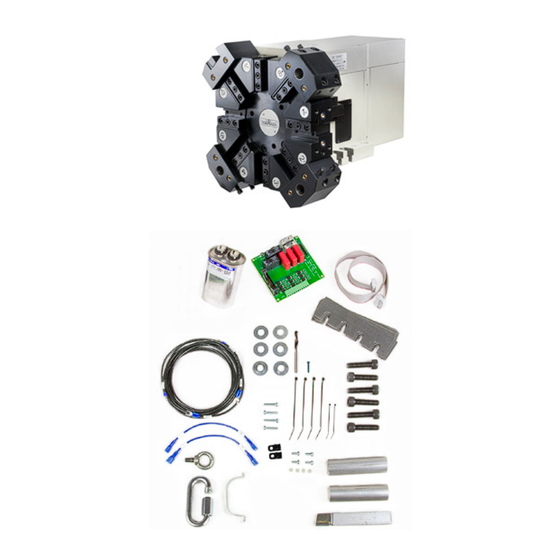
OWNER'S GUIDE: TURRET FOR 15L SLANT-PRO LATHE
Product Identification: Turret Kit for 15L Slant-PRO (PN 37335)
Purpose: This document gives instructions to install the eight-position turret
on a 15L Slant-PRO lathe.
IMPORTANT! You must install the turret before installing the lathe enclosure.
Qty
Turret Installation Kit
1
Eight-Position Turret
1
Turret Control Board
1
Shim Kit
1
Ribbon Cable
1
Capacitor
1
Capacitor Bracket
4
M4 × 10 mm Pan Head Screw
4
M4 × 10 mm Spacer
4
M4 × 20 mm Phillips Screw
1
Turret Installation Wiring Kit
2
Test Piece
1
Cemented Carbide OD Turning Tool
6
M10 × 30 mm Socket Head Cap Screw
6
M10 Flat Washer
1
Eye Bolt and Shackle (C- or U-Shaped)
2
4 in. Cable Tie w/ Mounting Tab
4
11 in. Cable Tie
1
OD Turning/Facing Tool Holder (pre-installed)
3
Boring Bar Holder (pre-installed)
1
Coolant Fitting (may be pre-installed)
1
Spare Motor Belt (under motor cover)
1
1/8 in. Drill
1
#8 × 3/4 in. Pan Head Self-Tapping Screw
NOTE: If any of these items are missing, contact Tormach Customer
Service for a replacement at (608) 849-8381.
©Tormach® 2020. All rights reserved.
Specifications subject to change without notice.
TD10413_Turret_Install_0220A
PN
34947
32785
33324
32878
38460
32871
30537
34626
34627
35141
34718
34824
34621
32473
NOTE: Turret is pre-filled with oil and
—
permanently sealed at factory.
—
—
37137
37136
—
36047
34476
38768
Page 1
TORMACH.COM
Advertisement

Related Manuals for Tormach 37335


Summary of Contents for Tormach 37335
- Page 1 1/8 in. Drill 34476 #8 × 3/4 in. Pan Head Self-Tapping Screw 38768 NOTE: If any of these items are missing, contact Tormach Customer Service for a replacement at (608) 849-8381. ©Tormach® 2020. All rights reserved. Specifications subject to change without notice.
- Page 2 If your machine’s serial number is 10193 or higher: • You don’t need to perform the tasks in the section Relocate the Oil Line. Proceed to the section Mechanical Installation to install your turret. ©Tormach® 2020. All rights reserved. Tormach, Inc. Specifications subject to change without notice.
-
Page 3: Mechanical Installation
7. Add one M10 Flat Washer to each screw. 8. Reinstall the M10 x 30 mm Socket Head Cap Figure 2 Screws and M10 Flat Washers to the slots. ©Tormach® 2020. All rights reserved. Tormach, Inc. Specifications subject to change without notice. P: 608.849.8381 / F: 209.885.4534 TD10413_Turret_Install_0220A tormach.com... -
Page 4: Power Off
2. After software loads, turn red E-stop clockwise to release Power On 3. Press green Start button 4. Click Reset on screen ©Tormach® 2020. All rights reserved. Tormach, Inc. Specifications subject to change without notice. P: 608.849.8381 / F: 209.885.4534 TD10413_Turret_Install_0220A tormach.com... -
Page 5: Electrical Schematic
B3 to J1-8 J1-8 T5 to J1-4 B2 to J1-9 J1- 9 J1-10 B1 to J1-5 B4 to J1-10 ©Tormach® 2020. All rights reserved. Tormach, Inc. Specifications subject to change without notice. P: 608.849.8381 / F: 209.885.4534 TD10413_Turret_Install_0220A tormach.com Page 5... - Page 6 IMPORTANT! Make sure that the Turret Harness is free from entanglement through full motion of lathe. Figure 6 ©Tormach® 2020. All rights reserved. Tormach, Inc. Specifications subject to change without notice. P: 608.849.8381 / F: 209.885.4534 TD10413_Turret_Install_0220A tormach.com Page 6...
- Page 7 7. To begin routing the Power and Encoder ends of the Turret Harness into the electrical cabinet, you must first unscrew the removable cover plate from the cabinet-top box (see Figure 9); set screws aside. NOTE: Contact Tormach Technical Support if your lathe does not have a removable cover plate. Cabinet...
- Page 8 NOTE: Holes for mounting the Turret Control Board are pre- drilled and tapped. Figure 12 Turret Control Board Turret Control Board Spacer Lathe Control Board Figure 13 ©Tormach® 2020. All rights reserved. Tormach, Inc. Specifications subject to change without notice. P: 608.849.8381 / F: 209.885.4534 TD10413_Turret_Install_0220A tormach.com Page 8...
-
Page 9: Make Electrical Connections
Control Encoder Connector Block Board (Colors do not represent wire colors) Wire Trough Terminal Block Ground Figure 14 ©Tormach® 2020. All rights reserved. Tormach, Inc. Specifications subject to change without notice. P: 608.849.8381 / F: 209.885.4534 TD10413_Turret_Install_0220A tormach.com Page 9... - Page 10 Control Board as shown in Figure 16. Board NOTE: The Capacitor is non-polar. There is no wrong way to connect. Capacitor Wires Figure 16 ©Tormach® 2020. All rights reserved. Tormach, Inc. Specifications subject to change without notice. P: 608.849.8381 / F: 209.885.4534 TD10413_Turret_Install_0220A tormach.com Page 10...
- Page 11 13. Remove two Wire Trough covers as shown in Figure 14. Route the power and ground wires through the Wire Troughs. Turret Power Wires Figure 18 ©Tormach® 2020. All rights reserved. Tormach, Inc. Specifications subject to change without notice. P: 608.849.8381 / F: 209.885.4534 TD10413_Turret_Install_0220A tormach.com Page 11...
- Page 12 L24 connection on C1 Contactor (see Figure 20). 19. Re-tighten the terminal lock screw above wire L24, securing both terminal wires. Figure 20 ©Tormach® 2020. All rights reserved. Tormach, Inc. Specifications subject to change without notice. P: 608.849.8381 / F: 209.885.4534 TD10413_Turret_Install_0220A tormach.com...
- Page 13 NOTE: If the Turret Ground wire does not reach the Terminal Block, attach the Turret Ground extension (provided). Figure 22 Figure 23 ©Tormach® 2020. All rights reserved. Tormach, Inc. Specifications subject to change without notice. P: 608.849.8381 / F: 209.885.4534 TD10413_Turret_Install_0220A tormach.com...
- Page 14 Lathe Control Board Connect Ribbon Cable Figure 25 ©Tormach® 2020. All rights reserved. Tormach, Inc. Specifications subject to change without notice. P: 608.849.8381 / F: 209.885.4534 TD10413_Turret_Install_0220A tormach.com Page 14...
- Page 15 X-axis moving dial indicator front to back in Figure 27 the tool pocket (see Figure 27). ©Tormach® 2020. All rights reserved. Tormach, Inc. Specifications subject to change without notice. P: 608.849.8381 / F: 209.885.4534 TD10413_Turret_Install_0220A tormach.com...
- Page 16 For example, .002” + .011” = .013”. This is the shim thickness required to be inserted under the front of turret. The .011” number represents shim thickness required to be placed under the back of turret. ©Tormach® 2020. All rights reserved. Tormach, Inc.
- Page 17 X-axis. 14. Once the adjustment is complete, securely tighten all six Socket Head Cap Screws. Figure 31 ©Tormach® 2020. All rights reserved. Tormach, Inc. Specifications subject to change without notice. P: 608.849.8381 / F: 209.885.4534 TD10413_Turret_Install_0220A tormach.com...
- Page 18 Figure 33. If removal or relocation is necessary, unscrew four bolts on each. Boring Holder Figure 33 ©Tormach® 2020. All rights reserved. Tormach, Inc. Specifications subject to change without notice. P: 608.849.8381 / F: 209.885.4534 TD10413_Turret_Install_0220A tormach.com...
- Page 19 Bolt into the center hole and — while holding the tool with hand — screw in the Extraction Bolt until the tool comes free. Figure 35 ©Tormach® 2020. All rights reserved. Tormach, Inc. Specifications subject to change without notice. P: 608.849.8381 / F: 209.885.4534 TD10413_Turret_Install_0220A tormach.com...
- Page 20 (cutting air) at decreased feed rates. Take every precaution necessary to avoid a tool crash. Choosing which tool is mounted in which turret position is extremely important. Since operator machining setups vary widely, Tormach is unable to instruct where to mount your tools. This following section is intended to give some general pointers on tool mounting.
- Page 21 3/4” Holder Nominal Tooling Size Tormach advises ¾” tooling for the turret, but it is possible to use smaller tool holders (see Figure 37). Keep in mind that these must be shimmed so tool tip is in line with the spindle axis.
- Page 22 Figure 40 ©Tormach® 2020. All rights reserved. Tormach, Inc. Specifications subject to change without notice. P: 608.849.8381 / F: 209.885.4534 TD10413_Turret_Install_0220A tormach.com...
-
Page 23: Troubleshooting
NOTE: Spare Motor Belt located under Figure 41 Motor Cover (see Figure 42). Motor Belt Spare Motor Belt Figure 42 ©Tormach® 2020. All rights reserved. Tormach, Inc. Specifications subject to change without notice. P: 608.849.8381 / F: 209.885.4534 TD10413_Turret_Install_0220A tormach.com Page 23... - Page 24 Lock loosen two screws on the lock Switch switch bracket (see Figure 44). Lock Switch Bracket Figure 44 ©Tormach® 2020. All rights reserved. Tormach, Inc. Specifications subject to change without notice. P: 608.849.8381 / F: 209.885.4534 TD10413_Turret_Install_0220A tormach.com Page 24...
- Page 25 8. Move the bracket right until multimeter reads 24 volts (see Figure 46). 9. Re-tighten the bracket and re-install the motor cover. Figure 46 ©Tormach® 2020. All rights reserved. Tormach, Inc. Specifications subject to change without notice. P: 608.849.8381 / F: 209.885.4534 TD10413_Turret_Install_0220A tormach.com...
- Page 26 Figure 48 3. Put the disconnected oil line back through the carriage (see Figure 49). 4. Reconnect the oil line to the manifold (see Figure 47 and inset). ©Tormach® 2020. All rights reserved. Tormach, Inc. Specifications subject to change without notice.
- Page 27 12. Use a #19 drill, M5 × 0.8 tap, and a Bracket tapping handle to drill and tap the Drill Hole marked location. Figure 51 ©Tormach® 2020. All rights reserved. Tormach, Inc. Specifications subject to change without notice. P: 608.849.8381 / F: 209.885.4534 TD10413_Turret_Install_0220A tormach.com Page 27...
- Page 28 Hole 5/8” (see Figure 53 and Figure 54). Figure 52 Figure 54 Figure 53 ©Tormach® 2020. All rights reserved. Tormach, Inc. Specifications subject to change without notice. P: 608.849.8381 / F: 209.885.4534 TD10413_Turret_Install_0220A tormach.com Page 28...
Need help?
Do you have a question about the 37335 and is the answer not in the manual?
Questions and answers