Tormach PCNC 770 Operator's Manual
Benchtop cnc milling machine
Hide thumbs
Also See for PCNC 770:
- Quick start manual (4 pages) ,
- Technical document (5 pages) ,
- Assembly manual (13 pages)
Table of Contents
Advertisement
Quick Links
Tormach
PCNC 770
®
™
Operator Manual
IMPORTANT: Read and understand all operator manual safety precautions and instructions
before attempting PCNC 770 installation, operation, or maintenance.
Questions or comments?
UM10350_PCNC770_Manual_0916A
Please email us: info@tormach.com
Document Part Number: 35427
All rights reserved.
©2015 Tormach Inc.
Advertisement
Table of Contents
Troubleshooting

Subscribe to Our Youtube Channel
Related Manuals for Tormach PCNC 770


Summary of Contents for Tormach PCNC 770
- Page 1 PCNC 770 ® ™ Operator Manual IMPORTANT: Read and understand all operator manual safety precautions and instructions before attempting PCNC 770 installation, operation, or maintenance. Questions or comments? UM10350_PCNC770_Manual_0916A Please email us: info@tormach.com Document Part Number: 35427 All rights reserved.
-
Page 2: Operation
Safety Overview Any machine tool is potentially dangerous. The automation inherent in a CNC mill presents added risk not present in a manual mill. Tormach CNC mills can deliver sufficient force to break brittle tools, crush bones, and tear flesh. - Page 3 Preface Machine Safety Safe operation of the machine depends on its proper use and the precautions taken by the operator. Read and understand this manual prior to mill use. Only trained personnel — with a clear and thorough understanding of its operation and safety requirements — should operate this mill. General Safety: •...
-
Page 4: Electrical Safety
Failure to do so may result in serious injury or death. Input Power: The PCNC 770 has one 115 V power input which is capable of delivering lethal electrical shocks. Care should be exercised when working inside the electrical cabinet. - Page 5 All information provided is on an as is basis. The authors, publisher, and Tormach Inc. shall not have any liability for, or responsibility to, any person or entity for any reason for any loss or damage arising from the information contained in this manual.
- Page 6 Preface Intended Use Statement The PCNC 770 is intended for use as a general purpose CNC milling machine. The intended use includes cutting conventional (non-abrasive) materials such as unhardened mild or alloy steels, aluminum, plastics, wood, and similar materials (or any other material that can be cut with a rotating cutter).
- Page 7 Includes additional contributing factors such as compressibility of bearings, ball screw windup, friction, etc. Each PCNC mill ships with a Certificate of Inspection. This report details quality assurance measurements performed at the factory by a Tormach quality assurance team member on each mill prior to shipping.
- Page 8 Preface Table of Contents 1. Overview 1.1 Specifications (PCNC 770) 2. Site Planning and Prep 2.1 General Site Requirements 2.1.1 Space Requirements 2.2 Electrical Requirements 2.2.1 Grounding 2.2.2 Plug Pattern 2.2.3 Ground Fault Interrupter (GFI) Use 2.2.4 Electrical Noise 2.2.5 Options for Electrically Non-conforming Sites 2.2.5.1 Buck-Boost Transformer 2.2.5.2 Step-up/Step-down Transformer 2.2.5.3 Quick 220 Voltage Converter Power Supply ™...
-
Page 9: Table Of Contents
Preface 3.3.5 Lift and Move Mill 3.3.5.1 Remove Mill from Pallet 3.3.5.2 Lifting Bar Kit 3.3.5.3 Lifting from Below 3.3.5.4 Moving Kit (PCNC 770 Only) 3.3.5.5 Lowering Mill onto Stand 3.3.6 Install Tool Tray (PCNC 1100 only) 3.3.7 Install Drip Tray 3.3.8 Install PathPilot Controller 3.4 Installation of Add-ons 3.4.1 Stand 3.4.2 Machine Arm... - Page 10 Preface 4. Operation 4.1 Control Locations 4.1.1 Operator Panel 4.1.2 PathPilot Interface 4.2 Initializing the Mill 4.2.1 Vital Reference 4.3 Jogging 4.3.1 Manual Control Group 4.4 Spindle Controls 4.4.1 Manual Spindle Control Via Operator Panel 4.4.2 Automated Spindle Control Via PathPilot Interface 4.4.3 Changing Spindle Speed Range 4.5 Tool Holders 4.6 Part Setup/Workholding 5. Intro to PathPilot 5.1 Making Your First Part 5.1.1 Referencing the Mill...
- Page 11 Preface 6.2.1 Program Control Group 6.2.2 Position Status Group 6.2.3 Manual Control Group 6.2.4 Keyboard Shortcuts 6.3 Main Tab 6.4 File Tab 6.5 Settings Tab 6.6 Offsets Tab 6.6.1 Tool Tab 6.6.1.1 Offline Measurement with Height Gauge 6.6.1.2 Automated Measurement with an Electronic Tool Setter 6.6.1.3 Measurement by Touching Off Tool 6.6.2 Offsets Table 6.6.3 Tool Offset and Fixture Information Backup 6.6.4 Work Tab 6.7 Conversational Tab...
- Page 12 Preface 6.8.1 XYZ Probe Tab 6.8.2 Rect/Circ Tab 6.8.3 Probe/ETS Setup Tab 6.9 ADMIN Commands 7. Programming 7.1 Definitions 7.2 G-code Programming Language 7.2.1 Overview 7.2.2 Block 7.2.3 Real Value 7.2.4 Number 7.3 Formatting G-code Blocks 7.3.1 Optional Program Stop Control – (M01 BREAK) 7.4 Additional G-code Formatting Notes 7.4.1 Repeated Items 7.4.2 Order of Execution 7.4.3 Error Handling 7.4.4 Modality and Modal Commands 7.4.5 Modal Groups...
- Page 13 Preface 7.5.5 Set Offsets – G10 7.5.5.1 Set Tool Table – G10 L1 7.5.5.2 Set Coordinate System – G10 L2 7.5.5.3 Set Tool Table – G10 L10 7.5.5.4 Set Tool Table – G10 L11 7.5.5.5 Set Coordinate System – G10 L20 7.5.6 Plane Selection – G17, G18 and G19 7.5.7 Length Units –...
- Page 14 Preface 7.6.2.4 G83 Cycle 7.6.2.5 G85 Cycle – Boring Cycle (Feed rate out) 7.6.2.6 G88 Cycle – Boring Cycle (Dwell, Manual Out) 7.6.2.7 G89 Cycle – Boring Cycle (Dwell, Feed rate out) 7.6.2.8 Distance Mode – G90 and G91 7.6.2.9 Arc Distance Mode – G90.1, G91.1 7.6.2.10 Temporary Work Offsets –...
- Page 15 Preface 7.9.2 Parameter Types 7.9.2.1 Numbered Parameters 7.9.2.2 Subroutine Parameters 7.9.2.3 Named Parameters 7.9.3 Expressions 7.9.3.1 Binary Operators 7.9.3.2 Functions 7.10 Programming with Subroutines 7.10.1 Subroutine Labels and Subroutine Keywords 7.10.1.1 Defining a Subroutine 7.10.1.2 Calling a Subroutine 7.10.1.3 Conditional Subroutines 7.10.1.4 Repeating Subroutines 7.10.1.5 Looping Subroutines 8. Accessories 8.1 4th Axis Kits 8.2 Enclosures, Stands, and Machine Arms 8.3 Tapping Options 8.4 Oil And Coolant System Options 8.4.1 Automatic Oiler...
- Page 16 Preface 8.5.1.2 Tormach Speeder 8.5.1.3 High-speed Spindle 8.5.2 Other Spindle Options 8.5.2.1 BT30 Spindle Cartridge 8.5.2.2 Spindle Load Meter 8.5.2.3 LED Spindle Light 8.6 Power Drawbar and ATC 8.6.1 Power Drawbar 8.6.2 Automatic Tool Changer (ATC) 8.7 Auxiliary Electronic Options 8.7.1 External Contactor Kit 8.7.2 Switchable Convenience Outlet Kit 8.7.3 USB M-code I/O Interface Kit 8.7.4 Integrated Remote E-stop Kit...
- Page 17 Preface 9.1.3 Flood Coolant System 9.1.4 Lubrication System 9.1.4.1 Manual Pump Specifics 9.1.5 Drawbar and TTS Collet 9.2 Spindle Belt 9.3 Advanced Maintenance 9.3.1 Overview 9.3.2 Definitions 9.3.2.1 How to Measure Lost Motion 9.3.3 Gib Adjustment 9.3.3.1 Overview 9.3.3.2 Adjustment Procedure 9.3.4 Angular Contact Bearing Preload Adjustment 9.3.4.1 Overview 9.3.4.2 Adjustment Procedure 9.3.4.3 Determining Proper Angular Contact Bearing Preload 9.3.5 Geometry Adjustment of Precision Mating Surfaces 9.4 Spindle Bearing Adjustment 9.5 Spindle Calibration...
- Page 18 Preface 10.2.4.1 Measuring DC Voltage 10.2.4.2 Measuring AC Voltage 10.2.4.3 Measuring Resistance 10.2.5 Contacting Technical Support 10.3 Frequently Found Problems 10.3.1 Loose Wires 10.3.2 Wire Hairs 10.3.3 Poor Cable Connections 10.3.4 Sensors (Limit Switches) 10.3.5 Unexplained Stop or Limit Switch Error While Running 10.4 Electrical Maintenance 10.4.1 Electrical Service 10.5 System Troubleshooting 10.5.1 Power Distribution Subsystem 10.5.1.1 Overview 10.5.1.2 Details of Power Distribution Subsystem 10.5.2 Control Power Subsystem...
- Page 19 Preface 11. Diagrams and Parts List 11.1 Upper Mill Assembly (exploded view) 11.2 Lower Mill Assembly (exploded view) 11.3 Electrical Cabinet 11.4 Connections 11.5 Stepper Connection 11.6 Operator Panel 11.7 Ribbon Cable and Miscellaneous 11.8 Lubrication System Chapter 1 UM10350_PCNC770_Manual_0916A...
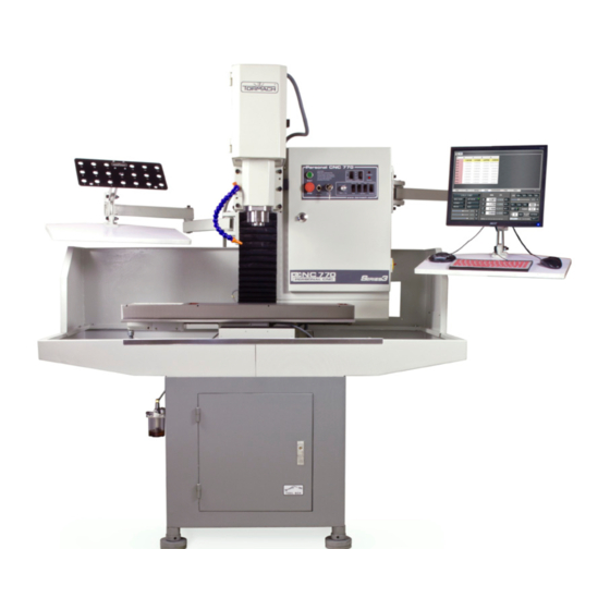
- Page 20 Overview 1. Overview Tormach PCNC mills are intended for use as general purpose CNC mills. Pictured below is a typical PCNC 770 mill set up, including several options. Figure 1.1 Item # Component Item # Component Electrical Cabinet PathPilot Interface ®...
-
Page 21: Specifications (Pcnc 770)
Overview 1.1 Specifications (PCNC 770) Mechanical Length 28” Width 8” T-Slot Width 5/8” T-Slot Center-to-Center Distance 2” Dimensions Three along X Axis Number of Standard T-Slots (machine (Center slot precision ground to 0.625”) table) Maximum Weight on Table 400 lbs. -
Page 22: Site Planning And Prep
The PCNC 1100 is shipped with a 3-wire conductor; no electrical plug is included. There are several different NEMA (National Electric Manufacturers Association) and non-NEMA plug patterns that can be used. The PCNC 770 is shipped with a 5-20P plug. This plug is designed to be used with a 5-20R receptacle. -
Page 23: Ground Fault Interrupter (Gfi) Use
If needed, a Step-Up/Step-Down Transformer (PN 32009) can be used to reduce 230 VAC line voltage to 115 VAC, as required by the PCNC 770. This device is commonly used for PCNC 770 mills located outside of the USA and Canada. -
Page 24: Installation
Installation 3. Installation This chapter covers basic installation of a PCNC mill, which takes approximately half a day. This estimate does not include optional accessories like enclosures, power drawbars, or automatic tool changers (ATC). Scan the QR code (at right) to view a list of related technical documentation, operator manuals, and support videos: http://www.torma.ch/install Recommended for Installation •... -
Page 25: Initial Uncrating
Installation 3.1.3 Initial Uncrating CAUTION! Sharp Objects: Be sure to wear gloves when uncrating mill. Failure to do so may result in serious injury. Use strap snips and a small pry bar to open and disassemble shipping crate. Remove top of crate first, followed by four sides. -
Page 26: Remove Tool Tray (Pcnc 1100 Only)
Installation 3.3.2 Remove Tool Tray (PCNC 1100 only) Carefully remove the Tool Tray from the pallet and set aside for installation later (see Figure 3.7). 3.3.3 Remove Accessory Tool Box A wooden Tool Box is nailed to the pallet (see Figure 3.2). This box contains tools that are required for installation. -
Page 27: Lift And Move Mill
Machine Measurement PCNC 1100 37” PCNC 770 29” 3.3.5.3 Lifting from Below It is also possible to lift the mill from below by inserting steel bars into two sets of opposing 7/8” diameter holes located in the machine base. The bars must be a minimum of 32” in length and should be made of solid steel. -
Page 28: Moving Kit (Pcnc 770 Only)
Installation 3.3.5.4 Moving Kit (PCNC 770 Only) The PCNC 770 can be temporarily disassembled using the Moving Kit (PN 31333). This allows the machine to be broken down into several smaller subcomponents. Refer to documentation that ships with Moving Kit for more information on use. -
Page 29: Install Pathpilot Controller
Ethernet Connector Audio Connections* Mill Interface Port Voltage Setting Switch Figure 3.9 PCI Expansion Slot AC Power Connector *NOTE: Do not use these controller features. PCNC 770 Power Connection Panel PCNC 1100 Power Connection Panel DB-25 Controller DB-25 Controller Coolant Monitor... - Page 30 Installation Set up and connect the PathPilot controller as follows: 1. Confirm Voltage Setting Switch (#15) is set to proper voltage for the geographic location before connecting power. Plug the power cord into the AC Power Connector (#17) on the PathPilot controller. 2.
-
Page 31: Installation Of Add-Ons
Machine Arm for PCNC 1100 or PCNC 770 (PN 30286) • Machine Arm for PCNC 1100 or PCNC 770 with Full Enclosure (PN 34668) 3.4.2.1 Mouse, Keyboard, and Jog Shuttle Carefully route the USB device cables inside the machine arm and into the controller compartment. -
Page 32: Essential Controls Overview
Installation 3.5 Essential Controls Overview Check to ensure your local power supply meets the requirements detailed in chapter 2, Site Planning and Prep. 3.5.1 E-stop, Start, Reset, and Power Start NOTE: Before continuing, review Power Off/On E-stop Procedure later in this section. E-stop (emergency stop) Each mill has one emergency Stop button or E-stop pre-installed on the Operator Panel (see... -
Page 33: Power Off/Power On Procedure
Installation PathPilot Interface Figure 3.17 Reset Click the PathPilot interface’s Reset button to establish communications between controller and mill (see Figure 3.17). The Controller LED on the operator panel indicates when communication has been established. Main Disconnect The Main Disconnect switch, located on the right side of the electrical cabinet, is used to power the mill off and on (see Figure 3.13). -
Page 34: Initial Pathpilot Controller Configuration
The first time the PathPilot controller is powered on it starts a configuration process that allows the operator to configure the PathPilot operating system to the particular machine (PCNC 1100 mill, PCNC 770 mill, PCNC 440 mill, or 15L Slant-PRO lathe). Follow the on-screen instructions to complete controller configuration. After configuration, PathPilot automatically launches; the controller automatically loads PathPilot for the selected machine when the controller is powered on in the future. -
Page 35: Verify Limit Switch Function
Installation 3.7.2 Verify Limit Switch Function Limit switches prevent the mill from exceeding its travel limits and provide a reference location during the mill homing procedure. There are three limit switches, one for each axis of motion (X, Y, and Z). Refer to Figure 3.18 for the location of each limit switch. -
Page 36: Verify Axis Function
Installation 3.7.3 Verify Axis Function 1. Reference the mill by clicking the Ref Z, Ref X, and Ref Y buttons (see Figure 3.19); the mill moves. 2. Next, switch to the Main screen. 3. Use keyboard to verify axis motion: a. -
Page 37: Controller Customization
Installation 3.8 Controller Customization Date and Time To set or edit controller’s date and time, type ADMIN DATE in the MDI field and click Enter on keyboard (see Figure 3.20). This opens a dialog box to enter or edit date, time, and time zone. Click Close when finished. -
Page 38: Operation
It also contains the Accessory inlet, the Spindle Speed Dial (RPM x 100), and Spindle Lockout. NOTE: The Operator Panel is not compatible with the PCNC 1100 or PCNC 770 full enclosure kit and is therefore removed and discarded during installation of either. In this scenario, these controls are accessed (on mills without an operator panel) via the PathPilot interface. -
Page 39: Initializing The Mill
(see Figure 4.2). Jogging Controls Tormach mills can be jogged with either the Jog Shuttle (PN 30616) shown in Figure 4.4 or by using the keyboard’s arrow keys (see Figure 4.3): •... -
Page 40: Spindle Controls
Operation Jogging with Keyboard Keys Jog Shuttle Wheel A-Axis Motion Shuttle X-Axis Motion Ring Figure 4.3 Figure 4.4 Jog Shuttle The Jog Shuttle (PN 30616), shown in Figure 4.4, is an optional accessory that many operators find increases productivity, especially on short-run jobs requiring extensive setting up of the workpiece and tooling. -
Page 41: Automated Spindle Control Via Pathpilot Interface
Each PCNC mill has two speed ranges as outlined in the table below. High PCNC 1100 100-2000 250-5140 PCNC 770 175-3250 525-10,020 The range change is performed by moving the spindle belt from the top pair of pulleys (high speed range) to the lower pair of pulleys (low speed range). -
Page 42: Tool Holders
• Quickest manual tool change time • Shortest tool change clearance distance • Compatibility with Tormach power drawbar and Tormach automatic tool changer (ATC) TTS uses a precision 3/4” collet in combination with a drawbar and interchangeable TTS tool holders. -
Page 43: Part Setup/Workholding
X-axis. The slots are precision ground to: Center Slot Outer Slots -0.00 + 0.004” 0.000 + 0.008” A 5” vise is recommended. Tormach offers the following vises: PCNC 1100 PCNC 770 PN 31759 or PN 30553 PN 31759 For more information on proper setup and use of the 5”... -
Page 44: Intro To Pathpilot
5. Intro to PathPilot 5.1 Making Your First Part This chapter outlines how to make your first part with a Tormach mill. It assumes that you have no prior experience running a part program on a CNC (computer numerically controlled) mill. Even if you have previous... -
Page 45: Workpiece Preparation
1/8” or smaller diameter end mill to engrave the text (see Figure 5.3). You will also need a way to hold these tools. Tormach’s High Tool 2 Speed Steel End Mill Kit (PN 33465) includes both end mills. -
Page 46: Setting Work Offset By Touching Off Workpiece
Intro to PathPilot Tool Offsets Tool offsets allow the operator to use tools of different length and (in the case of cutter radius compensation) different diameters. In the program you will create during this tutorial, you will use two different tools. Because it is extremely unlikely that these tools will be exactly the same length, the control needs to account for the difference in tool length when switching tools. - Page 47 Intro to PathPilot 2. Type 0 in the tool DRO and press the M6 G43 button to tell the PathPilot operating system that we are changing tools and applying a tool length offset. Tool zero represents an empty spindle, and there is no offset to apply.
-
Page 48: Setting Tool Length Offset By Touching Off Workpiece
Intro to PathPilot 5.1.4.2 Setting Tool Length Offset by Touching Off Workpiece This section assumes that you have already set the work offset Z zero to the top surface of the part using the steps in Setting Work Offset by Touching off Workpiece. The steps below describe an alternative to using the TTS height gauge. -
Page 49: Writing The G-Code
Intro to PathPilot 7. Type 2 in the tool DRO and click the M6 G43 button (see Figure 5.5). 8. Repeat steps 3-6 to measure the tool length for Tool 2. 5.1.5 Writing the G-code Now use Conversational programming capabilities of the PathPilot interface to generate G-code to produce our part (see Figure 5.1). - Page 50 Intro to PathPilot Make note of a few things: • Units are expressed according to the current G20/21 setting. If you are in G21 (metric), the feed rates will be in mm/min and the coordinates in mm. For the purposes of this tutorial, use imperial units (G20).
-
Page 51: Operation 2
Intro to PathPilot Figure 5.12 3. Grab Maxvel slider again and slowly increase allowed velocity (see Figure 5.12). Bring velocity back down to zero when you get close to the part and double check values in the DROs to make sure that tool position looks correct. For example, if tool is 1/4” above the workpiece, Z DRO should read 0.2500. - Page 52 Intro to PathPilot Conversational DROs Figure 5.13 3. Click on the name of the file you created when you made the facing G-code, then click Append to File (see Figure 5.14). The changes to your file are loaded into the control, and you should see a tool path that looks something like Figure 5.15.
-
Page 53: Pathpilot Interface
PathPilot Interface 6. PathPilot Interface 6.1 Overall Layout interface is divided into two sections, the Notebook and the Persistent Controls The PathPilot ® (see Figure 6.1). The Persistent Controls make up the bottom half of the screen and include three control groups: the Program Control Group, the Position Status Group, and the Manual Control Group. -
Page 54: Persistent Controls
Persistent Controls half of the PathPilot interface contains the controls used to set up a job and execute G-code. Operators already familiar with Tormach milling machines (or most other CNC machines) will be familiar with many of the Persistent Controls buttons. - Page 55 PathPilot Interface • Cycle Start is pressed when no G-code program is loaded • Cycle Start is pressed before the mill has been referenced Single Block – Turns Single Block on (LED illuminated) or off. When Single Block mode is active, the mill executes one block of G-code, then pauses and flashes the Cycle Start button LED on and off, inviting the operator to press the Cycle Start button to execute the next line of G-code.
-
Page 56: Position Status Group
PathPilot Interface • Clears alarms (for more information on alarms, see the Status tab section) • Clears the tool path backplot Spindle Override – The Spindle Override Slider and RPM 100% button (see Figure 6.2) allow you to override the commanded spindle speed by percentages ranging from 1 percent to 150 percent. The RPM 100% button returns the override to 100 percent of the commanded value or no override. -
Page 57: Manual Control Group
PathPilot Interface When the mill is at rest, these readouts are also operator entry fields. Change the current work offset position by clicking in the DRO field, which illuminates. Type a number, for example 4.0, and click Enter on keyboard. Press the Esc key to return to the original value. This technique is used for setting any DRO. - Page 58 Figure 6.5 Figure 6.6 Tormach mills can be jogged with either the Jog Shuttle shown in Figure 6.5 or with the keyboard’s arrow keys (see Figure 6.6): • The right arrow jogs X-axis in the positive X direction (moves table left of operator) •...
- Page 59 PathPilot Interface Step Size Buttons Spindle Jog Speed Jog Cont/ Slider Step Figure 6.8 Figure 6.7 Whether using the jog shuttle or the keyboard arrow keys, there are two modes of jogging, continuous and step. When using the keyboard to jog, switch between modes using the Jog Cont/ Step button (see Figure 6.7).
-
Page 60: Keyboard Shortcuts
PathPilot Interface The Spindle RPM DRO is used to display the current spindle speed command (see Figure 6.8). You may change the current spindle speed command by typing a value into this DRO and pressing Enter. Values above the maximum RPM or below the minimum RPM for the current belt position triggers an alarm. The Spindle Range button toggles between the two belt/pulley settings with an LED indicating which position is active (see Figure 6.8). - Page 61 PathPilot Interface Recent Files Drop-down Menu Figure 6.9 Recent Files Drop-down Menu – The top left portion of the Main screen has a Recent Files Drop-down Menu that displays the currently loaded G-code file (see Figure 6.9). Clicking on it displays the names of the last five files that have been loaded into the control.
- Page 62 PathPilot Interface MDI Line – When running a G-code part program, commands to the mill are read from a file. It is MDI Line often convenient to send G-code commands to the mill directly. This can be done by typing a command into the Manual Data Input line (MDI Line), as shown in Figure 6.10.
- Page 63 PathPilot Interface When used in conjunction with the FIND command, certain search terms (listed below) initiate a search through the G-code file to find more than just the actual search term: • FIND TOOL: Searches for instances of the actual word Tool in the G-code and any T G-code command, which calls up a tool (e.g., T12) •...
-
Page 64: File Tab
PathPilot Interface 6.4 File Tab The File tab screen is used to transfer files to and from a USB drive, copy, delete, and rename files and folders (see Figure 6.14). The left window shows files and folders on the controller hard drive; the middle window shows files and folders on a removable USB drive. -
Page 65: Settings Tab
PathPilot Interface 6. When copied to the new location, the file displays in the USB Drive Window. 7. Click the Eject button to disconnect the USB drive from the controller (see Figure 6.14). NOTE: Ejecting the USB drive this way helps to avoid corrupting data on the USB drive. File Management Use the New Folder, Rename, and Delete buttons below the respective USB Drive and Hard Drive Windows for file management (see Figure 6.14). - Page 66 PathPilot Interface Figure 6.15 Automatic Tool Changer (ATC) – If the ATC option is selected, the PathPilot operating system searches for an ATC attached to the mill. If the mill is equipped with an ATC, tools that have been assigned to the tray are changed automatically when a Tx M6 command is issued via MDI or G-code program.
- Page 67 Press Enter to accept the value that has been typed. Press ESC to exit the on-screen keypad and restore the previous value. Probe Options – Tormach has two probes available: a Passive Probe (PN 32310) and an industrial grade Digitizing Probe (PN 31858). Instruct PathPilot which type of probe is attached to the mill before using the probing buttons.
-
Page 68: Offsets Tab
PathPilot Interface Switch to RapidTurn – Closes the PathPilot interface and opens PathPilot interface for the RapidTurn ™ (PN 32901). For information on operating the RapidTurn and related interface, refer to the RapidTurn operator manual. 6.6 Offsets Tab The Offsets tab reveals two sub tabs, Tool and Work (see Figure 6.18). Work offsets are a concept that allow the operator to think in terms of X/Y/Z coordinates with respect to the part instead of thinking of them with respect to the mill position. -
Page 69: Offline Measurement With Height Gauge
• Measurement by touching off tool to a reference surface 6.6.1.1 Offline Measurement with Height Gauge Setup: The Tormach Tool Assistant Set (PN 31988) includes an 8” digital height gauge and a USB interface cable with touch trigger (see Figure 6.19). When this device is plugged into one of the controller’s USB ports, the Zero Height Gauge button... -
Page 70: Measurement By Touching Off Tool
PathPilot Interface 6.6.1.3 Measurement by Touching Off Tool This method was covered in chapter 5, Intro to PathPilot. It is not as accurate as the two methods described above, but works in many situations. 6.6.2 Offsets Table The Offsets Table on the Offsets screen (see Figure 6.18) displays an editable table of tool offsets (both geometry offsets and wear offsets) as well as a read-only table of work offsets. -
Page 71: Conversational Tab
PathPilot Interface 6.7 Conversational Tab 6.7.1 Face Tab Face is generally used for cutting an accurate top surface from rough stock, cutting successive XY-planes over a Z range (see Figure 6.20). Figure 6.20 It is assumed that the top of the stock is free of any clamps or other work holding devices, such as when the stock is held in a vise. -
Page 72: Profile Tab
PathPilot Interface Stepover – This is the space between spiral tool paths. To prevent uncut areas in the spiral corners, the stepover value should be limited to 80 percent of the tool diameter (see Figure 6.21). A stepover of 0 may be entered which invokes a center only cut. -
Page 73: Pocket Tab
PathPilot Interface The outer bound of the area is the stock material's outer edges. The inner bound is the island perimeter. For the cutting routine, the area is divided into four sections (north, east, south, and west). As with Face, the starting position for cutting each section is off the workpiece with an X or Y feed into the workpiece, thus avoiding a Z plunge cut. - Page 74 PathPilot Interface Figure 6.23 If tool diameter is bigger than pocket width no G-code being produced, an error appears on the Status tab. If the tool just fits within the pocket width and length, a straight Z plunge in the pocket center is used, therefore a center cutting end mill is needed.
-
Page 75: Circular
PathPilot Interface Z DROs Z Start and End – The first Z pass will cut at Z Start – Depth of Cut adjusted. The last Z pass cuts at the Z End location. For a single Z pass at Z End, enter 0 or a full Z range value into the Depth of Cut DRO. Depth of Cut –... -
Page 76: Drill/Tap Tab
PathPilot Interface XY DROs X and Y Center – These DROs should be set to the location of the pocket center. Pocket Dia. – Enter the value of the pocket diameter. The tool radius is used to set the tool path diameter. - Page 77 PathPilot Interface Pattern DROs Hole Location Table – This table should be used for making a list of X and Y locations for each hole using the same tool, Z, and common DRO entries (see Figure 6.25). To create holes using different tools or other parameters, post the first group, clear the table, enter the next group of locations and other parameters, then append the new list to the existing posted file.
-
Page 78: Drill
PathPilot Interface Circular DROs Number of Holes – Specifies the number of holes in the pattern. This must be greater than zero. Start Angle – Specifies the angle from angle 0. Angle 0 is a base (horizontal) line from the center point going right (east) to the circumference. -
Page 79: Tap
PathPilot Interface Z DROs Z Start and End – G8x starts at the Z Clear location and ends at Z End location. Z Clear – This is the Z location the tool moves or retracts to at the start, end, and while pecking, as well as moving between holes, so it must clear any obstructions along the path between holes. -
Page 80: Thread Mill Tab
PathPilot Interface Z Clear – This is the Z location the tool moves or retracts to at the start and end of a hole, as well as moving between holes, so it must clear any obstructions along the path between holes. 6.7.5 Thread Mill Tab The thread milling routine produces helical tool paths needed for milling straight external or internal right-handed threads based on pitch, diameter, and length (see Figures 6.28 and 6.29). - Page 81 PathPilot Interface Thread Table – Contains values for some common threads. The threads listed follow the current unit setting (inch or millimeter). Once a selection is made, the data from the selected thread is copied to the appropriate DROs. This table is stored in user-editable text files found in the thread_data subdirectory of the G-code folder on the controller's hard drive;...
-
Page 82: Engrave Tab
PathPilot Interface Figure 6.30 6.7.6 Engrave Tab The Engrave tab (see Figure 6.30) contains functions to engrave a single line of text cut in a single horizontal pass (along the X-axis). This is a basic text engraving routine best suited for engraving True Type stick or outline fonts into things like simple plaques, control panels, or data plates. - Page 83 PathPilot Interface Figure 6.31 SN Start – Sets a starting serial number. Add zeros in front of the first digit as a hint to the number of decimals to be engraved in the series (including leading zeros). For example, if '0012' is entered, '0012,' '0013,' '0014,' '…' will be engraved.
-
Page 84: Probe Tab
PathPilot Interface Figure 6.32 6.8 Probe Tab The Probe tab of the notebook contains automated functions to find X/Y/Z locations, set work offsets, probe pockets, slots or bosses, as well as instructions on probe and toolsetter setup and calibration. The Probe tab contains a separate, smaller notebook that consists of three tabs: •... -
Page 85: Rect/Circ Tab
PathPilot Interface Figure 6.33 The Probe (Axis), Set Work Offset buttons will probe in one axis only and set the current work offset origin to the probed surface for that axis. The direction of probing is specified by the + or – sign on the button and is described by the accompanying graphic. -
Page 86: Probe/Ets Setup Tab
PathPilot Interface Figure 6.34 6.8.3 Probe/ETS Setup Tab The Probe/ETS Setup tab is used to align and set the probe and ETS heights (see Figure 6.34). For information on probe and ETS setup, refer to chapter 8, Accessories. 6.9 ADMIN Commands Several ADMIN commands are provided for operator use. -
Page 87: Programming
G-code programming. 7.1 Definitions The following terms are defined as follows: PathPilot This is the Tormach motion controller. PathPilot Operating System (OS) This is the PathPilot controller operating system. Coordinate System A coordinate system identifies the position of geometric features like points, lines, etc., in space. The default coordinate system in PathPilot is a standard right-hand coordinate system. - Page 88 Programming Rotational Axis The A-axis is a rotational axis. In general, the axis of rotation can be collinear to a primary linear axis, or arbitrary. In usual practice, the axis of rotation of the A-axis is typically collinear to the X-axis. Position is measured in degrees.
- Page 89 Programming It is possible, however, to control the axes so that, at all times, each axis has completed the same fraction of its required motion (as the other axes) and the tool maintains a straight line motion. Arc and Helical Motion Any pair of the linear axes (XY, YZ, and XZ) can be controlled to move in a circular arc in the plane of that pair of axes.
-
Page 90: G-Code Programming Language
Programming Feed and Speed Override Controls The operating system has commands which enable (M48) or disable (M49) the feed and speed override slider controls. It is useful to be able to override these for some machining operations. Default settings in the program are set and the operator should not change them. 7.2 G-code Programming Language IMPORTANT! Do not use a word processor to create or edit G-code files. -
Page 91: Formatting G-Code Blocks
Programming The following rules are used for explicit numbers. In these rules a digit is a single character between 0 and 9. • A number consists of the following, in order: (1) an optional plus or minus sign, followed by (2) zero to many digits, followed, possibly, by (3) one decimal point, followed by (4) zero to many digits. - Page 92 Programming Spaces and tabs are allowed anywhere on a line of code and do not change the meaning of the line, except inside comments. For example, the line: G00 x +0. 12 34y 7 is equivalent to: G00 x+0.1234 y7 Blank lines are allowed in the input, but are ignored.
- Page 93 Programming (...continued) Word Initial Leters Letter Meaning Z-axis offset for arcs Z offset in G87 canned cycle Number of repetitions in canned cycles/subroutines Key used with G10 Miscellaneous function Line number Subroutine label number Dwell time in canned cycles Dwell time with G04 Key used with G10 Tapping depth in M871 –...
-
Page 94: Optional Program Stop Control - (M01 Break)
Programming Display a Message - (MSG) (MSG, …) - displays a message if MSG appears after the left parenthesis and before any other printing characters. Variants of MSG which include white space and lowercase characters are allowed. The rest of the characters before the right parenthesis are considered to be a message. Messages are displayed on the Status screen. - Page 95 Programming If the second group (the parameter settings) is reordered, there is no change in the meaning of the line unless the same parameter is set more than once. In this case, only the last setting of the parameter takes effect. For example, after the line: #3=15 #3=6 has been interpreted, the value of parameter 3 is 6.
-
Page 96: Error Handling
Programming (...continued) Order of Execution Order Item Cutter radius compensation on/off (G40, G41, G42) Tool table offset on/off (G43, G49) Fixture table select (G54 – G58 and G59 P~) Set path control mode (G61, G61.1, G64) Set distance mode (G90, G91) Set canned cycle return level mode (G98, G99) Home, change coordinate system data (G10) or set offsets (G92, G94) Perform motion (G00 to G03, G12, G13, G80 to G89 as modified by G53) -
Page 97: Default Modes
Programming (...continued) Modal Groups for G-codes Group 5 = {G93, G94} feed rate mode Group 6 = {G20, G21} units Group 7 = {G40, G41, G42, G41.1, G42.1} cutter radius compensation Group 8 = {G43, G43.1, G49} tool length offset Group 10 = {G98, G99} return mode in canned cycles Group 12 = {G54, G55, G56, G57, G58, G59, G59.1, G59.2, G59.3} coordinate system selection Group 13 = {G61, G61.1, G64} path control mode... - Page 98 Programming (...continued) Summary of G-codes Dwell G07, G08 Diameter/radius mode – Do not use G08 G10 L1 Set tool table entry G10 L10 Set tool table – calculated – workpiece G10L11 Set tool table – calculated – fixture G10 L2 Set work offset origin G10 L20 Set work offset origin –...
-
Page 99: Rapid Linear Motion - G00
Programming (...continued) Summary of G-codes G91, G91.1 Incremental distance mode Offset coordinates and set parameters G92.x Cancel G92 etc. G93, G94, G95 Feed modes G97, G97 CSS, RPM modes Initial level return / R-point level after canned cycles In the command examples, the tilde symbol (~) stands for a real value. If L~ is written in an example, the ~ is often referred to as the L number. -
Page 100: Linear Motion At Feed Rate - G01
Programming If cutter radius compensation is active, the motion differs from the above; see Cutter Compensation later in this chapter. If G53 is programmed on the same line, the motion also differs; see Absolute Coordinates later in this chapter. Depending on where the tool is located, there are two basic rules to follow: If the Z value represents a cutting move in the positive direction (i.e. -
Page 101: Arc At Feed Rate - G02 And G03
Programming 7.5.3 Arc at Feed Rate – G02 and G03 A circular or helical arc is specified using either G02 (clockwise arc) or G03 (counterclockwise arc) as shown in Figure 7.1 and Figure 7.2. The axis of the circle or helix must be parallel to the X-, Y- or Z-axis of the mill coordinate system. -
Page 102: Center Format Arc
Programming It is an error if: • Both of the axis words for the axes of the selected plane are omitted • No R word is given • End point of the arc is the same as the current point •... - Page 103 Programming It is an error if: • When the arc is projected on the selected plane, the distance from the current point to the center differs from the distance from the end point to the center by more than 0.0002 inches (if inches are being used) or 0.002 millimeters (if millimeters are being used) •...
- Page 104 Programming Here is an example of a center format command to mill an arc in incremental arc distance mode (G91.1): G17 G02 X1.0 Y1.6 I0.3 J0.4 Z0.9 That means to make a clockwise (as viewed from the positive Z-axis) circular or helical arc whose axis is parallel to the Z-axis, ending where X=1.0, Y=1.6 and Z=0.9, with its center offset in the X direction by 0.3 units from the current X location and offset in the Y direction by 0.4 units from the current Y location.
-
Page 105: Dwell - G04
Programming 7.5.4 Dwell – G04 For a dwell, program: G04 P~ Word Definition Dwell time (measured in seconds) Dwell keeps the axes unmoving for the period of time in seconds specified by the P number. Example: G04 P4.2 (to wait 4.2 seconds) It is an error if: •... -
Page 106: Set Coordinate System - G10 L2
Programming 7.5.5.2 Set Coordinate System – G10 L2 To define the origin of a work offset coordinate system, program: G10 L2 P- Word Definition Number of coordinate system to use (G54 = 1, G59.3 = 9) Important Concepts: The G10 L2 PN command does not change from the current coordinate system to the one specified by P, use G54-59.3 to select a coordinate system. -
Page 107: Set Tool Table - G10 L11
Programming 7.5.5.4 Set Tool Table – G10 L11 G10 L11 is just like G10 L10 except that instead of setting the entry according to the current offsets, it is set so that the current coordinates would become the given value if the new tool offset is reloaded and the mill is placed in the G59.3 coordinate system without any G92 offset active. -
Page 108: Plane Selection - G17, G18 And G19
Programming 7.5.6 Plane Selection – G17, G18 and G19 To select the XY-plane as active, program: G17 (see Figure 7.3). To select the XZ-plane as active, program: G18 (see Figure 7.4) To select the YZ-plane as active, program: G19 The active plane determines how the tool path of an arc (G02 or G03) or canned cycle (G73, G81-G89) is interpreted. -
Page 109: Return To Pre-Defined Position - G30 And G30.1
Programming 7.5.9 Return to Pre-defined Position – G30 and G30.1 G30 uses the values stored in parameters 5181 and 5183 as the X and Z final point to move to. The parameter values are absolute mill coordinates in the native machine units of inches. G30 makes a rapid traverse move from the current position to the absolute position of the values in parameters. -
Page 110: Using The Straight Probe Command
Programming After successful probing, parameters 5061 to 5064 will be set to the coordinates of the location of the controlled point at the time the probe tripped (not where it stopped), or if it does not trip to the coordinates at the end of the move and a triplet giving X, Y and Z at the trip is written to the triplet file. 7.5.10.1 Using the Straight Probe Command Using the straight probe command, if the probe shank is kept nominally parallel to the Z-axis (i.e., any rotational axes are at zero) and the tool length offset for the probe is used, so that the controlled... -
Page 111: Cutter Compensation
Programming G38.5 X #<x_start> #<x_minus>=#5061 (save results) G00 X #<x_start> #<x_center> = [[#<x_plus>+#<x_minus>]/2] G00 X #<x_center> (go to middle) F #<feed_rate> G38.3 Y #<y_max> (probe +Y side of hole) F [#<feed_rate>/30] G38.5 Y #<y_start> #<y_plus>=#5062 (save results) G00 Y #<y_start> (return to start) F #<feed_rate>... -
Page 112: Dynamic Cutter Compensation - G41.1, G42.1
Programming Word Definition Tool number associated with the diameter offset to be applied The D word is optional; if there is no D word the radius of the currently loaded tool is used (if no tool is loaded and no D word is given, a radius of 0 is used). If supplied, the D word is the tool number to use. -
Page 113: Engrave Sequential Serial Number - G47
Programming It is an error if: • The H number is not an integer, or • The H number is negative, or • The H number is not a valid tool number It is OK to program using the same offset already in use. It is also OK to program without a tool length offset if none is currently being used. -
Page 114: Absolute Coordinates - G53
Programming 7.5.16 Absolute Coordinates – G53 For rapid linear motion to a point expressed in absolute coordinates, program: G01 G53 X~ Y~ Z~ (or similarly with G00 instead of G01), where all the axis words are optional, except that at least one must be used. The G00 or G01 is optional if it is in the current motion mode. G53 is not modal and must be programmed on each line on which it is intended to be active. -
Page 115: Set Blended Path Control Mode - G64
Programming 7.5.19 Set Blended Path Control Mode – G64 To attempt to maintain the defined feed velocity, program: G64 P~ Q~ Word Definition If present, specifies the maximum acceptable tool path deviation to round corners to maintain speed. If P is omitted then the speed is maintained however far from the programmed path the tool cuts. If present, specifies the maximum deviation from collinearity that will collapse a series of linear G01 moves at the same feed rate into a single linear move. - Page 116 Programming Rotational axis (A-axis) words are allowed in canned cycles, but it is better to omit them. If rotational axis words are used, the numbers must be the same as the current position numbers so that the rotational axes do not move. The R number is always sticky.
-
Page 117: Preliminary Canned Cycle Motion
Programming When the XZ plane is active, the Y number is sticky and it is an error if: • The Y number is missing and the same canned cycle was not already active • The R number is less than the Y number When the YZ plane is active, the X number is sticky and it is an error if: •... -
Page 118: G80 Cycle
Programming Step # Description Preliminary canned cycle motion Move the Z-axis only at the current feed rate downward by delta or to the Z position, whichever is less deep. Rapid back incrementally in Z 0.010” Repeat steps 1, 2 and 3 until the Z position is reached at step 1 Rapid back down to the current hole bottom, backed off a bit Retract the Z-axis at traverse rate to clear Z It is an error if:... - Page 119 Programming This calls for absolute distance mode (G90), old “Z” retract mode (G98) and calls for the G81 drilling cycle to be performed once. The X number and X position are 4. The Y number and Y position are 5. The Z number and Z position are 1.5.
-
Page 120: G82 Cycle
Programming Example Code using G81 Cycle: (Sample Program G81EX18:) (Workpiece Size: X4, Y3, Z1) (Tool: Tool #6, 3/4” HSS DRILL) (Tool Start Position: X0, Y0, Z1) N2 G90 G80 G40 G54 G20 G17 G94 G64 (Safety Block) N5 G90 G80 G20 N10 M06 T6 G43 H6 N15 M03 S1300 N20 G00 X1 Y1... -
Page 121: G83 Cycle
Programming 7.6.2.4 G83 Cycle The G83 cycle (often called peck drilling) is intended for deep drilling or milling with chip breaking. See also G73. The retracts in this cycle clear the hole of chips and cut off any long stringers (which are common when drilling in aluminum). -
Page 122: G88 Cycle - Boring Cycle (Dwell, Manual Out)
Programming G86 Cycle – Boring Cycle (Dwell, Rapid Out) The G86 cycle is intended for boring. This cycle uses a P number for the number of seconds to dwell. Program: G86 X~ Y~ Z~ A~ R~ L~ P~ Step # Description Preliminary canned cycle motion Move the Z-axis only at the current feed rate to the Z position Dwell for the P number of seconds... -
Page 123: Distance Mode - G90 And G91
Programming 7.6.2.8 Distance Mode – G90 and G91 Interpretation of the operating system-code can be in one of two distance modes: absolute (see Figure 7.6) or incremental (see Figure 7.7). To go into absolute distance mode, program: G90. In absolute distance mode, axis numbers (X, Y, Z, A) usually represent positions in terms of the currently active coordinate system. -
Page 124: Feed Rate Mode - G93, G94 And G95
Programming When G92 is executed, it is applied to the origins of all coordinate systems (G54-G59.3). For example, suppose the current controlled point is at X=4 and there is currently no G92 offset active. Then G92 X7 is programmed. This reassigns the current controlled point to X=7, effectively moving the origin of the active coordinate system -3 units in X. -
Page 125: Spindle Control Mode
Programming It is an error if: • Inverse time feed rate mode is active and a line with G01, G02, or G03 (explicitly or implicitly) does not have an F word • A new feed rate is not specified after switching to G94 or G95 canned cycle return level – G98 and G99 7.6.2.12 Spindle Control Mode –... -
Page 126: Program Stop And Program End - M00, M01, M02 And M30
Programming M-code Meaning Program stop Optional program stop Program end M03/04 Rotate spindle clockwise/counter clockwise Stop spindle rotation M07 or M08 Coolant on All coolant off Program end and rewind Enable speed and feed override Disable speed and feed override M64* Activate output relays M65*... -
Page 127: Spindle Control - M03, M04 And M05
Programming • The current motion mode is set to G01 (like G01) • Coolant is turned off (like M09) No more lines of code in the file are executed after the M02 or M30 command is executed. Pressing Cycle Start starts the program back at the beginning of the file. 7.7.2 Spindle Control –... -
Page 128: Override Control - M48 And M49
Programming To turn all coolant off, program: M09 It is always OK to use any of these commands, regardless of what coolant is on or off. 7.7.5 Override Control – M48 and M49 To enable the speed and feed override, program: M48 To disable both overrides, program: M49 It is OK to enable or disable the switches when they are already enabled or disabled. - Page 129 Programming To activate output relays (contact close), program: M64 To deactivate output relays (contact open), program: M65 There are four contacts, numbered from 0 to 3. The contact is specified by the P word. For example: • Activating the first relay M64 P0 •...
-
Page 130: Wait On Input - M66
Programming 7.7.10 Wait on Input – M66 NOTE: These commands are only useful when the mill is equipped with the USB I/O Module (PN 32616). There are four digital inputs available on the USB I/O module. M66 P- | E- <L-> Word Definition Specifies the digital input number from 0 to 3. -
Page 131: Other Input Codes
NOTE: There are significant differences between controls in the way parameters work. Do not assume that code from another control works in the same way with the operating system. Tormach advises against writing parametric G-code as this is difficult to debug and very difficult for another operator to understand. - Page 132 Programming There are several types of parameters of different purpose and appearance. The only value type supported by parameters is floating-point; there are no string, Boolean or integer types in G-code like in other programming languages. However, logic expressions can be formulated with Boolean operators (AND, OR, XOR, and the comparison operators EQ, NE, GT, GE ,LT, LE), and the MOD, ROUND, FUP and FIX operators support integer arithmetic.
-
Page 133: Parameter Types
Programming Intended Usage Numbered parameters in the range #31-#5000, named global, and local parameters are available for general-purpose storage of floating-point values, like intermediate results, flags, etc., throughout program execution. They are read/write (can be assigned a value). Subroutine parameters, numbered parameters #1-#30, and system parameters are read-only and not available for general use. -
Page 134: Subroutine Parameters
Programming Read-only Purpose Parameters Subroutine local parameters of call arguments. These parameters are local to the 1-30 subroutine. For further information, see Programming with Subroutines later in this chapter 31-5000 G-code operator parameters. These parameters are global in G-code file 5061-5070 Result of G38.2 probe (X Y Z A B C U V W) 5161-5169... -
Page 135: Named Parameters
Programming 7.9.2.3 Named Parameters Named parameters work like numbered parameters but are easier to read and remember. All parameter names are converted to lowercase and have spaces and tabs removed. Named parameters must be enclosed with < > marks. #<named parameter here> is a local named parameter. By default, a named parameter is local to the scope in which it is assigned. -
Page 136: Binary Operators
Programming 7.9.3.1 Binary Operators Binary operators only appear inside expressions. There are three types of binary operators: mathematical, logical, and relational. There are four basic mathematical operations: addition (+), subtraction (-), multiplication (*), and division (/). In addition, the modulus operation (MOD) finds the remainder after division of one number by another number. -
Page 137: Functions
Programming 7.9.3.2 Functions Available functions are shown in the table below. Function Name Function Result ATAN[Y]/[X] Four quadrant inverse tangent ABS[arg] Absolute value ACOS[arg] Inverse cosine ASIN[arg] Inverse sine COS[arg] Cosine EXP[arg] e raised to the given power (e FIX[arg] Round down to integer FUP[arg] Round up to integer... -
Page 138: Defining A Subroutine
Programming The subroutine keyword defines the action associated with the subroutine label. Valid subroutine keywords and their meanings are detailed in the following table. Subroutine Keyword Meaning Begin subroutine definition Endsub End of subroutine definition Call Call the subroutine Do/while/endwhile Execute the subroutine while a condition is true Repeat/endrepeat Execute the subroutine while a condition is true... -
Page 139: Calling A Subroutine
Programming A subroutine can be a separate file, provided the following rules are obeyed: • The file must be named the same as your call • The file must include a sub and endsub in the file • The file must be in the directory ~/nc_files •... -
Page 140: Conditional Subroutines
Programming 7.10.1.3 Conditional Subroutines Subroutines can be conditionally executed using the if/endif or the if/else/elseif/endif keyword constructs. if/endif The if/endif conditional will execute a block of code following theif keyword only when the if argument evaluates to true. If/endif Example: o100 sub (notice that the if-endif block uses a different number) o110 if [#2 GT 5]... -
Page 141: Looping Subroutines
Programming 7.10.1.5 Looping Subroutines Subroutines can be looped using the Do/while or while/endwhile keyword constructs. Do/While Loop The Do/While loop executes a block of code once and continues to execute the code block until the while argument evaluates to true. Do/While Loop Example: #1 = 0 (assign parameter #1 the value of 0) o100 do... - Page 142 Programming • A label on if defined elsewhere • A undefined label on else or elseif • A label on else, elseif or endif not pointing to a matching if • A label on break or continue which does not point to a matching while or do •...
-
Page 143: Accessories
Accessories 8. Accessories This chapter describes in brief the options and accessories available for the PCNC mill. 8.1 4th Axis Kits Each PCNC mill is pre-wired for installation of an optional 4th Axis Kit. A variety of 4th axis options are available. - Page 144 Accessories Tilting Rotary Table 4th Axis Kits (see Figure 8.2) Mounted on right side of table; manually adjustable tilting axis can position table from 0-90° with respect to mill table. Available models include: Description 31997 8” Table 31996 6” Table Figure 8.2 Super Spacer Rotary Table 4th Axis Kits (see Figure 8.3) Mounted on right side of table;...
-
Page 145: Enclosures, Stands, And Machine Arms
8.2 Enclosures, Stands, and Machine Arms Full Enclosure Kits A full enclosure kit is available for both PCNC mills. The PCNC 770 enclosure is shown in Figure 8.4. Constructed from 16-gauge sheet metal, these feature large doors and overhead-task lighting. -
Page 146: Tapping Options
Each base includes chip pan, backsplash, and chip guards. The PCNC 1100 deluxe stand includes an integrated coolant kit with 1/8 hp coolant pump. The coolant kit for PCNC 770 is sold separately. Description... -
Page 147: Oil And Coolant System Options
31374 Automatic Oiler Kit for PCNC 1100 – 230 VAC 31373 Automatic Oiler Kit for PCNC 770 – 115 VAC 8.4.2 Spray Coolant The Fog Buster Spray Coolant Kit is a non-fogging, non-atomizing, low-pressure sprayer with a 115 VAC solenoid valve included to integrate via M7/M8/M9 program commands. Requires 90 psi air supply. -
Page 148: Coolant Hose And Accessories
Several options are available for high speed spindles including: Description Coolant Compatible 31890 Kress Companion Spindle Kit (vertical) 32444 Kress Companion Spindle Kit, Horizontal Adaptor — 31350 Tormach Speeder ™ 35178 High-speed Spindle Kit for PCNC 1100 Figure 8.9 Figure 8.10 Chapter 8 UM10350_PCNC770_Manual_0916A... -
Page 149: Kress Companion Spindle Kit
NOTE: The Kress spindle is not compatible with flood or mist coolant. A horizontal mounting kit is available (see Figure 8.10); useful for light-end work on long parts. 8.5.1.2 Tormach Speeder The Tormach Speeder is a mechanical speed ™ increaser for PCNC mills (see Figure 8.11). A pulley Figure 8.11... -
Page 150: Spindle Load Meter
PCNC mill. Description 32096 PCNC 1100 Spindle Load Meter 31101 PCNC 770 Spindle Load Meter 8.5.2.3 LED Spindle Light This is a bright LED work light that mounts to Figure 8.14 the spindle nose of any PCNC mill. -
Page 151: Automatic Tool Changer (Atc)
Accessories The power drawbar system is only compatible with Tormach Tooling System® (TTS) tool holders. If needed, the power drawbar system can be temporarily disabled to allow any PCNC mill to be used with standard R8 tool holders. An optional foot pedal can be added for hands-free activation of the power drawbar. This is not only convenient but helpful when manually changing tools where two hands are required. -
Page 152: Switchable Convenience Outlet Kit
Accessories 8.7.2 Switchable Convenience Outlet Kit Adds an additional switched outlet for low-current devices. Recommended for toggling mill between flood coolant and mist coolant. Description 33043 Switchable Convenience Outlet NOTE: Can be used in conjunction with External Contactor Kit to interface devices with currents exceeding 1 A. 8.7.3 USB M-code I/O Interface Kit This device allows the user to assign custom M-code commands to three optically isolated inputs and four relay contact outputs. -
Page 153: Prototyping Accessories
Accessories 8.9 Prototyping Accessories 8.9.1 Injection Molder The Tormach injection molder turns any PCNC mill into a small (maximum 1 oz. shot size) injection molder for prototyping and short-run molding (see Figure 8.17). PID temperature control up to 800°F. Computer... -
Page 154: Probe
Accessories 8.9.3 Probe Tormach’s two probe options are used to: • Digitize a surface • Probe a Z surface • Probe X or Y surface Description Polarity 31858 Digitizing Probe Active-High 32309 Passive Probe w/10 mm TTS Mount Passive-Low In addition, automated probing functions are available to: •... -
Page 155: Calibrating Probe Tip
Accessories Passive Probe Set Screws Digitizing Probe Set Screws (C not visible) Figure 8.22 Figure 8.21 Setting Probe/Tool Setter Polarity 1. Click on the Settings tab (see Figure 8.20). 2. Select the appropriate option from the two probe types. 8.9.3.1 Calibrating Probe Tip For best results, the probe must be routinely calibrated so the center line of the probe tip is coaxial to the centerline of the PCNC mill spindle. - Page 156 Accessories Figure 8.23 a. Orient the probe in the spindle so one of three adjustment screws is opposite the machine column (see Figure 8.24). Label this Screw A. b. Press Y+ button next to A. c. Rotate spindle 120° clockwise (as viewed from above the probe) so next screw is opposite machine column.
-
Page 157: Measuring Probe Tip Diameter
Use a micrometer to directly measure probe tip diameter. Enter this data into tool table for Tool #99. 8.9.4 Tool Setter The Electronic Tool Setter (ETS) can be interfaced to the accessory port of either the PCNC 770 mill or the PCNC 1100 mill (see Figure 8.25). Description... -
Page 158: Maintenance
Mill Maintenance Schedule Frequency Completed Item Check coolant level (PCNC 1100: 7-gallon capacity, PCNC 770: 5-gallon capacity) Check oiler level and top off as needed (Auto Oiler capacity 2.1 quarts / Manual Oiler 0.25 quart) Daily Retract and release manual oiler plunger each time mill is powered on and after every four hours of operation Clean chips from ways, carriage, and bellows’... -
Page 159: Rust Prevention
Maintenance 9.1.1 Rust Prevention Exposed iron and steel surfaces will rust if proper care is not taken to protect them. The following recommendations will slow or reduce the onset of surface rust. • If possible, install the PCNC mill in a temperature- and humidity-controlled environment. •... -
Page 160: Lubrication System
• Use only new, high quality ISO VG 68 grade Machine Oil. Description 31386 Tormach WL-68 • Alternative choices include Perkins Perlube WL-68, Tonna 68 (Shell), Vactra No. 2 (Mobil), Way-lube 68 (Sunoco), WayLube 68 (Texaco), Febis 68 (Esso) or equivalent oil. -
Page 161: Drawbar And Tts Collet
• After a long period of inactivity (or in cold conditions), the oil system may become clogged. For more information, refer to Tormach service bulletin Flushing the Lubrication System. 9.1.5 Drawbar and TTS Collet The drawbar, drawbar thrust washer and TTS collet are wear items and should be replaced regularly. -
Page 162: Advanced Maintenance
Certificate of Inspection that is included with each mill, along with the actual values measured for each metric as part of Tormach’s Quality Assurance program. The following advanced maintenance procedures may become necessary over the ownership lifetime to maintain the original factory precision: •... -
Page 163: How To Measure Lost Motion
Mill setup and tuning is done under no-load conditions. The precision measurements recorded in the Tormach Certificate of Inspection are taken under no-load conditions. The accuracy of a machined feature is not an indicator of machine precision. -
Page 164: Gib Adjustment
Maintenance 5. In MDI field, program a positive X move of .01” at a feed rate of 5 IPM: G01 X.01 F5. The spindle head moves slightly in +X direction. When finished, indictor should read .010”. 6. Program an X move back to 0: G01 X0 F5. The spindle head moves slightly in the -X direction. The X DRO should say 0;... -
Page 165: Adjustment Procedure
Left screw clockwise/right screw counterclockwise No cover removal required (PCNC 1100) X-axis Left screw counterclockwise/right screw clockwise No cover removal required (PCNC 770) Remove front and rear way covers to Y-axis Front screw clockwise/rear screw counterclockwise access gib screws Support spindle head with wooden... -
Page 166: Angular Contact Bearing Preload Adjustment
Maintenance 5. Back the adjustment off to Backlash Versus Turns of Adjusting Screw the point just before you saw the increased backlash. 0.004 That is the ideal setting for 0.0035 the axis (see Figure 9.3). 0.003 NOTE: After any gib adjustment, ensure 0.0025 that both adjustment screws are tight or the gib may move out of adjustment. - Page 167 Maintenance Bearing Pair Ball Screw Bearing Adjustment Nuts Motor Figure 9.4 Spacer Bearing Outer Race Cover Plate Sleeve Adjustment Nut Lock Nut Figure 9.5 Chapter 9 UM10350_PCNC770_Manual_0916A...
-
Page 168: Adjustment Procedure
Maintenance Figure 9.6 shows how the force of preload is transmitted through the bearings, from the inner race to the outer race. In a preload pair, this force is then transmitted back to the inner race by an opposed bearing. It should be apparent that the correct orientation of the angular contact bearing is critical to the operation. -
Page 169: Geometry Adjustment Of Precision Mating Surfaces
Maintenance Figure 9.8 Figure 9.9 2. Remove X-axis motor mount cover plate (see Figure 9.8). 3. Loosen two screws clamping the coupling between the stepper motor shaft and ball screw end. 4. Remove four cap screws holding the axis motor to the motor mount and remove axis motor. Take care not to put any strain on the motor wires. -
Page 170: Spindle Bearing Adjustment
During operation, sustained high spindle speed will bring the spindle bearings to about 155°F (68°C). This is a normal condition. Spindle bearing preload is set at the factory and is not operator-adjustable IMPORTANT! Do not attempt to adjust spindle bearing preload on PCNC 770 spindles. Failure to do so will adversely impact spindle balance. - Page 171 Maintenance PCNC 1100 Frequency Range PCNC 770 Frequency Range Figure 9.10 Figure 9.11 WARNING! Moving Parts Hazard: Keep hands, feet, hair, and clothing away from moving parts. Failure to do so could result in serious injury or death. 3. Ensure there are no tools in the spindle; start the spindle.
-
Page 172: Mill Transportation
4. Remove the PCNC mill from the stand and secure to a shipping pallet for vehicle transport. IMPORTANT! PCNC mill must be removed from the Tormach stand (if equipped) for transport. The stand is not designed to support the weight of the mill during transport. -
Page 173: Troubleshooting
Troubleshooting 10.1 Troubleshooting Basics The PCNC 770, like many modern machines, is an integration of mechanical and electrical components, a controller, and an operating system. Taken as a whole, the PCNC is a sophisticated mill; however, the mill is comprised of several subsystems, each of which is much easier to understand than the mill as a whole. - Page 174 Apply your knowledge and try to resolve problem Was problem resolved? Proceed to Problem Resolution Checklist in the relevant sub-section Congratulations, job well done! Was problem resolved? Call Tormach Technical Support Figure 10.1 Chapter 10 UM10350_PCNC770_Manual_0916A...
-
Page 175: Tips And Tools For Troubleshooting (Equipment And Procedures)
Status screen and the error line. To email the log file to Tormach Technical Support, use the File tab in the PathPilot interface to transfer the relevant information to a USB flash drive. -
Page 176: Using Digital Multimeter For Electrical Tests
Always try to resolve any issue by first reviewing this chapter (Troubleshooting). If this effort does not produce results – and you do need to contact Tormach Technical Support – please review the list below prior to calling. This will make the problem resolution process go smoother. -
Page 177: Frequently Found Problems
Even if you do need to speak with Technical Support, sending an email first can help the conversation go more smoothly. Tormach Technical Support Email contact (preferred) info@tormach.com Phone contact (8:00 –... -
Page 178: Wire Hairs
Troubleshooting 10.3.2 Wire Hairs Sometimes with stranded wire we find that a stray strand, or wire hair, from the stripped end of the wire may be sticking out and touching another wire or the mill frame; this can cause short circuits. 10.3.3 Poor Cable Connections There are a number of cables on a PCNC mill. -
Page 179: System Troubleshooting
Troubleshooting • DC power LED – Indicates voltage on the DC bus, power to axis drivers • X-, Y-, Z-drivers – Green indicates power to each individual drive, red indicates a fault • A-driver – Green indicates power to the drive, red indicates a fault •... - Page 180 Troubleshooting Start Is there any electrical Refer to Power Distribution Subsystem. power in the machine, coolant pump, and/or controller? Can you turn on Refer to Control Power Subsystem. control power (Machine LED is On)? Refer to Controller Communication Can you turn on Subsystem.
-
Page 181: Power Distribution Subsystem
Troubleshooting 10.5.1 Power Distribution Subsystem Main 10.5.1.1 Overview Disconnect Operator-supplied electrical power is run through the Main Disconnect on the mill (see Figure 10.4). This switch controls all power to the mill and the controller. Below is the Problem Resolution Checklist section. For more in depth explanation of this subsystem, refer to the details section that follows. - Page 182 Troubleshooting Power Distribution Checklist Table 1.2a Coolant pump will not run when coolant switch is in the On position Possible Cause Probability Action to Identify Cause of Problem Discussion Coolant pump not plugged into High Check the plug Plug it in if required outlet Breaker turned off in electrical...
- Page 183 Troubleshooting Power Distribution Subsystem Figure 10.5 Machine Cabinet Component Locations (Power Distribution) Figure 10.6 Chapter 10 UM10350_PCNC770_Manual_0916A...
-
Page 184: Details Of Power Distribution Subsystem
Troubleshooting 10.5.1.2 Details of Power Distribution Subsystem The PCNC mill is powered by an operator provided nominal 120/1/60 (120 V single phase, 60 HZ) 20 amp, 3-wire electrical circuit in North America. If only 220 VAC is available, a step down transformer is required. -
Page 185: Control Power Subsystem
Troubleshooting 10.5.2 Control Power Subsystem Control power enables running of the mill. When control power is off, some components in the cabinet are live but none of the motors and drives are powered on. Turn control power on when you desire to run the mill by pressing the green Start button, and power off control power by pressing the red E-stop when you are not running. - Page 186 Troubleshooting Control Power Subsystem Figure 10.8 Machine Cabinet Component Locations (Control Power) Figure 10.9 Chapter 10 UM10350_PCNC770_Manual_0916A...
-
Page 187: Details Of Control Power Subsystem
Troubleshooting 10.5.2.1 Details of Control Power Subsystem The control power circuit is that circuit which is powered on when in a ready to run state, and which powers off when the red E-stop is in the depressed position. The circuit does not power on until the red E-stop is released and the green Start button is momentarily depressed. -
Page 188: Controller Communication Subsystem
Troubleshooting Should main power be lost to the mill when the control power circuit is on, the control power circuit turns off and stays off until power is restored and the green Start button is pressed. This prevents the mill from restarting without operator action after any power outage, natural or man-made. - Page 189 Troubleshooting Controller Communications Subsystem Checklist Table 3.1 Controller communication cannot be established (Controller LED cannot be turned on) Possible Cause Probability Action to Identify Cause of Problem Discussion Refer to Control Power Subsystem Control power is off Medium Power on control power. earlier in this chapter.
-
Page 190: Axes Drive Subsystem
Troubleshooting 10.5.4 Axes Drive Subsystem 10.5.4.1 Overview of Axis Drive Subsystem The axis motors (otherwise known as stepper motors) are used to move the X-, Y-, Z-, and A-axis. The motors are powered by electronic driver modules (also referred to as axis drivers) which receive control signals from the control board. - Page 191 Troubleshooting Figure 10.11 Chapter 10 UM10350_PCNC770_Manual_0916A...
- Page 192 Troubleshooting Figure 10.12 Chapter 10 UM10350_PCNC770_Manual_0916A...
- Page 193 Troubleshooting Axes Drive Subsystem Checklist Table 4.2 One axis will not move or moves in only one direction; other axes operate properly Possible Cause Probability Action to Identify Cause of Problem Discussion DB-25 cable not If not tightened down, DB-25 fully plugged in cables will come loose, also High...
- Page 194 Troubleshooting Axes Drive Subsystem Checklist Table 4.2 (...continued) One axis will not move or moves in only one direction; other axes operate properly Possible Cause Probability Action to Identify Cause of Problem Discussion Since there are at least three identical electronic driver modules in the axis drive...
- Page 195 Troubleshooting Axes Drive Subsystem Checklist Table 4.2 (...continued) One axis will not move or moves in only one direction; other axes operate properly Possible Cause Probability Action to Identify Cause of Problem Discussion Unplug power connector from Power off and remove the motor leads the board.
- Page 196 Troubleshooting Axes Drive Subsystem Checklist Table 4.2 (...continued) One axis will not move or moves in only one direction; other axes operate properly Possible Cause Probability Action to Identify Cause of Problem Discussion Cycle power to the mill, and the trip should reset.
- Page 197 This may be temperature dependant. Failing controller, A flaky controller will not or controller not Contact Tormach Technical Support produce smooth step signals suited for M3 for good axis motion. Often loose sheet metal is mistakenly diagnosed as a noisy axis motor.
- Page 198 Troubleshooting Axes Drive Subsystem Checklist Table 4.5 (...continued) Axis Movement is Extremely Noisy or “Bumps” Possible Cause Probability Action to Identify Cause of Problem Discussion Removing the brake wires are short and somewhat fragile – lift the brake canister off the motor with caution.
- Page 199 Troubleshooting Axes Drive Subsystem Checklist Table 4.6 Cannot reference all axes or end of travel limits do not work (limit switch problems) Possible Cause Probability Action to Identify Cause of Problem Discussion Limit switch stuck in the on state Consult the PathPilot Status screen to High see if a limit switch has actuated, even See Table 4.7...
- Page 200 Troubleshooting Axes Drive Subsystem Checklist Table 4.7 Testing limit switch problems Diagnostic Screen Inputs Test to Perform on Wiring Results and Conclusions Status Reported at the Control Board X limit and home light is always Jumper J2-1 to J2-4 at the If the light does not go out when on even though the switch is not control board.
- Page 201 Z brake are required to actually lose position. Controller or Restart the controller and send the operating system log file in the log files directory to — problem info@tormach.com. (continued on next page...) Chapter 10 UM10350_PCNC770_Manual_0916A...
-
Page 202: Details Of Axis Drive Subsystem
Troubleshooting Axes Drive Subsystem Checklist (...continued) Table 4.8 — Steps are lost on axis travel NOTE: Consult Table 4.2 and 4.5 for more information on lost steps. Possible Cause Probability Action to Identify Cause of Problem Discussion If you lose steps, it is normally many steps. - Page 203 Troubleshooting A full wave bridge rectifier on the DC bus board in conjunction with a 15,000 μF (micro-Farad) capacitor connected (wires 300 {common} and 301) to the DC bus board provide a nominal 65 VDC supply for the electronic driver modules which can be measured on wires 300 and 301. This supply is individually fused for each axis and distributed to each axis.
- Page 204 Troubleshooting • The wrong diameter tool used in the CAM program (i.e., many 1/2” end mills are not actually .500”) • Mill referencing to the part was performed improperly and/or relying on the end of travel limit switches to set mill offsets •...
- Page 205 Troubleshooting Axis Drive Subsystem Figure 10.14 Machine Cabinet Component Locations (Axis Drive) Figure 10.15 Chapter 10 UM10350_PCNC770_Manual_0916A...
-
Page 206: Spindle Drive Subsystem
Troubleshooting 10.5.5 Spindle Drive Subsystem 10.5.5.1 Overview The spindle on the PCNC mill is driven by an AC motor whose speed is controlled by a variable frequency drive (VFD). Figure 10.16 Chapter 10 UM10350_PCNC770_Manual_0916A... - Page 207 Troubleshooting The spindle is in a ready-to-run condition when the control power is on, the Spindle Lockout Key is on, and the spindle door is closed. When the Spindle Mode Switch is set to Manual, the drive is turned on and off with the Spindle Start Switch and Spindle Stop Switch.
- Page 208 Troubleshooting Contents of Spindle Drive Subsystem Problem Resolution Checklist Table 5.1 Spindle will not turn on in manual or auto Table 5.2a Run and direction commands to drive Table 5.2b Main control board LED indicators for run and speed commands to drive Table 5.3 Spindle VFD Trip Codes Spindle Drive Subsystem Checklist...
- Page 209 Troubleshooting Spindle Drive Subsystem Checklist Table 5.1 (...continued) Spindle will not turn on in manual or auto Possible Cause Probability Action to Identify Cause of Problem Discussion 115 VAC measured from wire High Spindle Lockout Key off or defective. 100 to wire 105 when OK. Spindle cover door not holding spindle 115 VAC measured from wire Medium...
- Page 210 Troubleshooting Spindle Drive Subsystem Checklist Table 5.1 (...continued) Spindle will not turn on in manual or auto Possible Cause Probability Action to Identify Cause of Problem Discussion VFD trips may be cleared by removing power from the VFD for 30 seconds by use of the Spindle Lockout Key.
- Page 211 VFD should read 148.X, where X incorrectly from Tormach. designates the VFD program version. If it does not display this value then your VFD requires reprogramming. To exit this mode, push and hold the M button until the display reverts.
- Page 212 Troubleshooting Spindle Drive Subsystem Checklist Table 5.1 (...continued) Spindle will not turn on in manual or auto Possible Cause Probability Action to Identify Cause of Problem Discussion Check that all cables are seated properly — in their connectors on the board. Attempt to run the VFD.
- Page 213 Troubleshooting Spindle Drive Subsystem Checklist Table 5.1 (...continued) Spindle will not turn on in manual or auto Possible Cause Probability Action to Identify Cause of Problem Discussion Power off the VFD using the key Resistance should be in the switch. Wait 30 seconds and measure range of 2-4 Ω.
- Page 214 Troubleshooting Spindle Drive Subsystem Figure 10.18 Machine Cabinet Component Locations (Spindle Drive) Figure 10.19 Chapter 10 UM10350_PCNC770_Manual_0916A...
- Page 215 There are several VFD trip scenarios shown in Table 5.3. The drive can also provide parameter information. This is information from the Tormach program of the drive and is usually not important from an operator standpoint. If the drive is displaying this sort of information, which always has two-digit numbers displayed on the left side of the display, the operator must take action to allow the drive to display the diagnostic information (above).
- Page 216 Troubleshooting If the right side digits are flashing, momentarily press and release the M button just below the display to cause the left side digits to flash. Now with the left side digits flashing, press and hold the M button for three seconds and the display will change to display diagnostics. If frequency is displayed and it is desired to display load, or vice versa, press and hold the M button for three seconds.
-
Page 217: Diagrams And Parts List
Diagrams and Parts List 11. Diagrams and Parts List 11.1 Upper Mill Assembly (exploded view) 103 17 34 33 26 27 26 74 80 57 68 13 14 32 33 34 Chapter 11 UM10350_PCNC770_Manual_0916A... - Page 218 Diagrams and Parts List Upper Mill Assembly Parts List Description Description 31521 Column 31547 Lock Washer M12 31522 Head Casting 31548 Spindle Motor Base 31523 Z-axis Slide 31549 Adjustable Motor Mount Plate 31524 Z-axis Gib 31426 Lower Spindle Bearings 31525 Adjustment Screw 31555 Spacer 31526 Spindle Cartridge 31556 Adjustable Mount Screw...
- Page 219 Annular Bearing Engineering Council Identification: 7006 C/DB/P5 (double tandem pair) Door Latch Assembly (31217) includes callout numbers 56, 94, 99 Item #’s 86-93 are parts that only come with the PCNC 770 Moving Kit (PN 31333) Belt; Gates 4-PJ480 Chapter 11...
-
Page 220: Lower Mill Assembly (Exploded View)
Diagrams and Parts List 11.2 Lower Mill Assembly (exploded view) Chapter 11 UM10350_PCNC770_Manual_0916A... - Page 221 Diagrams and Parts List Lower Mill Assembly Parts List Description Description 31606 Base 31624 X Ballnut Carrier 31607 Saddle 31625 31608 Y Ballnut Carrier 31626 X Motor Base 31609 Screw, Socket M6 x 25 31537 Sleeve 31610 Pin M6 x 25 31425 Y Ball Screw 31611...
-
Page 222: Electrical Cabinet
Diagrams and Parts List 11.3 Electrical Cabinet fuse fuse fuse Chapter 11 UM10350_PCNC770_Manual_0916A... - Page 223 30461 Y-axis Limit Switch 31442 Cooling Fan, 115 VAC 32007 On-off Rocker 30470 Tormach Logo 31109 VFD Motor Drive 32008 (On)-Off Momentary Rocker 32738 PCNC 770 S3 Logo 32668 Terminal Strip, Upper 31041 Potentiometer 31663 Label, Belt Position 31440 Filter 30181 Knob...
-
Page 224: Connections
Diagrams and Parts List 11.4 Connections Chapter 11 UM10350_PCNC770_Manual_0916A... -
Page 225: Stepper Connection
Diagrams and Parts List 11.5 Stepper Connection Chapter 11 UM10350_PCNC770_Manual_0916A... -
Page 226: Operator Panel
Diagrams and Parts List 11.6 Operator Panel Chapter 11 UM10350_PCNC770_Manual_0916A... -
Page 227: Ribbon Cable And Miscellaneous
Diagrams and Parts List 11.7 Ribbon Cable and Miscellaneous Chapter 11 UM10350_PCNC770_Manual_0916A... - Page 228 Touch-up Paint – Dark Gray 2.5 oz matching the lower section of the stand. Original paint is oil based, 30572 touch-up is latex. Touch-up Paint – Light Gray 2.5 oz matching the PCNC 770 and the upper section of the stand. Original 30571 paint is oil based, touch-up is latex.
-
Page 229: Lubrication System
Diagrams and Parts List 11.8 Lubrication System Chapter 11 UM10350_PCNC770_Manual_0916A... - Page 230 PCNC 770 ELECTRICAL SCHEMATIC March 2015 Ribbon cable connects J4 to DB25 Ribbon cable connects J4 to DB25 I/O MOUNT PLATE LABEL: COOLANT POWER LABEL: COOLANT POWER LABEL: COMPUTER MONITOR LABEL: COMPUTER MONITOR LABEL: COMPUTER LABEL: COMPUTER connector on cabinet. External...
Need help?
Do you have a question about the PCNC 770 and is the answer not in the manual?
Questions and answers