Sign In
Upload
Manuals
Brands
Tormach Manuals
Power Tool
PCNC 770
User Manuals: Tormach PCNC 770 Power Drawbar
Manuals and User Guides for Tormach PCNC 770 Power Drawbar. We have
4
Tormach PCNC 770 Power Drawbar manuals available for free PDF download: Operator's Manual, Assembly Manual, Technical Document, Quick Start Manual
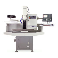
Tormach PCNC 770 Operator's Manual (230 pages)
Benchtop CNC Milling Machine
Brand:
Tormach
| Category:
Power Tool
| Size: 15 MB
Table of Contents
Operation
2
Electrical Safety
4
Table of Contents
9
Specifications (PCNC 770)
21
Site Planning and Prep
22
Ground Fault Interrupter (GFI) Use
23
Installation
24
Initial Uncrating
25
Remove Tool Tray (PCNC 1100 Only)
26
Lift and Move Mill
27
Remove Mill from Pallet
27
Lifting Bar Kit
27
Lifting from below
27
Moving Kit (PCNC 770 Only)
28
Lowering Mill Onto Stand
28
Install Tool Tray (PCNC 1100 Only)
28
Install Drip Tray
28
Install Pathpilot Controller
29
Installation of Add-Ons
31
Stand
31
Machine Arm
31
Mouse, Keyboard, and Jog Shuttle
31
USB Bulkhead Port
31
Manual or Automatic Oiler
31
Coolant System
31
Essential Controls Overview
32
E-Stop, Start, Reset, and Power
32
Power Off/Power on Procedure
33
Initial Pathpilot Controller Configuration
34
Validate Basic Installation
34
Verify Spindle Function
34
Verify Limit Switch Function
35
Verify Axis Function
36
Coolant On/Off
36
Installation Troubleshooting
36
Controller Customization
37
Operation
38
Control Locations
38
Operator Panel
38
Pathpilot Interface
38
Initializing the Mill
39
Vital Reference
39
Jogging
39
Manual Control Group
39
Spindle Controls
40
Manual Spindle Control Via Operator Panel
40
Automated Spindle Control Via Pathpilot Interface
41
Changing Spindle Speed Range
41
Tool Holders
42
Part Setup/Workholding
43
Intro to Pathpilot
44
Making Your First Part
44
Referencing the Mill
44
Workpiece Preparation
45
Tooling Preparation
45
Mill Position, Work Offsets and Tool Offsets
45
Setting Work Offset by Touching off Workpiece
46
Setting Tool Length Offset by Touching off Workpiece
48
Writing the G-Code
49
Operation
49
Operation 2
51
Pathpilot Interface
53
Overall Layout
53
Persistent Controls
54
Program Control Group
54
Position Status Group
56
Manual Control Group
57
Keyboard Shortcuts
60
Main Tab
60
File Tab
64
Settings Tab
65
Offsets Tab
68
Tool Tab
68
Automated Measurement with an Electronic Tool Setter
69
Offline Measurement with Height Gauge
69
Measurement by Touching off Tool
70
Offsets Table
70
Tool Offset and Fixture Information Backup
70
Work Tab
70
Conversational Tab
71
Face Tab
71
Profile Tab
72
Pocket Tab
73
Rectangular
73
Circular
75
Drill/Tap Tab
76
Drill
78
Tap
79
Thread Mill Tab
80
Engrave Tab
82
Probe Tab
84
XYZ Probe Tab
84
Rect/Circ Tab
85
Probe/Ets Setup Tab
86
ADMIN Commands
86
Programming
87
Definitions
87
G-Code Programming Language
90
Overview
90
Block
90
Real Value
90
Number
90
Formatting G-Code Blocks
91
Optional Program Stop Control - (M01 BREAK)
94
Additional G-Code Formatting Notes
94
Repeated Items
94
Order of Execution
94
Error Handling
96
Modality and Modal Commands
96
Modal Groups
96
Default Modes
97
G-Codes
97
Rapid Linear Motion - G00
99
Linear Motion at Feed Rate - G01
100
Arc at Feed Rate - G02 and G03
101
Radius Format Arc
101
Center Format Arc
102
Dwell - G04
105
Set Offsets - G10
105
Set Tool Table - G10 L1
105
Set Coordinate System - G10 L2
106
Set Tool Table - G10 L10
106
Set Tool Table - G10 L11
107
Set Coordinate System - G10 L20
107
Plane Selection - G17, G18 and G19
108
Return to Pre-Defined Position - G28 and G28.1
108
Return to Pre-Defined Position - G30 and G30.1
109
Straight Probe - G38
109
Using the Straight Probe Command
110
Cutter Compensation
111
Dynamic Cutter Compensation - G41.1, G42.1
112
Apply Tool Length Offset - G43
112
Engrave Sequential Serial Number - G47
113
G49 Cancel Tool Length Compensation - G49
113
Absolute Coordinates - G53
114
Select Work Offset Coordinate System - G54 to G59.3
114
Set Exact Path Control Mode - G61
114
Set Blended Path Control Mode - G64
115
Canned Cycles
115
Preliminary Canned Cycle Motion
117
Canned Cycle - High Speed Peck Drill - G73
117
G80 Cycle
118
G81 Cycle
118
G82 Cycle
120
G83 Cycle
121
G85 Cycle - Boring Cycle (Feed Rate Out)
121
G88 Cycle - Boring Cycle (Dwell, Manual Out)
122
G89 Cycle - Boring Cycle (Dwell, Feed Rate Out)
122
Arc Distance Mode - G90.1, G91.1
123
Distance Mode - G90 and G91
123
Temporary Work Offsets - G92, G92.1, G92.2 and G92.3
123
Feed Rate Mode - G93, G94 and G95
124
Spindle Control Mode
125
Built-In M-Codes
125
Program Stop and Program End - M00, M01, M02 and M30
126
Spindle Control - M03, M04 and M05
127
Tool Change - M06
127
Coolant Control - M07, M08 and M09
127
Override Control - M48 and M49
128
Feed Override Control - M50
128
Spindle Speed Override Control - M51
128
Set Output State
128
Wait on Input - M66
130
Operator Defined Commands - M100 to M199
130
Other Input Codes
131
Feed Rate - F
131
Spindle Speed - S
131
Change Tool Number - T
131
Advanced Programming with Parameters and Expressions
131
Parameters
131
Numbered Parameters
133
Parameter Types
133
Subroutine Parameters
134
Expressions
135
Named Parameters
135
Binary Operators
136
Functions
137
Programming with Subroutines
137
Subroutine Labels and Subroutine Keywords
137
Defining a Subroutine
138
Calling a Subroutine
139
Conditional Subroutines
140
Repeating Subroutines
140
Looping Subroutines
141
Accessories
143
4Th Axis Kits
143
Enclosures, Stands, and Machine Arms
145
Tapping Options
146
Oil and Coolant System Options
147
Automatic Oiler
147
Spray Coolant
147
Chip Flap Kit
147
Coolant Hose and Accessories
148
Tramp Oil Pillow
148
Spindle Options
148
High Speed Spindle Options
148
High-Speed Spindle
149
Kress Companion Spindle Kit
149
Tormach Speeder
149
Other Spindle Options
149
BT30 Spindle Cartridge
149
LED Spindle Light
150
Spindle Load Meter
150
Power Drawbar and ATC
150
Power Drawbar
150
Automatic Tool Changer (ATC)
151
Auxiliary Electronic Options
151
External Contactor Kit
151
Switchable Convenience Outlet Kit
152
USB M-Code I/O Interface Kit
152
Integrated Remote E-Stop Kit
152
Controller Options
152
USB Bulkhead Port Assembly
152
Prototyping Accessories
153
Injection Molder
153
CNC Scanner
153
Probe
154
Calibrating Probe Tip
155
Measuring Probe Tip Diameter
157
Tool Setter
157
Tool Setter Trigger Height
157
Maintenance
158
Regular Maintenance
158
Rust Prevention
159
Way Covers
159
Flood Coolant System
159
Lubrication System
160
Manual Pump Specifics
160
Drawbar and TTS Collet
161
Spindle Belt
161
Advanced Maintenance
162
Overview
162
Definitions
162
How to Measure Lost Motion
163
Gib Adjustment
164
Overview
164
Adjustment Procedure
165
Angular Contact Bearing Preload Adjustment
166
Overview
166
Adjustment Procedure
168
Determining Proper Angular Contact Bearing Preload
168
Geometry Adjustment of Precision Mating Surfaces
169
Spindle Bearing Adjustment
170
Spindle Calibration
170
Mill Transportation
172
Troubleshooting
173
Troubleshooting Basics
173
Tips and Tools for Troubleshooting (Equipment and Procedures)
175
Safety
175
Tips on Controller Diagnostics
175
Troubleshooting Tools
175
Using Digital Multimeter for Electrical Tests
176
Measuring DC Voltage
176
Measuring AC Voltage
176
Measuring Resistance
176
Contacting Technical Support
176
Frequently Found Problems
177
Loose Wires
177
Wire Hairs
178
Poor Cable Connections
178
Sensors (Limit Switches)
178
Unexplained Stop or Limit Switch Error While Running
178
Electrical Maintenance
178
Electrical Service
178
System Troubleshooting
179
Power Distribution Subsystem
181
Overview
181
Details of Power Distribution Subsystem
184
Control Power Subsystem
185
Details of Control Power Subsystem
187
Controller Communication Subsystem
188
Details on Controller Communication Subsystem
188
Overview
188
Axes Drive Subsystem
190
Overview of Axis Drive Subsystem
190
Details of Axis Drive Subsystem
202
Spindle Drive Subsystem
206
Overview
206
Diagrams and Parts List
217
Upper Mill Assembly (Exploded View)
217
Lower Mill Assembly (Exploded View)
220
Electrical Cabinet
222
Connections
224
Stepper Connection
225
Operator Panel
226
Ribbon Cable and Miscellaneous
227
Lubrication System
229
Advertisement
Tormach PCNC 770 Assembly Manual (13 pages)
Brand:
Tormach
| Category:
Industrial Equipment
| Size: 1 MB
Table of Contents
Table of Contents
2
Getting Started
3
Receiving the Stand
4
Attach the Feet to the Stand
5
Lift the Mill on to the Stand
7
Bolt the PCNC on the Stand
7
Installing Oil Pump
7
Attach the Coolant Trays
8
Installing Back Splash
9
Coolant System Installation
9
Machine Arm
12
Tormach PCNC 770 Quick Start Manual (4 pages)
CNC Scanner
Brand:
Tormach
| Category:
Control Systems
| Size: 1 MB
Table of Contents
Download and Install the Software
1
Activate the Software in Mach3
1
Install the Camera Driver
1
Setup up Scan Parameters
2
Taking Your First Scan
2
Align the Scope and Focus
2
Set the Start Point
3
Scale by Motion
3
Complete the Scan
4
Analyze Results
4
Advertisement
Tormach PCNC 770 Technical Document (5 pages)
Stand Assembly
Brand:
Tormach
| Category:
Racks & Stands
| Size: 0 MB
Table of Contents
PCNC 770 Stand Assembly
1
Required Tools
2
Receiving Stand
2
Attaching Feet to Stand
2
Foot Assembly
3
Lifting Mill Onto Stand
4
Installing Manual Oiler (Optional)
4
Installing Chip Pans
5
Advertisement
Related Products
Tormach PCNC 1100
Tormach PN 35927
Tormach PathPilot 1100M+
Tormach PCNC 440
Tormach PCNC 1100 Deluxe Stand
Tormach PCNC1100
Tormach PCNC Machine Arm
Tormach pathpilot
Tormach PSG 612
Tormach PATHPILOT OPERATOR CONSOLE
Tormach Categories
Industrial Equipment
Power Tool
Enclosure
Racks & Stands
Lathe
More Tormach Manuals
Login
Sign In
OR
Sign in with Facebook
Sign in with Google
Upload manual
Upload from disk
Upload from URL