Table of Contents

Related Manuals for Tormach PCNC 1100 Deluxe Stand


Summary of Contents for Tormach PCNC 1100 Deluxe Stand
- Page 1 Tormach® PCNC 1100 Deluxe Stand Tormach® PCNC Machine Arm Assembly Manual © 2011 Tormach® LLC. All rights reserved. Questions or comments? PCNC 1100 Deluxe Stand Please email us at: Manual info@tormach.com Part Number 32352, Rev. 1...
-
Page 2: Table Of Contents
Attaching the Splash Guard ........................11 Attaching the Lubrication Pump ......................12 10 Attaching the Machine Arm ........................13 *For a slideshow of the PCNC 1100 Deluxe Stand assembly, please visit: www.tormach.com 32352 Rev 1 Tormach® PCNC 1100 Deluxe Stand... -
Page 3: Getting Started
Gather all the appropriate tools. • Add silicone caulk to seams and bolt holes. Let the silicone caulk cure before removing the excess. • It is best if two people to assemble the stand. 32352 Rev 1 Tormach® PCNC 1100 Deluxe Stand... -
Page 4: Receiving The Stand
Parts stored in coolant tank. Next, with 2 people turn the base on its side. Then unbolt the base from the pallet as shown in Figure 3. Figure 3. Base on side to remove pallet. 32352 Rev 1 Tormach® PCNC 1100 Deluxe Stand... -
Page 5: Attaching The Feet To The Base
Figure 6. Foot parts In this case level the stand once it is in its final position. 32352 Rev 1 Tormach® PCNC 1100 Deluxe Stand... -
Page 6: Lifting The Mill On To The Base
Next carefully lift the mill onto the base. Tormach recommends using the Lifting Bar (PN 31446) with a crane or engine hoist, or place bars through the machine base and use a forklift Figure 7. -
Page 7: Bolting The Pcnc To The Base
Prior to attaching the tray to the base with the mounting bolts apply a small amount of silicone caulk to each bolt hole as shown in Figure 13. Figure 12. Setting coolant tray in place. 32352 Rev 1 Tormach® PCNC 1100 Deluxe Stand... - Page 8 The final step in the coolant tray installation is to install the back splash guards. Locate the back splash guards and test fit them to the coolant trays as shown in Figure 17. Figure 15. Stainless steel wear guard. 32352 Rev 1 Tormach® PCNC 1100 Deluxe Stand...
- Page 9 Caulking is not recommended for the joint between the splash guards and the coolant tray. Figure 16. Front wear guard parts Figure 17. Splash guard installation. Figure 18. Coolant tube inserted in base. 32352 Rev 1 Tormach® PCNC 1100 Deluxe Stand...
-
Page 10: Installing The Coolant System
Screws (8) to fix the Support (5) to the Mill Head (9). Finally tighten the Screw (7)to fix the Connecting Tube (4). The completed assembly is shown in Figure 21. Figure 21. Completed coolant tube assembly. 32352 Rev 1 Tormach® PCNC 1100 Deluxe Stand... -
Page 11: Attaching The Splash Guard
Figure 24. Finally slide the clear front view screen into the slots on the front of the guard as shown in Figure 22. Figure 23. Table mounted splash guard parts. Figure 24. Mounting guard to table. 32352 Rev 1 Tormach® PCNC 1100 Deluxe Stand... -
Page 12: Attaching The Lubrication Pump
The owner will need to drill and tap these on their own. The pump (5) should sit about 6 inches below the underside of the left coolant tray (1).] 32352 Rev 1 Tormach® PCNC 1100 Deluxe Stand... -
Page 13: Attaching The Machine Arm
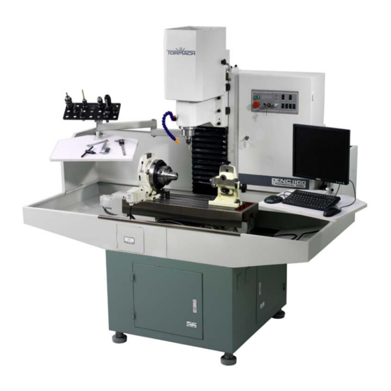
Figure 29 shows a machine with both arms in the suggested configuration. Figure 28. The machine arm configured for use with a monitor. 32352 Rev 1 Tormach® PCNC 1100 Deluxe Stand... - Page 14 Attaching the Machine Arm Figure 29. Machine arms in suggested configuration with separately purchased tooling, vice and computer. 32352 Rev 1 Tormach® PCNC 1100 Deluxe Stand...
- Page 15 In the coolant tank Adjustable Plastic Coolant In the coolant tank Tube Metal Flexible Tube In the coolant tank In the coolant tank Screw M5x20 Fixing Screw M6 x 12 In the coolant tank 32352 Rev 1 Tormach® PCNC 1100 Deluxe Stand...
- Page 16 In the coolant tank Rubber washer In the coolant tank Flat Washer 6 In the coolant tank Cross recess panhead screw In the coolant tank M5×8 Left Splash Guard Right Splash Guard 32352 Rev 1 Tormach® PCNC 1100 Deluxe Stand...
Need help?
Do you have a question about the PCNC 1100 Deluxe Stand and is the answer not in the manual?
Questions and answers