Table of Contents
Advertisement
Quick Links
FEATURES
• 1/2.5" 8 MegaPixel [4K] Progressive Scan CMOS image sensor
• High Definition Analog (HDA) / HD-TVI / AHD / HD-CVI / CVBS
• 8MP@15fps, 5MP@20fps, 4MP@30fps High Res, True Color
• Supports OSD Menu
• 2.8mm Fixed Iris Lens
• 1 Matrix IR with up to 100' IR Range (VTC-THB8R2,
VTC-THT8R2)
• 16 SMD IR LEDs with up to 65' Range (VTD-THD8R2)
• Digital Wide Dynamic Range D-WDR
• True Mechanical Day/Night function by ICR
• XD-DNR Noise Reduction
• Supsports Control over COAX (CoC)
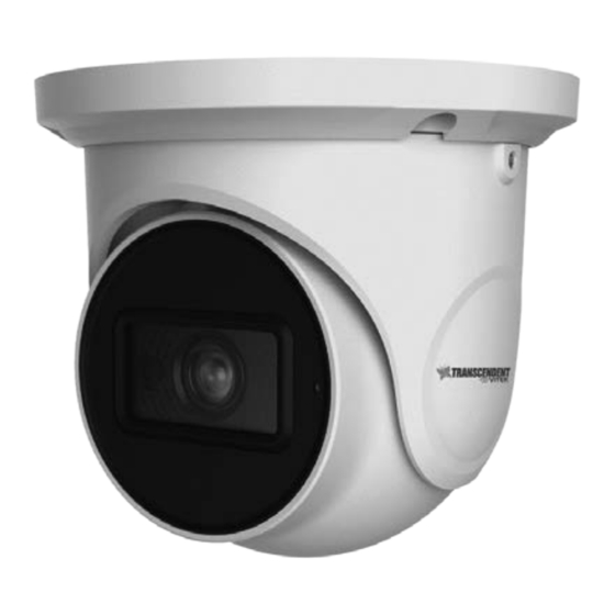
Transcendent 8.0 Megapixel [4K] Indoor/Outdoor
4-in-1 Fixed Lens Cameras
• IP67 Weather Resistance (+IK10 on VTD-THD8R2)
• Over 1500' HD Video Transmission (Depending on cable
characteristics and integrity)
• VTC-THB82: Optional J Box TJB08
• VTC-THT8R2: Optional J Boxes VT-TJB01, TJB08,
Wall Mount VT-TWMT-3
• VTD-THD8R2: Optional J Box VT-TJB03A, Wall Mount
VT-TWMT-3, In-ceiling Semi Flush Mount VT-TFMT-S
•
12VDC Operation
•
3-year Warranty
VTC-THB8R2
VTC-THT8R2
VTD-THD8R2
Advertisement
Table of Contents

Related Manuals for Vitek Transcendent VTC-THB8R2


Summary of Contents for Vitek Transcendent VTC-THB8R2
- Page 1 VTC-THB8R2 VTC-THT8R2 VTD-THD8R2 Transcendent 8.0 Megapixel [4K] Indoor/Outdoor 4-in-1 Fixed Lens Cameras FEATURES • 1/2.5” 8 MegaPixel [4K] Progressive Scan CMOS image sensor • IP67 Weather Resistance (+IK10 on VTD-THD8R2) • High Definition Analog (HDA) / HD-TVI / AHD / HD-CVI / CVBS •...
-
Page 2: Safety Precaution
Safety Precaution To prevent electrical shock and risk of fire hazards, do not expose this unit to rain or moisture and only use specified power source.. CAUTION: TO REDUCE THE RISK OF ELECTICAL SHOCK, DO NOT REMOVE COVER (OR BACK). NO USER SERVICEABLE PARTS INSIDE. -
Page 3: Video Connection
VTC-THB8R2 Components Video Connection Connect the BNC video connector to a BNC cable, then to a DVR. Camera Screws Monitor User Manual Drill Template Overview Video Video Output Mode Switch: This series supports AHD/TVI/CVI/CVBS video output. The video output can be changed by pressing and holding the button in the video switch cable for 5 seconds (the default video output is TVI video output). -
Page 4: Installation
Installation 2. Route the cables and connect the power & video cables, use the rubber plug to fill the gap of the mounting base. then secure the Before you begin, please make sure that the wall or ceiling is strong mounting base to the ceiling or wall with screws. - Page 5 VTC-THT8R2 Components Video Connection Connect the BNC video connector to a BNC cable, then to a DVR. Monitor Camera Hex Wrench Manual Mounting Plate Screws Rubber Plug Overview Video Video Output Mode Switch: This series supports AHD/TVI/CVI/CVBS video output. The video output can be changed by pressing and holding the button in the video switch cable for 5 seconds (the default video output is TVI video output).
- Page 6 Installation Before you begin, please make sure that the wall or ceiling is strong 4. Tighten the lock screws to secure the viewing angle adjustments. enough to withstand 3 times the weight of the camera. The mounting steps are as follows: 1.
- Page 7 Video Connection VTD-THD8R2 Components Connect the BNC video connector to a BNC cable, then to a DVR. Monitor Camera Screws Manual Allen Key Drill Template Video Overview Video Output Mode Switch: Video Switch Cable This series supports TVI/AHD/CVI/CVBS video output. Before switching video outputs, please remove the cover of the video switch cable.
- Page 8 Installation 4. Adjust the Three-axis camer bracket to obtain the optimium viewing angle. Before beginning installation, make sure that the wall or ceiling is strong enough to withstand 3 times the weight of the camera. The mounting steps are as follows: 2.92 INCHES 74.3...
-
Page 9: Camera Osd Menu
Camera OSD Menu The Transcendent 4-in1 camera series must be connected to a DVR which supports HD-TVI/AHD video signal input and COC protocol to access the OSD setup menu. Different DVRs manufacturers may have different modes of menu operation. The Following image will pop-up when you left click once on the image when using Different DVR manufacturers. - Page 10 Detailed Specifications VTC-THB8R2 VTC-THT8R2 VTD-THD8R2 1/2.5” 8.0 Megapixel Progressive Scan CMOS Sensor Image Sensor Signal System PAL/NTSC 3840 x 2160 Effective Pixels HD-TVI & AHD: 8.0 MegaPixel / CVI: 4.0 MegaPixel / CVBS: 960H Resolution HD-TVI / AHD / CVI / CVBS (Selectable) Video Output Frame Rate 8MP@15fps / 5MP@20fps / 4MP@30fps...
- Page 11 CONSIDER THESE OTHER GREAT TRANSCENDENT PRODUCTS! VT-TR4K VT-TR4VPK Passive Video Balun Video and Transmitter / Power Balun Pair with VITEK Transcendent Receiver Pair for Transmitter / Reciver Series 5-in-1 Digital Video Recorders Pair for HD-TVI / HDI-TVI / AHD / CVI...
-
Page 12: Limited Product Warranty
Limited Product Warranty VITEK products carry a three (3) year limited warranty. VITEK warrants to the purchaser that products manufactured by VITEK are free of any rightful claim of infringement or the like, and when used in the manner intended,...
Need help?
Do you have a question about the Transcendent VTC-THB8R2 and is the answer not in the manual?
Questions and answers