Table of Contents
Advertisement
Quick Links
• 1/2.7" 5.0 MegaPixel Progressive Scan CMOS Image Sensor
• High Definition Analog (HDA): HD-TVI / AHD: 5.0MP /
HD-CVI: 4.0MP / CVBS: 960H Video Output
• 2.8~12mm Motorized Varifocal Lens
• Supports OSD Menu
• Matrix IR with up to 165' IR Range (VTC-THB5RM)
• Matrix IR with up to 165' IR Range (VTC-THT5RM)
• Matrix IR with up to 100' IR Range (VTD-THD5RM)
• True Mechanical Day/Night function by ICR
• Digital Wide Dynamic Range (D-WDR)
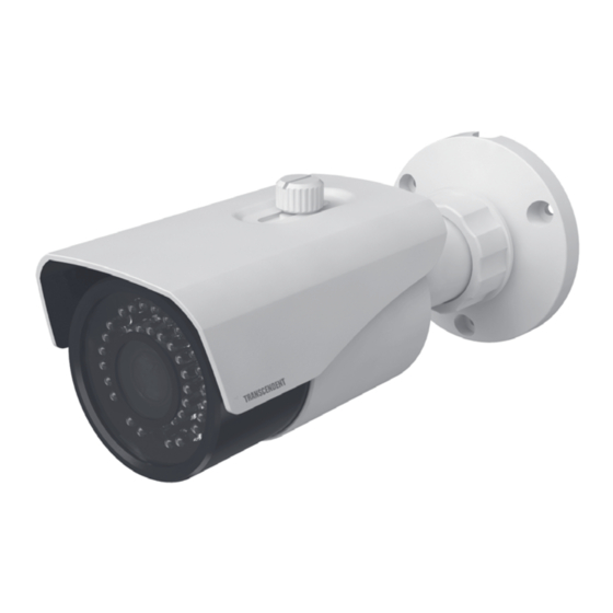
VTC-THB5RM
VTC-THT5RM
VTD-THD5RM
Transcendent 5.0 Megapixel Indoor/Outdoor
4-in-1 Motorized Lens Cameras
* VTC-THT5RM, and VTD-THD5RM available in ivory or charcoal
(VTC-THT5RMB, VTD-THD5RMB)
• Digital Noise Reduction (DNR)
• IP67 Weather Resistance (+IK10 on VTD-THD5RM)
• Supports Control over COAX (CoC)
• Over 1500' HD Video Transmission (Depending on cable
characteristics and integrity)
• Optional Mounts and Adapters Available
(see rear page)
•
12VDC Operation
•
3-year Warranty
Advertisement
Table of Contents

Related Manuals for Vitek Transcendent VTC-THB5RM


Summary of Contents for Vitek Transcendent VTC-THB5RM
- Page 1 VTC-THB5RM VTC-THT5RM VTD-THD5RM Transcendent 5.0 Megapixel Indoor/Outdoor 4-in-1 Motorized Lens Cameras * VTC-THT5RM, and VTD-THD5RM available in ivory or charcoal (VTC-THT5RMB, VTD-THD5RMB) • 1/2.7” 5.0 MegaPixel Progressive Scan CMOS Image Sensor • Digital Noise Reduction (DNR) • High Definition Analog (HDA): HD-TVI / AHD: 5.0MP / •...
-
Page 2: Safety Precautions
Safety Precautions To prevent electrical shock and risk of fire hazards, do not expose this unit VITEK products carry a three (3) year limited warranty. VITEK warrants to to rain or moisture and only use specified power source. the purchaser that products manufactured by VITEK are free of any rightful... -
Page 3: Video Connection
Video Connection VTC-THB5RM - Components Connect the BNC video connector to a BNC cable, then to a DVR. Monitor Camera Screws Manual Allen Key Drill Template Video Overview Video Output Mode Switch: Video Switch Cable This series supports TVI/AHD/CVI/CVBS video output. Before switching video outputs, please remove the cover of the video switch cable. -
Page 4: Installation
2. Route the cables and connect the power & video cables, use the Installation rubber plug to fill the gap of the mounting base, then secure the Before beginning installation, make mounting base to the ceiling or wall with screws. sure that the wall or ceiling is strong enough to withstand 3 times the weight of the camera. - Page 5 VTC-THT5RM Components Video Connection Connect the BNC video connector to a BNC cable, then to a DVR. Monitor Camera Allen Key Manual Mounting Plate Screws Rubber Plug Overview Video Video Output Mode Switch: Video Switch Cable This series supports TVI/AHD/CVI/CVBS video output. Before switching video outputs, please remove the cover of the video switch cable.
- Page 6 Installation Before you begin, please make sure that the wall or ceiling is strong 4. Tighten the lock screws to secure the viewing angle adjustments. enough to withstand 3 times the weight of the camera. The mounting steps are as follows: 1.
- Page 7 Video Connection VTD-THD5RM Components Connect the BNC video connector to a BNC cable, then to a DVR. Monitor Camera Screws Manual Allen Key Drill Template Video Overview Video Output Mode Switch: Video Switch Cable This series supports TVI/AHD/CVI/CVBS video output. Before switching video outputs, please remove the cover of the video switch cable.
- Page 8 Installation Before beginning installation, make sure that the wall or ceiling is 4. Adjust the Three-axis camera bracket to obtain the optimium strong enough to withstand 3 times the weight of the camera. The viewing angle. mounting steps are as follows: Pan: 0°~240°...
- Page 9 Adjusting the Motorized Lens 1. Click once on the image you want to adjust and then click on the PTZ icon on the sub toolbar 2. The PTZ screen will open and using the Zoom -/+ the lens in the camera will now Zoom in or out and will auto focus...
-
Page 10: Camera Osd Menu
Camera OSD Menu The Transcendent 4-in1 camera series must be connected to a DVR which supports HD-TVI/AHD video signal input and COC protocol to access the OSD setup menu. Different DVRs manufacturers may have different modes of menu operation. The Following image will pop-up when you left click once on the image when using Transcendent HDA DVR's. - Page 11 Detailed Specifications VTC-THB5RM VTC-THT5RM, VTC-THT5RMB VTD-THD5RM, VTD-THD5RMB Image Sensor 1/2.7” 5.0 Megapixel Progressive Scan CMOS Sensor Signal System PAL/NTSC Effective Pixels 2560 x 1936 Lorem ipsum Resolution HD-TVI & AHD: 5.0 MegaPixel / CVI: 4.0 MegaPixel / CVBS: 960H Video Output HD-TVI / AHD / CVI / CVBS (Selectable) Frame Rate 5MP@20fps, 4MP@30fps...
- Page 12 Pair for HD-TVI / AHD Pair for HD-TVI / AHD Select Transcen- Adapter (requires Adapter (requires / CVI for Distances Up / CVI for Distances Up Pair with VITEK Transcendent dent Motorized VT-TJB08 (for VT-TJB08 (for to 1440’ to 1000’ Domes (requires...
Need help?
Do you have a question about the Transcendent VTC-THB5RM and is the answer not in the manual?
Questions and answers