Table of Contents
Advertisement
Quick Links
FEATURES
• 1/2.8" 2.1 Megapixel Progressive Scan CMOS
Sensor
• 2.1 MegaPixel High Definition Analog (HDA):
HD-TVI , AHD, CVI / 960H: CVBS: Output
• 3.6mm Fixed Lens
• Infrared LED's with up to 120' IR Range
• True Wide Dynamic Range (WDR)
• True Mechanical Day/Night function by ICR
• 3D-DNR Noise Reduction
VTC-THB36R2F
VTC-THT24R2F
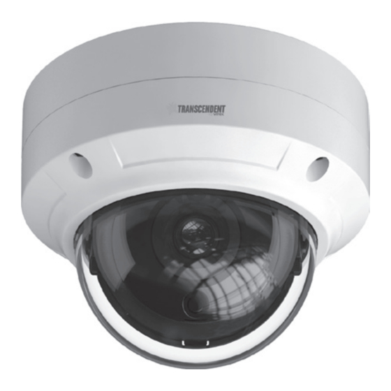
VTD-THD16R2F
Transcendent 2.1 Megapixel Indoor/
Outdoor 4-IN-1 HDA Cameras w/IR LED
• IP66 Weather Resistance & IK10 Impact Rating
• Supports Up The COAX Control
• Over 1500' HD Video Transmission (Depending on
cable characteristics and integrity)
• Optional Junction Box & Wall Mounts Available
• 12VDC Operation
• 3 Year Warranty
Illumination
Advertisement
Table of Contents

Related Manuals for Vitek Transcendent VTC-THB36R2F


Summary of Contents for Vitek Transcendent VTC-THB36R2F
- Page 1 VTC-THB36R2F VTC-THT24R2F VTD-THD16R2F Transcendent 2.1 Megapixel Indoor/ Outdoor 4-IN-1 HDA Cameras w/IR LED Illumination FEATURES • 1/2.8” 2.1 Megapixel Progressive Scan CMOS • IP66 Weather Resistance & IK10 Impact Rating Sensor • Supports Up The COAX Control • 2.1 MegaPixel High Definition Analog (HDA): •...
-
Page 2: Safety Precaution
Limited Product Warranty To prevent electrical shock and risk of fire hazards, do not expose this unit VITEK products carry a three (3) year limited warranty. VITEK warrants to to rain or moisture and only use specified power source.. the purchaser that products manufactured by VITEK are free of any rightful... -
Page 3: Video Connection
VTC-THB36R2F Components Video Connection Connect the BNC video connector to a BNC cable, then to a DVR. Camera Screws Monitor User Manual Drill Template Overview Video Video Output Mode Switch: Select the desired video mode using the dip switches contained within the on-cable Output Mode Switch as follows: HD-TVI CVBS... -
Page 4: Installation
Installation Before you begin, please make sure that the wall or ceiling is strong 3. Loosen the mount lock to adjust the Pan and Tilt of the camera, then enough to withstand 3 times the weight of the camera. The mounting tighten the mount lock to secure the viewing angle adjustments. - Page 5 VTC-THT24R2F Components Video Connection Connect the BNC video connector to a BNC cable, then to a DVR. Monitor Camera Hex Wrench Manual Mounting Plate Screws Rubber Plug Overview Video Video Output Mode Switch: Select the desired video mode using the dip switches contained within the on-cable Output Mode Switch as follows: HD-TVI CVBS...
- Page 6 Installation Before you begin, please make sure that the wall or ceiling is strong 4. Tighten the lock screws to secure the viewing angle adjustments. enough to withstand 3 times the weight of the camera. The mounting steps are as follows: 1.
- Page 7 Video Connection VTD-THD16R2F Components Connect the BNC video connector to a BNC cable, then to a DVR. Monitor Camera Screws Manual Hex Wrench Drill Template Overview Video Video Output Mode Switch: Select the desired video mode using the dip switches contained within the on-cable Output Mode Switch as follows: HD-TVI CVBS...
- Page 8 Installation Before beginning installation, make sure that the wall or ceiling is 4. Adjust the Three-axis camer bracket to obtain the optimium strong enough to withstand 3 times the weight of the camera. The viewing angle. mounting steps are as follows: 1.
-
Page 9: Camera Osd Menu
Camera OSD Menu The Transcendent 4-in1 camera series must be connected to a DVR which supports HD-TVI/AHD video signal input and COC protocol to access the OSD setup menu. Different DVRs manufacturers may have different modes of menu operation. The Following image will pop-up when you left click once on the image when using Transcendent HDA DVR's. - Page 10 Detailed Specifications VTC-THB36R2F VTC-THT24R2F VTD-THD16R2F Image Sensor 1/2.8” 2.1 Megapixel Progressive Scan CMOS Sensor Signal System PAL/NTSC Effective Pixels 1920 x 1080 Resolution HD-TVI / AHD / CVI: 2.1 MegaPixel / CVBS: 960H Video Output HD-TVI / AHD / CVI / CVBS (Selectable) Frame Rate 30fps Lens...
- Page 11 TRANSCENDENT MOUNTS ALSO AVAILABLE FOR 4-IN-1 CAMERAS! VT-TJB01 VT-TJB03A Optional Junction Box for Optional Junction Box for Cable Cable Management for use Management for use with Select with all Transcendent Bullet Transcendent Vandal Dome and Turret Style Cameras Cameras VT-TWMT3 Optional Wall Mount for use with most Transcendent Fixed Domes and Turrets.
- Page 12 Version 1.0 28492 CONSTELLATION ROAD VALENCIA, CA 91355 January 2018 WWW.VITEKCCTV.COM...
Need help?
Do you have a question about the Transcendent VTC-THB36R2F and is the answer not in the manual?
Questions and answers