
Related Manuals for Rohde & Schwarz FSVA3000


Summary of Contents for Rohde & Schwarz FSVA3000
- Page 1 ® ® R&S FSVA3000/ R&S FSV3000 Signal and Spectrum Analyzer User Manual (;ÜãD2) 1178852002 Version 08...
- Page 2 FSVA3000 is indicated as ® ® R&S FSVA3000. R&S FSV3000 is indicated as R&S FSV3000. R&S FSV/A refers to both the R&S FSV3000 and the R&S FSVA3000. Products of the R&S ® SMW family, e.g. R&S ® SMW200A, are indicated as R&S SMW.
-
Page 3: Table Of Contents
® ® Contents R&S FSVA3000/ R&S FSV3000 Contents 1 Safety and regulatory information............33 Safety Instructions......................33 Warning messages in the documentation..............35 Korea certification class A..................36 2 Documentation overview..............37 Getting started manual....................37 User manuals and help....................37 Service manual......................37 Instrument security procedures................38 Printed safety instructions..................38... - Page 4 ® ® Contents R&S FSVA3000/ R&S FSV3000 3.2.14 Considerations for test setup..................55 3.2.15 Protecting data using the secure user mode..............55 Instrument tour......................58 3.3.1 Front panel view......................58 3.3.1.1 Power key........................58 3.3.1.2 USB..........................59 3.3.1.3 System keys........................59 3.3.1.4 Touchscreen........................59 3.3.1.5 Function keys........................ 61 3.3.1.6...
- Page 5 ® ® Contents R&S FSVA3000/ R&S FSV3000 3.3.2.12 Aux. control........................69 3.3.2.13 External generator control option (R&S FSV3-B10)............70 3.3.2.14 OCXO option (R&S FSV3-B4)..................70 3.3.2.15 Labels on R&S FSV/A....................70 3.3.2.16 Device ID........................70 Trying out the instrument...................71 3.4.1 Measuring a basic signal....................71 3.4.2...
- Page 6 ® ® Contents R&S FSVA3000/ R&S FSV3000 3.5.5 Displaying results......................113 3.5.5.1 Activating and deactivating channels................113 3.5.5.2 Laying out the result display with the smartgrid............115 Background information: the smartgrid principle............116 How to activate smartgrid mode.................. 117 How to add a new result window................. 117 How to close a result window..................
- Page 7 ® ® Contents R&S FSVA3000/ R&S FSV3000 5.2.5.2 Measuring the modulation depth of an AM-modulated carrier in the frequency domain ............................ 148 5.2.5.3 Measuring AM-modulated signals................149 5.2.6 Measurement examples in zero span................. 151 5.2.6.1 Measuring the power characteristic of burst signals........... 151 Measuring the power of a GSM burst during the activation phase......
- Page 8 ® ® Contents R&S FSVA3000/ R&S FSV3000 5.3.6.2 How to set up the channels..................200 5.3.6.3 How to configure an MSR ACLR measurement............201 5.3.6.4 How to manage user-defined configurations...............203 5.3.6.5 How to compare the tx channel power in successive measurements......204 5.3.7 Measurement examples....................204...
- Page 9 ® ® Contents R&S FSVA3000/ R&S FSV3000 5.6.5 SEM configuration.......................239 5.6.5.1 Sweep List ........................240 5.6.5.2 Multi-sem (sub block) settings..................246 5.6.5.3 Reference range......................247 5.6.5.4 Power classes......................249 5.6.5.5 MSR settings.......................250 5.6.5.6 Standard files......................253 5.6.5.7 List evaluation (results configuration)................255 5.6.6 How to perform a spectrum emission mask measurement.........
- Page 10 ® ® Contents R&S FSVA3000/ R&S FSV3000 5.8.5.1 Basic settings......................288 5.8.5.2 Gate range definition for APD and CCDF..............290 5.8.5.3 Scaling for statistics diagrams..................291 5.8.6 How to perform an APD or CCDF measurement............294 5.8.7 Examples........................295 5.8.7.1 Configuration example: gated statistics..............295 5.8.7.2...
- Page 11 ® ® Contents R&S FSVA3000/ R&S FSV3000 5.12.5 How to determine the AM modulation depth............... 323 5.13 Electromagnetic interference (EMI) measurement..........323 5.13.1 About the EMI measurement..................324 5.13.2 EMI measurement results................... 325 5.13.3 EMI measurement basics....................326 5.13.3.1 Resolution bandwidth and filter types................. 326 5.13.3.2...
- Page 12 ® ® Contents R&S FSVA3000/ R&S FSV3000 6.2.3.1 Basics on power sensors.................... 362 Using a power sensor as an external power trigger............363 6.2.3.2 Power sensor settings....................364 6.2.3.3 How to work with a power sensor................368 How to set up a power sensor..................369 How to zero the power sensor..................
- Page 13 ® ® Contents R&S FSVA3000/ R&S FSV3000 External mixers and large bandwidth extension options..........401 Automatic signal identification..................403 6.2.5.2 External mixer settings....................407 Mixer settings......................407 Basic settings......................411 Managing conversion loss tables................413 Creating and editing conversion loss tables..............415 6.2.5.3 How to work with external mixers................418...
- Page 14 ® ® Contents R&S FSVA3000/ R&S FSV3000 6.3.3 Keeping the center frequency stable - signal tracking..........451 6.3.4 How to define the frequency range................452 6.3.5 How to move the center frequency through the frequency range....... 452 Amplitude and vertical axis configuration..............453 6.4.1...
- Page 15 ® ® Contents R&S FSVA3000/ R&S FSV3000 6.6.1.3 How to determine the required trigger/gate parameters..........490 6.6.1.4 How to configure a triggered measurement..............491 6.6.2 Gating..........................492 6.6.2.1 Gated measurements....................492 6.6.2.2 Gate settings....................... 494 6.6.2.3 Continuous gate settings.....................496 6.6.2.4 How to configure a gated measurement..............497 Adjusting settings automatically................498...
- Page 16 ® ® Contents R&S FSVA3000/ R&S FSV3000 7.3.4 Marker (measurement) functions................533 7.3.4.1 Precise frequency (signal count) marker..............533 7.3.4.2 Measuring noise density (noise meas marker)............535 7.3.4.3 Phase noise measurement marker................538 7.3.4.4 Measuring characteristic bandwidths (n db down marker)..........541 7.3.4.5...
- Page 17 ® ® Contents R&S FSVA3000/ R&S FSV3000 Analyzing several traces - trace mode................ 582 How many traces are averaged - sweep count + Sweep mode........583 How trace data is averaged - the averaging mode............. 584 Trace smoothing......................585 7.5.1.2 Trace settings......................586 7.5.1.3...
- Page 18 ® ® Contents R&S FSVA3000/ R&S FSV3000 9 Data management................634 Restoring the default instrument configuration (preset)........634 Protecting data using the secure user mode............635 Storing and recalling instrument settings and measurement data...... 637 9.3.1 Quick save/quick recall....................639 9.3.1.1 Quick save / quick recall settings................
- Page 19 ® ® Contents R&S FSVA3000/ R&S FSV3000 10.1 Alignment........................684 10.1.1 Basics on alignment....................684 10.1.2 Alignment settings.......................686 10.1.3 How to perform a self-test................... 690 10.1.4 How to align the instrument..................690 10.1.5 How to align the touchscreen..................691 10.2 Display settings......................691 10.2.1 Display settings......................
- Page 20 ® ® Contents R&S FSVA3000/ R&S FSV3000 10.8.2.1 Obtaining copyright information on used third-party sources........740 10.8.2.2 License management....................741 10.8.3 System messages.......................745 10.8.4 Firmware updates....................... 746 10.8.5 General configuration settings..................748 10.8.6 Signal generator settings.................... 750 10.9 Service functions...................... 751 10.9.1 R&S support information.....................
- Page 21 ® ® Contents R&S FSVA3000/ R&S FSV3000 11.2.2.9 STATus:QUEStionable:FREQuency register...............785 11.2.2.10 STATus:QUEStionable:LIMit register................786 11.2.2.11 STATus:QUEStionable:LMARgin register..............786 11.2.2.12 STATus:QUEStionable:POWer register..............787 11.2.2.13 STATus:QUEStionable:TEMPerature register.............788 11.2.2.14 STATus:QUEStionable:TIMe register................788 11.2.3 Reset values of the status reporting system............... 789 11.3 GPIB languages......................790 11.4...
- Page 22 ® ® Contents R&S FSVA3000/ R&S FSV3000 11.7.1.5 How to change the GPIB instrument address............. 830 11.7.2 How to operate the instrument without a network............830 11.7.3 How to log on to the network..................830 11.7.3.1 How to create users....................831 11.7.3.2...
- Page 23 ® ® Contents R&S FSVA3000/ R&S FSV3000 12.5.3.6 General ACLR measurement settings................ 881 12.5.3.7 Configuring MSR ACLR measurements..............882 General MSR ACLR measurement settings............... 882 MSR sub block and tx channel setup................883 MSR adjacent channel setup..................885 General gap channel setup..................890 Automatic (symmetrical) configuration................
- Page 24 ® ® Contents R&S FSVA3000/ R&S FSV3000 12.5.7.2 Configuring a sweep list....................963 12.5.7.3 Configuring the list evaluation..................972 12.5.7.4 Adjusting the X-axis to the range definitions............... 974 12.5.7.5 Performing a spurious measurement................974 12.5.7.6 Retrieving and saving settings and results..............974 12.5.7.7...
- Page 25 ® ® Contents R&S FSVA3000/ R&S FSV3000 12.5.12.1 Configuring and performing the measurement............1004 12.5.12.2 Example: measuring the AM modulation depth............1005 12.5.13 Remote commands for EMI measurements..............1006 12.5.13.1 Activating EMI measurement..................1006 12.5.13.2 Configuring EMI markers..................1007 12.5.13.3 Configuring the EMI final test..................1008 12.5.13.4...
- Page 26 ® ® Contents R&S FSVA3000/ R&S FSV3000 Mixer settings......................1057 Conversion loss table settings.................. 1064 Programming example: working with an external mixer..........1068 12.7.1.4 Setting up probes...................... 1070 12.7.1.5 External generator control..................1075 Measurement configuration..................1076 Interface configuration....................1079 Source calibration..................... 1081 Programming example for external generator control..........1084 12.7.1.6...
- Page 27 ® ® Contents R&S FSVA3000/ R&S FSV3000 12.8.1.2 Using the multiple zoom.................... 1142 12.8.2 Configuring the trace display and retrieving trace data..........1143 12.8.2.1 Configuring standard traces..................1144 12.8.2.2 Configuring spectrograms..................1151 Configuring a spectrogram measurement..............1151 Configuring the color map..................1157 12.8.2.3...
- Page 28 ® ® Contents R&S FSVA3000/ R&S FSV3000 Example: basic markers....................1222 Example: marker search in spectrograms..............1223 Basic frequency sweep measurement for marker function examples.......1224 Example: using a fixed reference marker..............1224 Example: obtaining a marker peak list..............1225 Example: measuring noise density................1225 Example: measuring phase noise................
- Page 29 ® ® Contents R&S FSVA3000/ R&S FSV3000 12.9.7.7 Storing multiple graphical measurement results to a PDF file........1289 12.10 Configuring the R&S FSV/A................... 1290 12.10.1 Configuring the reference frequency.................1290 12.10.2 Calibration and checks....................1293 12.10.3 Working with transducers..................1297 12.10.4 Compensating for frequency response using touchstone files (R&S FSV/A-K544)..1301 12.10.4.1...
- Page 30 ® ® Contents R&S FSVA3000/ R&S FSV3000 12.13.2 Reference: GPIB commands of emulated HP models..........1377 12.13.2.1 Command set of models 8560E, 8561E, 8562E, 8563E, 8564E, 8565E, 8566A/B, 8568A/B, 8591E, 8594E, 71100C, 71200C, and 71209A......... 1377 12.13.2.2 Special features of the syntax parsing algorithms for 8566A and 8568A models..1401 12.13.2.3...
- Page 31 ® ® Contents R&S FSVA3000/ R&S FSV3000 15 Maintenance, storage, transport and disposal......1437 15.1 Cleaning........................1437 15.2 Storage........................1437 15.3 Transporting......................1437 15.4 Disposal........................1438 List of remote commands (base unit)..........1439 Index....................1464 User Manual 1178.8520.02 ─ 08...
- Page 32 ® ® Contents R&S FSVA3000/ R&S FSV3000 User Manual 1178.8520.02 ─ 08...
-
Page 33: Safety And Regulatory Information
® ® Safety and regulatory information R&S FSVA3000/ R&S FSV3000 Safety Instructions 1 Safety and regulatory information The product documentation helps you use the product safely and efficiently. Follow the instructions provided here and in the following chapters. Intended use The product is intended for the development, production and verification of electronic components and devices in industrial, administrative, and laboratory environments. - Page 34 ® ® Safety and regulatory information R&S FSVA3000/ R&S FSV3000 Safety Instructions Choosing the operating site Only use the product indoors. The product casing is not waterproof. Water that enters can electrically connect the casing with live parts, which can lead to electric shock, serious personal injury or death if you touch the casing.
-
Page 35: Warning Messages In The Documentation
® ® Safety and regulatory information R&S FSVA3000/ R&S FSV3000 Warning messages in the documentation ● Only connect the product to a power source with a fuse protection of maximum 20 A. ● Ensure that you can disconnect the product from the power source at any time. -
Page 36: Korea Certification Class A
® ® Safety and regulatory information R&S FSVA3000/ R&S FSV3000 Korea certification class A NOTICE Potential risks of damage. Could result in damage to the supported product or to other property. 1.3 Korea certification class A 이 기기는 업무용(A급) 전자파 적합기기로서 판매자 또는 사용자는 이 점을 주의하시기... -
Page 37: Documentation Overview
® ® Documentation overview R&S FSVA3000/ R&S FSV3000 Service manual 2 Documentation overview This section provides an overview of the R&S FSV/A user documentation. Unless specified otherwise, you find the documents on the R&S FSV/A product page at: www.rohde-schwarz.com/product/FSVA3000.html/ www.rohde-schwarz.com/product/FSV3000.html 2.1 Getting started manual... -
Page 38: Instrument Security Procedures
Release notes and open-source acknowledgment (OSA) The service manual is available for registered users on the global Rohde & Schwarz information system (GLORIS): R&S®FSVA3000/FSV3000 Service manual 2.4 Instrument security procedures Deals with security issues when working with the R&S FSV/A in secure areas. It is available for download on the Internet. -
Page 39: Application Notes, Application Cards, White Papers, Etc
® ® Documentation overview R&S FSVA3000/ R&S FSV3000 Application notes, application cards, white papers, etc. 2.8 Application notes, application cards, white papers, etc. These documents deal with special applications or background information on particu- lar topics. www.rohde-schwarz.com/application/FSV3000 www.rohde-schwarz.com/application/FSVA3000 User Manual 1178.8520.02 ─ 08... -
Page 40: Getting Started
® ® Getting started R&S FSVA3000/ R&S FSV3000 3 Getting started Note: the following chapters are identical to those in the printed R&S FSV/A Getting Started manual. Key features.........................43 Preparing for use......................43 3.2.1 Lifting and carrying......................44 3.2.2 Unpacking and checking....................44 3.2.3... - Page 41 ® ® Getting started R&S FSVA3000/ R&S FSV3000 Undo/redo keys......................63 3.3.1.8 Trigger input / output..................... 64 3.3.1.9 RF input 50 ohm......................64 3.3.1.10 Probe..........................64 3.3.1.11 Ext mixer connector (optional)..................64 3.3.1.12 Noise source control / power sensor................65 3.3.1.13 AF out and volume (R&S FSV3-B3)................65 3.3.1.14...
- Page 42 ® ® Getting started R&S FSVA3000/ R&S FSV3000 3.4.8 Zooming into the display permanently................87 3.4.9 Saving settings......................90 3.4.10 Printing and saving results.................... 92 Operating the instrument................... 93 3.5.1 Understanding the display information................94 3.5.1.1 Channel bar........................95 3.5.1.2 Window title bar......................98 3.5.1.3...
-
Page 43: Key Features
Optional measurement applications for demodulation of analog and digital modula- ted signals For a detailed specification, refer to the data sheet. Due to these features, the R&S FSV3000 and the R&S FSVA3000 are ideal for various measurement tasks, for instance: ●... -
Page 44: Lifting And Carrying
® ® Getting started R&S FSVA3000/ R&S FSV3000 Preparing for use ● Logging on......................52 ● Checking the supplied options................54 ● Performing a self-alignment..................54 ● Considerations for test setup.................. 55 ● Protecting data using the secure user mode............55 3.2.1 Lifting and carrying... -
Page 45: Setting Up The R&S Fsv/A
® ® Getting started R&S FSVA3000/ R&S FSV3000 Preparing for use 3.2.4 Setting up the R&S FSV/A The R&S FSV/A is designed for use on a bench top or in a rack. See also: ● "Setting up the product" on page 34 ●... -
Page 46: Mounting The R&S Fsv/A In A Rack
® ® Getting started R&S FSVA3000/ R&S FSV3000 Preparing for use 3.2.4.2 Mounting the R&S FSV/A in a rack To prepare the rack 1. Observe the requirements and instructions in "Setting up the product" on page 34. 2. NOTICE! Insufficient airflow can cause overheating and damage the product. -
Page 47: Switching The Instrument On And Off
® ® Getting started R&S FSVA3000/ R&S FSV3000 Preparing for use 2. Plug the AC power cable into a power outlet with ground contact. The required ratings are listed next to the AC power connector and in the data sheet. -
Page 48: Connecting To Lan
® ® Getting started R&S FSVA3000/ R&S FSV3000 Preparing for use If the instrument temperature exceeds the limit specified in the data sheet, the R&S FSV/A automatically shuts down to protect the instrument from damage. To disconnect from power The R&S FSV/A is in the standby state. -
Page 49: Connecting A Keyboard
® ® Getting started R&S FSVA3000/ R&S FSV3000 Preparing for use ● Configuring the network ● Changing IP addresses ● Exchanging hardware Errors can affect the entire network. Connect the R&S FSV/A to the LAN via the LAN interface on the rear panel of the instrument. - Page 50 ® ® Getting started R&S FSVA3000/ R&S FSV3000 Preparing for use Screen resolution and format The touchscreen of the R&S FSV/A is calibrated for a 16:10 format. If you connect a monitor or projector using a different format (e.g. 4:3), the calibration is not correct and the screen does not react to your touch actions properly.
-
Page 51: Windows Operating System
® ® Getting started R&S FSVA3000/ R&S FSV3000 Preparing for use ● "Display 2": external monitor only ● "Duplicate": both internal and external monitor 6. Tap "Apply" to try out the settings before they are accepted permanently, then you can easily return to the previous settings, if necessary. -
Page 52: Logging On
® ® Getting started R&S FSVA3000/ R&S FSV3000 Preparing for use Virus protection Take appropriate steps to protect your instruments from infection. Use strong firewall settings and scan any removable storage device used with a Rohde & Schwarz instru- ment regularly. It is also recommended that you install anti-virus software on the instru- ment. - Page 53 ® ® Getting started R&S FSVA3000/ R&S FSV3000 Preparing for use Secure user mode If the secure user mode option (R&S FSV3-K33) is installed, an additional account is provided: the "SecureUser". The "SecureUser" is a standard user account with limited functionality. In particular, administrative tasks such as LAN configuration or general instrument settings are not available.
-
Page 54: Checking The Supplied Options
® ® Getting started R&S FSVA3000/ R&S FSV3000 Preparing for use 6. Enter the command C:\R_S\INSTR\USER\user\AUTOLOGIN.REG. 7. Press the [ENTER] key to confirm. The auto-login function is reactivated with the changed password. It will be applied the next time the instrument is switched on. -
Page 55: Considerations For Test Setup
® ® Getting started R&S FSVA3000/ R&S FSV3000 Preparing for use A message in the status bar ("Instrument warming up...") indicates that the operating temperature has not yet been reached. Depending on the installation settings, an automatic self-alignment is performed each time the instrument is switched on. - Page 56 ® ® Getting started R&S FSVA3000/ R&S FSV3000 Preparing for use Redirecting storage to volatile memory Alternatively, to avoid storing any sensitive data on the R&S FSV/A permanently, the secure user mode was introduced (option R&S FSV3-K33). In secure user mode, the instrument’s solid-state drive is write-protected so that no information can be written to...
- Page 57 ® ® Getting started R&S FSVA3000/ R&S FSV3000 Preparing for use Furthermore, since the "SecureUser" used in secure user mode does not have admin- istrator rights, administrative tasks such as LAN configuration and some general instrument settings are not available. Refer to the description of the basic instrument setup ([SETUP] menu) to find out which functions are affected.
-
Page 58: Instrument Tour
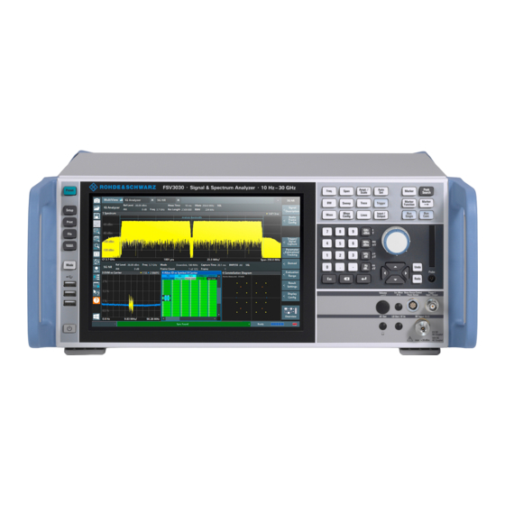
® ® Getting started R&S FSVA3000/ R&S FSV3000 Instrument tour 3.3 Instrument tour 3.3.1 Front panel view This chapter describes the front panel, including all function keys and connectors. Figure 3-1: Front panel view of R&S FSV/A 1 = POWER key... -
Page 59: Usb
® ® Getting started R&S FSVA3000/ R&S FSV3000 Instrument tour 3.3.1.2 The front panel provides three female USB connectors (USB-A) to connect devices like a keyboard or a mouse. In addition, a memory stick can be connected to store and reload instrument settings and measurement data. - Page 60 ® ® Getting started R&S FSVA3000/ R&S FSV3000 Instrument tour Figure 3-2: Touchscreen elements 1 = Toolbar with standard application functions, e.g. print, save/open file etc. 2 = Tabs for individual measurement channels 3 = Channel bar for firmware and measurement settings...
-
Page 61: Function Keys
® ® Getting started R&S FSVA3000/ R&S FSV3000 Instrument tour For details on touchscreen gestures, see Chapter 3.5.4, "Touchscreen gestures", on page 110. 3.3.1.5 Function keys Function keys provide access to the most common measurement settings and func- tions. A detailed description of the corresponding functions is provided in the user manual. -
Page 62: Removable Solid State Drive (Ssd)
® ® Getting started R&S FSVA3000/ R&S FSV3000 Instrument tour Function key Assigned functions [Marker ->] Used for search functions of the measurement markers (maximum/mini- mum of the trace). Assigns the marker frequency to the center frequency, and the marker level to the reference level. -
Page 63: Rotary Knob
® ® Getting started R&S FSVA3000/ R&S FSV3000 Instrument tour Navigating in tables The easiest way to navigate within tables (both in result tables and configuration tables) is to scroll through the entries with your finger on the touchscreen. Rotary knob The rotary knob has several functions: ●... -
Page 64: Trigger Input / Output
® ® Getting started R&S FSVA3000/ R&S FSV3000 Instrument tour ● The [Redo] key repeats the previously reverted action, i.e. the most recent action is repeated. The [Undo] function is not available after a [Preset] or "Recall" operation. When these functions are used, the history of previous actions is deleted. -
Page 65: Noise Source Control / Power Sensor
® ® Getting started R&S FSVA3000/ R&S FSV3000 Instrument tour If no external mixers are connected to the R&S FSV/A, cover the two front connectors Ext Mixer IF In and LO Out / IF In with the supplied SMA caps. -
Page 66: Rear Panel View
® ® Getting started R&S FSVA3000/ R&S FSV3000 Instrument tour Type of key Description [Esc] key Closes all kinds of dialog boxes, if the edit Mode is not active. Quits the edit mode, if the edit mode is active. In dialog boxes that contain a "Can- cel"... -
Page 67: Ac Power Supply Connection And Main Power Switch
® ® Getting started R&S FSVA3000/ R&S FSV3000 Instrument tour 9 = IEEE 488/ IEC625/ SCPI (GPIB) interface (requires option R&S FSV3-B5) 10 = Noise Source Control (requires option R&S FSV3-B28V) 11 = Trigger 2 (In/Out) connector 12 = REF In/Out connectors 13 = IF output connector (requires option R&S FSV3-B5) -
Page 68: Usb
® ® Getting started R&S FSVA3000/ R&S FSV3000 Instrument tour 3.3.2.4 The rear panel provides 2 additional female USB (USB-A) connectors to connect devi- ces like a keyboard, a mouse or a memory stick (see also Chapter 3.3.1.2, "USB", on page 59). -
Page 69: If Output
® ® Getting started R&S FSVA3000/ R&S FSV3000 Instrument tour Connector Reference signal Usage REF Input 1 1 MHz - 100 MHz (in To provide an external reference signal to the R&S FSV/A. 1 ppm steps) 0 dBm - 15 dBm... -
Page 70: External Generator Control Option (R&S Fsv3-B10)
® ® Getting started R&S FSVA3000/ R&S FSV3000 Instrument tour 3.3.2.13 External generator control option (R&S FSV3-B10) The external generator control option uses a LAN connection and the "AUX control" connector. For details on connecting an external generator, see the "External Generator Control"... -
Page 71: Trying Out The Instrument
® ® Getting started R&S FSVA3000/ R&S FSV3000 Trying out the instrument The serial number is used to define the default instrument name, which is: <Type><variant>-<serial_number> For example, FSV3004-123456. The instrument name is required to establish a connection to the instrument in a LAN. - Page 72 ® ® Getting started R&S FSVA3000/ R&S FSV3000 Trying out the instrument 5. Tap the "Calibration Frequency RF" option. Leave the frequency at the default 64 MHz, with a narrowband spectrum. The calibration signal is now sent to the RF input of the R&S FSV/A. By default, a continuous frequency sweep is performed, so that the spectrum of the calibration signal is now displayed in the standard level versus frequency diagram.
-
Page 73: Displaying A Spectrogram
® ® Getting started R&S FSVA3000/ R&S FSV3000 Trying out the instrument a) In the "Span" field of the "Frequency" dialog box, enter 20 MHz. b) Close the "Frequency" dialog box. The display of the calibration signal is now improved. The maximum at the center frequency (=calibration frequency) of 64 MHz becomes visible. - Page 74 ® ® Getting started R&S FSVA3000/ R&S FSV3000 Trying out the instrument Drag the "Spectrogram" icon from the evaluation bar to the diagram area. The blue area indicates that the new diagram would replace the previous spectrum display. Since we do not want to replace the spectrum, drag the icon to the lower half of the display to add an additional window instead.
-
Page 75: Activating Additional Measurement Channels
® ® Getting started R&S FSVA3000/ R&S FSV3000 Trying out the instrument Figure 3-7: Spectrogram of the calibration signal 3.4.3 Activating additional measurement channels The R&S FSV/A features multiple measurement channels, i.e. you can define several measurement configurations in parallel and then switch between the channels auto- matically to perform the measurements sequentially. - Page 76 ® ® Getting started R&S FSVA3000/ R&S FSV3000 Trying out the instrument Figure 3-8: Adding a new measurement channel 3. Change the frequency range for this spectrum display: In the "Frequency" dialog box, set the center frequency to 500 MHz and the span to 1 GHz.
- Page 77 ® ® Getting started R&S FSVA3000/ R&S FSV3000 Trying out the instrument Figure 3-9: Frequency spectrum of the calibration signal with a larger span 4. Repeat the previous steps to activate a third Spectrum window. Change the frequency range for this spectrum display: In the "Frequency"...
- Page 78 ® ® Getting started R&S FSVA3000/ R&S FSV3000 Trying out the instrument Figure 3-10: Time domain display of the calibration signal 5. Create a new channel for I/Q analysis: a) Press the [Mode] key. b) Tap the "IQ Analyzer" button to activate a channel for the I/Q Analyzer applica- tion.
- Page 79 ® ® Getting started R&S FSVA3000/ R&S FSV3000 Trying out the instrument d) Drag the "Real/Imag (I/Q)" icon from the evaluation bar to the SmartGrid. Figure 3-11: Inserting a Real/Imag diagram for I/Q analysis e) Close the SmartGrid mode. The "IQ Analyzer" channel displays the real and imaginary signal parts in separate windows.
-
Page 80: Performing Sequential Measurements
® ® Getting started R&S FSVA3000/ R&S FSV3000 Trying out the instrument Figure 3-12: The "MultiView" tab 3.4.4 Performing sequential measurements Although only one measurement can be performed at any one time, the measurements configured in the active channels can be performed sequentially, that means: one after the other, automatically, either once or continuously. -
Page 81: Setting And Moving A Marker
® ® Getting started R&S FSVA3000/ R&S FSV3000 Trying out the instrument Figure 3-13: "MultiView" tab with active Sequencer Figure 3-13, the "Spectrum 2" measurement is currently active (indicated by the "channel active" icon in the tab label). 3. Stop the Sequencer by tapping the "Sequencer" softkey again. - Page 82 ® ® Getting started R&S FSVA3000/ R&S FSV3000 Trying out the instrument 5. Press the [MKR] key on the front panel to display the "Marker" menu. Marker 1 is activated and automatically set to the maximum of trace 1. The marker position and value is indicated in the diagram area as M1[1].
-
Page 83: Displaying A Marker Peak List
® ® Getting started R&S FSVA3000/ R&S FSV3000 Trying out the instrument 3.4.6 Displaying a marker peak list The marker peak list determines the frequencies and levels of peaks in the spectrum automatically. We will display a marker peak list for the Spectrum 2 channel. -
Page 84: Zooming Into The Display
® ® Getting started R&S FSVA3000/ R&S FSV3000 Trying out the instrument d) In the "Threshold" field, enter -68 dBm. e) Tap the "State" box for "Threshold" to activate its use. Only peaks that are larger than -68 dBm will be included in the peak list. - Page 85 ® ® Getting started R&S FSVA3000/ R&S FSV3000 Trying out the instrument Figure 3-15: Defining the zoom area When you remove your finger, the zoom area is enlarged in a second (sub-)win- dow. Figure 3-16: Zoomed display around a peak 3.
- Page 86 ® ® Getting started R&S FSVA3000/ R&S FSV3000 Trying out the instrument Figure 3-17: Zoomed peak with increased number of sweep points Note that the trace becomes much more precise. Tap the "Multiple Zoom" icon in the toolbar again and define a zoom area around markers M4, M5 and M6.
-
Page 87: Zooming Into The Display Permanently
® ® Getting started R&S FSVA3000/ R&S FSV3000 Trying out the instrument Figure 3-19: Enlarged zoom window 3.4.8 Zooming into the display permanently The zoomed results from Chapter 3.4.7, "Zooming into the display", on page 84 were only graphical changes to the display. Now we would like to change the measurement settings such that the zoomed result is maintained permanently. - Page 88 ® ® Getting started R&S FSVA3000/ R&S FSV3000 Trying out the instrument 3. Select the (graphical) zoom icon on the toolbar. Any subsequent touch gestures define the zoom area for the zoom display. 4. Place two fingers on the diagram, to the left and right of the marker, and stretch them apart.
- Page 89 ® ® Getting started R&S FSVA3000/ R&S FSV3000 Trying out the instrument 6. Tap the "Measurement Zoom" icon on the toolbar for a second or so. A context menu with further options is displayed. 7. Select "Adapt Measurement to Zoom (selected diagram)".
-
Page 90: Saving Settings
® ® Getting started R&S FSVA3000/ R&S FSV3000 Trying out the instrument 3.4.9 Saving settings To restore the results of our measurements later, we will store the instrument settings to a file. To save the instrument settings to a file Tap the "Save"... - Page 91 ® ® Getting started R&S FSVA3000/ R&S FSV3000 Trying out the instrument Figure 3-20: Saving the instrument settings to a file 4. Tap the "Save" button. The file MyMultiViewSetup.dfl is stored in the default directory C:/R_S/ instr/user. To load stored instrument settings You can restore the settings to the instrument at any time using the settings file.
-
Page 92: Printing And Saving Results
® ® Getting started R&S FSVA3000/ R&S FSV3000 Trying out the instrument 4. Tap the "Load" button. All instrument settings are restored and the display should resemble Figure 3-19, which shows the instrument display right before the settings were stored. -
Page 93: Operating The Instrument
® ® Getting started R&S FSVA3000/ R&S FSV3000 Operating the instrument Figure 3-21: Screenshot of the current display 3.5 Operating the instrument This chapter provides an overview on how to work with the R&S FSV/A. Remote control In addition to working with the R&S FSV/A interactively, located directly at the instru- ment, it is also possible to operate and control it from a remote PC. -
Page 94: Understanding The Display Information
® ® Getting started R&S FSVA3000/ R&S FSV3000 Operating the instrument 3.5.1 Understanding the display information The following figure shows a measurement diagram in Spectrum mode. All different information areas are labeled. They are explained in more detail in the following sec- tions. -
Page 95: Channel Bar
® ® Getting started R&S FSVA3000/ R&S FSV3000 Operating the instrument 3.5.1.1 Channel bar Using the R&S FSV/A you can handle several different measurement tasks (channels) at the same time (although they can only be performed asynchronously). For each channel, a separate tab is displayed on the screen. To switch from one channel display to another, simply select the corresponding tab. - Page 96 ® ® Getting started R&S FSVA3000/ R&S FSV3000 Operating the instrument icon indicates that the results for the channel no longer match the data currently in the capture buffer. For applications using a long capture buffer, this icon appears if you switch channels.
- Page 97 ® ® Getting started R&S FSVA3000/ R&S FSV3000 Operating the instrument Icons for individual settings A bullet next to the setting indicates that user-defined settings are used, not automatic settings. A green bullet indicates this setting is valid and the measurement is correct. A red bullet indicates an invalid setting that does not provide useful results.
-
Page 98: Window Title Bar
® ® Getting started R&S FSVA3000/ R&S FSV3000 Operating the instrument "ExtMix" An external mixer is activated for input (requires option R&S FSV3-B21); the used band <band> is also indicated "Ext. Gen" "Ext. Gen": The R&S FSV/A is controlling an external generator (requires option R&S FSV3-B10). -
Page 99: Marker Information
® ® Getting started R&S FSVA3000/ R&S FSV3000 Operating the instrument (1) Trace color Color of trace display in diagram (2) Trace no. Trace number (1 to 6) (3) Detector Selected detector: AUTOPEAK detector MAX PEAK detector MIN PEAK detector... -
Page 100: Frequency And Span Information In Diagram Footer
® ® Getting started R&S FSVA3000/ R&S FSV3000 Operating the instrument Marker information in marker table In addition to the marker information displayed within the diagram grid, a separate marker table may be displayed beneath the diagram. This table provides the following... -
Page 101: Instrument And Status Information
® ® Getting started R&S FSVA3000/ R&S FSV3000 Operating the instrument Table 3-9: Time domain display Label Information Center frequency Number of sweep points or (rounded) number of currently displayed points in zoom mode Time per division 3.5.1.5 Instrument and status information Global instrument settings and functions, the instrument status and any irregularities are indicated in the status bar beneath the diagram. -
Page 102: Accessing The Functionality
® ® Getting started R&S FSVA3000/ R&S FSV3000 Operating the instrument Table 3-10: Status bar information - color coding Color Type Description Error An error occurred at the start or during a measurement, e.g. due to missing data or wrong settings, so that the measurement cannot be started or com- pleted correctly. - Page 103 ® ® Getting started R&S FSVA3000/ R&S FSV3000 Operating the instrument You can hide the toolbar display, e.g. when using remote control, to enlarge the display area for the measurement results ("Setup > Display > Displayed Items"). See the R&S FSV/A User Manual for details.
- Page 104 ® ® Getting started R&S FSVA3000/ R&S FSV3000 Operating the instrument Icon Description Multiple (graphical) zoom mode: applies to the next display you select; Allows you to enlarge several different areas of the trace simultaneously. Displays a dotted rectangle in the diagram that can be expanded to define the zoom area; a...
-
Page 105: Softkeys
® ® Getting started R&S FSVA3000/ R&S FSV3000 Operating the instrument 3.5.2.2 Softkeys Softkeys are virtual keys provided by the software. Thus, more functions can be provi- ded than those that can be accessed directly via the function keys on the instrument. -
Page 106: On-Screen Keyboard
® ® Getting started R&S FSVA3000/ R&S FSV3000 Operating the instrument Figure 3-22: Context menu for a result display with SCPI Recorder functions If SCPI Recorder functions are not available, for example for channel bar settings or in some applications, the context menu contains functions for the selected item. These functions correspond to the functions also provided for the item in softkey menus. -
Page 107: Entering Data
® ® Getting started R&S FSVA3000/ R&S FSV3000 Operating the instrument The on-screen keyboard display can be switched on and off as desired using the "On- Screen Keyboard" function key beneath the screen. When you press this key, the display switches between the following options: ●... -
Page 108: Entering Alphanumeric Parameters
® ® Getting started R&S FSVA3000/ R&S FSV3000 Operating the instrument 1. Enter the parameter value using the keypad, or change the currently used parame- ter value by using the rotary knob (small steps) or the [UP] or [DOWN] keys (large steps). - Page 109 ® ® Getting started R&S FSVA3000/ R&S FSV3000 Operating the instrument Alternatively, you can use the keypad. Every alphanumeric key represents several characters and one number. The decimal point key (.) represents special characters, and the sign key (-) toggles between capital and small letters. For the assignment,...
-
Page 110: Touchscreen Gestures
® ® Getting started R&S FSVA3000/ R&S FSV3000 Operating the instrument Table 3-12: Keys for alphanumeric parameters Key name Series of (special) characters and number provided (upper inscription) 7 µ Ω ° € ¥ $ ¢ A B C 8 Ä ÆÅ Ç... - Page 111 ® ® Getting started R&S FSVA3000/ R&S FSV3000 Operating the instrument Dragging Move your finger from one position to another on the display, keeping your finger on the display the whole time. By dragging your finger over a table or diagram you can pan the displayed area of the table or diagram to show results that were previously out of view.
- Page 112 ® ® Getting started R&S FSVA3000/ R&S FSV3000 Operating the instrument Figure 3-27: Spreading Touch gestures in diagrams change measurement settings When you change the display using touch gestures, the corresponding measurement settings are adapted. This is different to selecting an area on the screen in zoom mode, where merely the resolution of the displayed trace points is changed temporarily (graphical zoom).
-
Page 113: Displaying Results
® ® Getting started R&S FSVA3000/ R&S FSV3000 Operating the instrument Mouse vs. touch actions Any user interface elements that react to actions by a mouse pointer also react to fin- ger gestures on the screen, and vice versa. The following touch actions correspond to... - Page 114 ® ® Getting started R&S FSVA3000/ R&S FSV3000 Operating the instrument application. Whenever you switch channels, the corresponding measurement settings are restored. Each channel is displayed in a separate tab on the screen. An additional tab ("MultiView") provides an overview of all currently active channels at once.
-
Page 115: Laying Out The Result Display With The Smartgrid
® ® Getting started R&S FSVA3000/ R&S FSV3000 Operating the instrument Remote command: on page 851 INSTrument:CREate:REPLace To close a measurement channel ► Select the "Close" icon on the tab of the measurement channel. The tab is closed, any running measurements are aborted, and all results for that channel are deleted. -
Page 116: Background Information: The Smartgrid Principle
® ® Getting started R&S FSVA3000/ R&S FSV3000 Operating the instrument Background information: the smartgrid principle SmartGrid display During any positioning action, the underlying SmartGrid is displayed. Different colors and frames indicate the possible new positions. The position in the SmartGrid where you drop the window determines its position on the screen. -
Page 117: How To Activate Smartgrid Mode
® ® Getting started R&S FSVA3000/ R&S FSV3000 Operating the instrument Figure 3-29: SmartGrid window positions 1 = Insert row above or below the existing row 2 = Create a new column in the existing row 3 = Replace a window in the existing row... -
Page 118: How To Close A Result Window
® ® Getting started R&S FSVA3000/ R&S FSV3000 Operating the instrument 1. Activate SmartGrid mode. All evaluation methods available for the currently selected measurement are dis- played as icons in the evaluation bar. 2. Select the icon for the required evaluation method from the evaluation bar. -
Page 119: Changing The Size Of Windows
® ® Getting started R&S FSVA3000/ R&S FSV3000 Operating the instrument Remote command: on page 1029 / LAYout:REPLace[:WINDow] LAYout:WINDow<n>:REPLace on page 1032 on page 1028 LAYout:MOVE[:WINDow] 3.5.5.3 Changing the size of windows Each channel tab may contain several windows to evaluate the measurement results using different methods. -
Page 120: Changing The Display
® ® Getting started R&S FSVA3000/ R&S FSV3000 Operating the instrument To switch between a split and a maximized display without having to close and re-open windows, press the [SPLIT/MAXIMIZE] key on the front panel. In maximized display, the currently focused window is maximized. In split display, all active windows are dis- played. - Page 121 ® ® Getting started R&S FSVA3000/ R&S FSV3000 Operating the instrument For standard Windows dialog boxes (e.g. File Properties, Print dialog etc.), no context- sensitive help is available. to display a help topic for a screen element not currently focused 1.
-
Page 122: Applications, Measurement Channels
® ® Applications, measurement channels R&S FSVA3000/ R&S FSV3000 Available applications 4 Applications, measurement channels The R&S FSV/A allows you to perform all sorts of different analysis tasks on different types of signals, e.g. W-CDMA, I/Q analysis or basic spectrum analysis. Depending on the task or type of signal, a different set of measurement functions and parameters are required. -
Page 123: Spectrum
® ® Applications, measurement channels R&S FSVA3000/ R&S FSV3000 Available applications Spectrum In the Spectrum application the provided functions correspond to those of a conven- tional spectrum analyzer. The analyzer measures the frequency spectrum of the RF input signal over the selected frequency range with the selected resolution and sweep time, or, for a fixed frequency, displays the waveform of the video signal. -
Page 124: Am/Fm/Pm Modulation Analysis
® ® Applications, measurement channels R&S FSVA3000/ R&S FSV3000 Available applications Remote command: INST:SEL AMPL, see on page 853 INSTrument[:SELect] AM/FM/PM Modulation Analysis The AM/FM/PM Modulation Analysis application requires an instrument equipped with the corresponding optional software. This application provides measurement functions for demodulating AM, FM, or PM signals. -
Page 125: Phase Noise
® ® Applications, measurement channels R&S FSVA3000/ R&S FSV3000 Available applications Remote command: INST:SEL NOISE, see on page 853 INSTrument[:SELect] Phase Noise The Phase Noise application requires an instrument equipped with the Phase Noise Measurements option, R&S FSV3-K40. This application provides measurements for phase noise tests. -
Page 126: R&S Multiview
® ® Applications, measurement channels R&S FSVA3000/ R&S FSV3000 Selecting the applications 4.2 R&S multiview Each application is displayed in a separate tab. An additional tab ("MultiView") provides an overview of all currently active channels at a glance. In the "MultiView" tab, each individual window contains its own channel bar with an additional button. - Page 127 ® ® Applications, measurement channels R&S FSVA3000/ R&S FSV3000 Selecting the applications The default application is a Spectrum measurement. Optional applications require additional licenses. The application selection in the "Mode" dialog box depends on which licenses are available. If the predefined number of available licenses for a particular option are currently occupied by other users, you cannot open a further instance of the optional application until a license is returned.
- Page 128 ® ® Applications, measurement channels R&S FSVA3000/ R&S FSV3000 Selecting the applications Selecting an application....................128 └ Channel....................128 └ Replace Current Channel................128 └ Duplicate Current Channel................128 Closing an application....................128 Selecting an application To start a new or replace an existing application, select the corresponding button in the correct tab.
-
Page 129: Running A Sequence Of Measurements
® ® Applications, measurement channels R&S FSVA3000/ R&S FSV3000 Running a sequence of measurements 4.4 Running a sequence of measurements Only one measurement can be performed at any time, namely the one in the currently active channel. However, in order to perform the configured measurements consecu- tively, a Sequencer function is provided. - Page 130 ® ® Applications, measurement channels R&S FSVA3000/ R&S FSV3000 Running a sequence of measurements Example: Sequencer procedure Assume the following active channel definition: Tab name Application Sweep mode Sweep count Spectrum Spectrum Cont. Sweep Spectrum 2 Spectrum Single Sweep Spectrum 3 Spectrum Cont.
-
Page 131: Sequencer Settings
® ® Applications, measurement channels R&S FSVA3000/ R&S FSV3000 Running a sequence of measurements The "Single Sweep" and "Continuous Sweep"softkeys control the sweep mode for the currently selected channel only; the sweep mode only has an effect the next time the Sequencer activates that channel, and only for a channel-defined sequence. - Page 132 ® ® Applications, measurement channels R&S FSVA3000/ R&S FSV3000 Running a sequence of measurements 1. Configure a channel for each measurement configuration as required, including the sweep mode. 2. In the toolbar, select the "Sequencer" icon. The "Sequencer" menu is displayed.
-
Page 133: Measurements And Results
® ® Measurements and results R&S FSVA3000/ R&S FSV3000 5 Measurements and results Access: "Overview" > "Select Measurement" Or: [MEAS] In the Spectrum application, the R&S FSV/A provides a variety of different measure- ment functions. ● Basic measurements - measure the spectrum of your signal or watch your signal in time domain ●... -
Page 134: Auto Measurements
® ® Measurements and results R&S FSVA3000/ R&S FSV3000 Auto measurements ● Third order intercept (TOI) measurement............. 310 ● AM modulation depth measurement..............320 ● Electromagnetic interference (EMI) measurement..........323 5.1 Auto measurements Auto measurements allow you to perform frequently required measurements with mini- mal configuration efforts. -
Page 135: Basic Measurements
® ® Measurements and results R&S FSVA3000/ R&S FSV3000 Basic measurements Restrictions and conditions The following conditions and restrictions apply to auto measurements: ● The currently configured center frequency or start or stop frequencies are ignored ● Search limits are not taken into account ●... -
Page 136: How To Perform A Basic Sweep Measurement
® ® Measurements and results R&S FSVA3000/ R&S FSV3000 Basic measurements See also Chapter 5.1, "Auto measurements", on page 134. Remote command: on page 1105, [SENSe:]FREQuency:STARt [SENSe:]FREQuency:STOP on page 1105 on page 861 INITiate<n>[:IMMediate] on page 860 INITiate<n>:CONTinuous Zero Span A sweep in the time domain at the specified (center) frequency, i.e. - Page 137 ® ® Measurements and results R&S FSVA3000/ R&S FSV3000 Basic measurements To perform a basic sweep automatically ► Select [Auto Set] > "Auto All". The R&S FSV/A configures the measurement according to the RF input signal and immediately starts the selected measurement.
-
Page 138: Measurement Examples - Measuring A Sinusoidal Signal
® ® Measurements and results R&S FSVA3000/ R&S FSV3000 Basic measurements After each sweep is completed, a new one is started automatically. While the mea- surement is running, the [RUN CONT] key is highlighted. To stop the measure- ment, press the [RUN CONT] key again. The key is no longer highlighted. The results are not deleted until a new measurement is started. -
Page 139: Increasing The Frequency Resolution
® ® Measurements and results R&S FSVA3000/ R&S FSV3000 Basic measurements 5. Select [MKR] to activate marker 1 and automatically set it to the maximum of the trace. The level and frequency values measured by the marker are displayed in the marker information at the top of the display. -
Page 140: Measuring The Signal Frequency Using The Signal Counter
® ® Measurements and results R&S FSVA3000/ R&S FSV3000 Basic measurements Setting the reference level with the help of a marker You can also use a marker to shift the maximum value of the trace directly to the top edge of the diagram. If the marker is located at the maximum level of the trace (as in this example), the reference level can be moved to the marker level as follows: 1. -
Page 141: Measurement Example - Measuring Levels At Low S/N Ratios
® ® Measurements and results R&S FSVA3000/ R&S FSV3000 Basic measurements Prerequisites for using the internal signal counter In order to obtain a correct result when measuring the frequency with the internal sig- nal counter, an RF sinusoidal signal or a spectral line must be available. The marker must be located more than 25 dB above the noise level to ensure that the specified measurement accuracy is adhered to. - Page 142 ® ® Measurements and results R&S FSVA3000/ R&S FSV3000 Basic measurements Figure 5-1: Sine wave signal with low S/N ratio 5. To suppress noise spikes, average the trace. In the "Traces" configuration dialog, set the "Trace Mode" to "Average" (see "Trace Mode"...
- Page 143 ® ® Measurements and results R&S FSVA3000/ R&S FSV3000 Basic measurements 6. Instead of trace averaging, you can select a video filter that is narrower than the resolution bandwidth. Set the trace mode back to "Clear/ Write", then set the VBW to 10 kHz manually in the "Bandwidth"...
-
Page 144: Measurement Examples - Measuring Signal Spectra With Multiple Signals
® ® Measurements and results R&S FSVA3000/ R&S FSV3000 Basic measurements Figure 5-4: Reference signal at a smaller resolution bandwidth 5.2.5 Measurement examples - measuring signal spectra with multiple signals ● Separating signals by selecting the resolution bandwidth........144 ●... - Page 145 ® ® Measurements and results R&S FSVA3000/ R&S FSV3000 Basic measurements Figure 5-5: Test setup Table 5-2: Signal generator settings (e.g. R&S SMW) Level Frequency Signal generator 1 -30 dBm 128,00 MHz Signal generator 2 -30 dBm 128,03 MHz 1. Select [PRESET] to reset the instrument.
- Page 146 ® ® Measurements and results R&S FSVA3000/ R&S FSV3000 Basic measurements Figure 5-6: Measurement of two equally-leveled RF sinusoidal signals with the resolution band- width which corresponds to the frequency spacing of the signals Matching generator and R&S FSV/A frequencies The level drop is located exactly in the center of the display only if the generator frequencies match the frequency display of the R&S FSV/A exactly.
- Page 147 ® ® Measurements and results R&S FSVA3000/ R&S FSV3000 Basic measurements Figure 5-7: Measurement of two equally-leveled RF sinusoidal signals with a resolution band- width which is larger than their frequency spacing 6. Set the resolution bandwidth to 1 kHz.
-
Page 148: Measuring The Modulation Depth Of An Am-Modulated Carrier In The Frequency Domain
® ® Measurements and results R&S FSVA3000/ R&S FSV3000 Basic measurements 5.2.5.2 Measuring the modulation depth of an AM-modulated carrier in the frequency domain In the frequency range display, the AM side bands can be resolved with a narrow bandwidth and measured separately. The modulation depth of a carrier modulated with a sinusoidal signal can then be measured. -
Page 149: Measuring Am-Modulated Signals
® ® Measurements and results R&S FSVA3000/ R&S FSV3000 Basic measurements Figure 5-10: Measurement of the AM modulation depth The modulation depth is displayed as "MDepth". The frequency of the AF signal can be obtained from the frequency display of the delta marker. - Page 150 ® ® Measurements and results R&S FSVA3000/ R&S FSV3000 Basic measurements 2. Set the center frequency to 128 MHz. 3. Set the frequency span to 0 Hz or select "Zero Span". 4. Set the sweep time to 2.5 ms. 5. Set the RBW to 3 MHz.
-
Page 151: Measurement Examples In Zero Span
® ® Measurements and results R&S FSVA3000/ R&S FSV3000 Basic measurements b) Select "Marker Demodulation". The R&S FSV/A automatically switches on the AM audio demodulator. A 1 kHz tone can be heard over headset (via the AF Out connector). If necessary, use the volume control to turn up the volume. - Page 152 ® ® Measurements and results R&S FSVA3000/ R&S FSV3000 Basic measurements 7. Set the sweep time to 1 ms ([SWEEP] > "Sweep Time Manual" ). The R&S FSV/A shows the GSM burst continuously across the display. 8. Using the video trigger, set triggering on the rising edge of the burst.
-
Page 153: Measuring The Edges Of A Gsm Burst With High Time Resolution
® ® Measurements and results R&S FSVA3000/ R&S FSV3000 Basic measurements Measuring the edges of a GSM burst with high time resolution Due to the high time resolution of the R&S FSV/A at the 0 Hz display range, the edges of TDMA bursts can be measured precisely. - Page 154 ® ® Measurements and results R&S FSVA3000/ R&S FSV3000 Basic measurements c) By turning the rotary knob counterclockwise, reduce the trigger offset until the burst edge is displayed in the center of the display, or enter -50 µs. The R&S FSV/A displays the rising edge of the GSM burst.
-
Page 155: Measuring The Signal-To-Noise Ratio Of Burst Signals
® ® Measurements and results R&S FSVA3000/ R&S FSV3000 Basic measurements 5.2.6.2 Measuring the signal-to-noise ratio of burst signals When TDMA transmission methods are used, the signal-to-noise ratio or the dynamic range for deactivation can be measured by comparing the power values during the activation phase and the deactivation phase of the transmission burst. -
Page 156: Channel Power And Adjacent-Channel Power (Aclr) Measurement
® ® Measurements and results R&S FSVA3000/ R&S FSV3000 Channel power and adjacent-channel power (ACLR) measurement h) By turning the rotary knob clockwise, move the vertical line "S2" to the end of the burst. Note down the power result for the burst, indicated by the "TD Pow RMS" result in the marker table. -
Page 157: About Channel Power Measurements
® ® Measurements and results R&S FSVA3000/ R&S FSV3000 Channel power and adjacent-channel power (ACLR) measurement ● MSR ACLR configuration..................182 ● How to perform channel power measurements............ 199 ● Measurement examples..................204 ● Optimizing and troubleshooting the measurement..........210 ● Reference: predefined CP/ACLR standards............ - Page 158 ® ® Measurements and results R&S FSVA3000/ R&S FSV3000 Channel power and adjacent-channel power (ACLR) measurement For "Fast ACLR" measurements, which are performed in the time domain, the power versus time is shown for each channel. Multi-standard radio (MSR) channel power results The channel power results for MSR signals are described in Chapter 5.3.3.4, "Mea-...
- Page 159 ® ® Measurements and results R&S FSVA3000/ R&S FSV3000 Channel power and adjacent-channel power (ACLR) measurement Number Measurement results of adj. chan. … … ● Channel powers ● Power of the upper and lower adjacent channel ● Power of all the higher and lower channels (alternate channels 1 to 11) In the R&S FSV/A display, only the first neighboring channel of the carrier (TX) channel...
-
Page 160: Channel Power Basics
® ® Measurements and results R&S FSVA3000/ R&S FSV3000 Channel power and adjacent-channel power (ACLR) measurement 5.3.3 Channel power basics Some background knowledge on basic terms and principles used in channel power measurements is provided here for a better understanding of the required configuration settings. - Page 161 ® ® Measurements and results R&S FSVA3000/ R&S FSV3000 Channel power and adjacent-channel power (ACLR) measurement (Li/10) = 10 Where P = power of the trace pixel i = displayed level of trace point i 2. The powers of all trace points within the channel are summed up and the sum is divided by the number of trace points in the channel.
-
Page 162: Measurement Repeatability
® ® Measurements and results R&S FSVA3000/ R&S FSV3000 Channel power and adjacent-channel power (ACLR) measurement Figure 5-21: Measuring the channel power and adjacent channel power ratio for CDMA2000 signals with zero span (Fast ACLR) 5.3.3.2 Measurement repeatability The repeatability of the results, especially in the narrow adjacent channels, strongly depends on the measurement time for a given resolution bandwidth. -
Page 163: Recommended Common Measurement Parameters
® ® Measurements and results R&S FSVA3000/ R&S FSV3000 Channel power and adjacent-channel power (ACLR) measurement Figure 5-22: Repeatability of adjacent channel power measurement on CDMA2000 standard signals if the integration bandwidth method is used Figure 5-23 shows the repeatability of power measurements in the transmit chan- nel and of relative power measurements in the adjacent channels as a function of sweep time. -
Page 164: Sweep Time
® ® Measurements and results R&S FSVA3000/ R&S FSV3000 Channel power and adjacent-channel power (ACLR) measurement All instrument settings for the selected channel setup (channel bandwidth, channel spacing) can be optimized automatically using the "Adjust Settings" function (see "Opti- mized Settings (Adjust Settings)"... -
Page 165: Frequency Span
® ® Measurements and results R&S FSVA3000/ R&S FSV3000 Channel power and adjacent-channel power (ACLR) measurement The "Sweep Time" can be defined using the softkey in the "Ch Power" menu or in the "Sweep" configuration dialog box (see " Sweep Time "... -
Page 166: Video Bandwidth (Vbw)
® ® Measurements and results R&S FSVA3000/ R&S FSV3000 Channel power and adjacent-channel power (ACLR) measurement You can optimize the resolution bandwidth for the defined channel settings. Use the "Adjust Settings" function in the "Ch Power" menu or the "General Settings" tab of the "ACLR Setup"... -
Page 167: Trace Averaging
® ® Measurements and results R&S FSVA3000/ R&S FSV3000 Channel power and adjacent-channel power (ACLR) measurement Z = electrical impedance = power represented by a measurement point When the power has been calculated, the power units are converted into decibels and the value is displayed as a measurement point. - Page 168 ® ® Measurements and results R&S FSVA3000/ R&S FSV3000 Channel power and adjacent-channel power (ACLR) measurement contains two channels (gap channels). The channels in the upper gap are identical to those in the lower gap, but inverted. To either side of the outermost transmit channels, lower and upper adjacent channels can be defined as in common ACLR measurement setups.
- Page 169 ® ® Measurements and results R&S FSVA3000/ R&S FSV3000 Channel power and adjacent-channel power (ACLR) measurement Sub block and channel definition The sub blocks are defined by a specified center frequency, RF bandwidth, and num- ber of transmit channels. Figure 5-26: Sub block definition...
- Page 170 ® ® Measurements and results R&S FSVA3000/ R&S FSV3000 Channel power and adjacent-channel power (ACLR) measurement Figure 5-27: Gap channel definition for lower gap If the gap channels are not symmetrical, you must configure up to four channels indi- vidually. The formula indicated above applies for the lower channels. For the upper...
- Page 171 ® ® Measurements and results R&S FSVA3000/ R&S FSV3000 Channel power and adjacent-channel power (ACLR) measurement ● The spacing of the upper adjacent channels refers to the CF of the last Tx channel in the last sub block. The upper and lower adjacent channels can also be defined asymmetrically (see "Sym-...
- Page 172 ® ® Measurements and results R&S FSVA3000/ R&S FSV3000 Channel power and adjacent-channel power (ACLR) measurement of a total Tx channel power. Instead of the individual channel frequency offsets, the absolute center frequencies are indicated for the transmit channels. The CACLR and ACLR power results for each gap channel are appended at the end of the table.
-
Page 173: Channel Power Configuration
® ® Measurements and results R&S FSVA3000/ R&S FSV3000 Channel power and adjacent-channel power (ACLR) measurement 5.3.4 Channel power configuration Access: "Overview" > "Select Measurement" > "Channel Power ACLR" > "CP / ACLR Config" Both Channel Power (CP) and Adjacent-Channel Power (ACLR) measurements are available. -
Page 174: General Cp/Aclr Measurement Settings
® ® Measurements and results R&S FSVA3000/ R&S FSV3000 Channel power and adjacent-channel power (ACLR) measurement Auto measurement Use the Auto All function to determine the required measurement parameters automat- ically. The following settings are determined: ● Center frequency ●... - Page 175 ® ® Measurements and results R&S FSVA3000/ R&S FSV3000 Channel power and adjacent-channel power (ACLR) measurement Predefined Standards ← Standard Predefined standards contain the main measurement settings for standard measure- ments. When such a standard is loaded, the required channel settings are automati- cally set on the R&S FSV/A.
- Page 176 ® ® Measurements and results R&S FSVA3000/ R&S FSV3000 Channel power and adjacent-channel power (ACLR) measurement To delete a standard: CALCulate<n>:MARKer<m>:FUNCtion:POWer<sb>:STANdard:DELete on page 868 Number of channels: Tx, Adj Up to 18 carrier channels and up to 12 adjacent channels can be defined.
- Page 177 ® ® Measurements and results R&S FSVA3000/ R&S FSV3000 Channel power and adjacent-channel power (ACLR) measurement The inherent noise of the instrument depends on the selected center frequency, resolu- tion bandwidth and level setting. Therefore, the correction function is disabled when- ever one of these parameters is changed.
- Page 178 ® ® Measurements and results R&S FSVA3000/ R&S FSV3000 Channel power and adjacent-channel power (ACLR) measurement Thus you can measure the signal/noise power density, for example, or use the addi- tional functions Absolute and Relative Values (ACLR Mode) Reference Channel obtain the signal to noise ratio.
-
Page 179: Channel Setup
® ® Measurements and results R&S FSVA3000/ R&S FSV3000 Channel power and adjacent-channel power (ACLR) measurement Sweep Time With the RMS detector, a longer "Sweep Time" increases the stability of the measure- ment results. For recommendations on setting this parameter, see "... - Page 180 ® ® Measurements and results R&S FSVA3000/ R&S FSV3000 Channel power and adjacent-channel power (ACLR) measurement Channel Bandwidth The Tx channel bandwidth is normally defined by the transmission standard. The correct bandwidth is set automatically for the selected standard. The bandwidth for each channel is indicated by a colored bar in the display.
- Page 181 ® ® Measurements and results R&S FSVA3000/ R&S FSV3000 Channel power and adjacent-channel power (ACLR) measurement The spacings between all Tx channels can be defined individually. When you change the spacing for one channel, the value is automatically also defined for all subsequent Tx channels.
-
Page 182: Msr Aclr Configuration
® ® Measurements and results R&S FSVA3000/ R&S FSV3000 Channel power and adjacent-channel power (ACLR) measurement CALCulate<n>:LIMit<li>:ACPower:ALTernate<ch>[:RELative]:STATe on page 881 CALCulate<n>:LIMit<li>:ACPower:ALTernate<ch>[:RELative] on page 879 on page 877 CALCulate<n>:LIMit<li>:ACPower:ACHannel:RESult? Weighting Filters Weighting filters allow you to determine the influence of individual channels on the total measurement result. -
Page 183: General Msr Aclr Measurement Settings
® ® Measurements and results R&S FSVA3000/ R&S FSV3000 Channel power and adjacent-channel power (ACLR) measurement The remote commands required to perform these tasks are described in Chap- ter 12.5.3, "Measuring the channel power and ACLR", on page 866. ●... - Page 184 ® ® Measurements and results R&S FSVA3000/ R&S FSV3000 Channel power and adjacent-channel power (ACLR) measurement Standard The main measurement settings can be stored as a standard file. When such a stan- dard is loaded, the required channel and general measurement settings are automati- cally set on the R&S FSV/A.
- Page 185 ® ® Measurements and results R&S FSVA3000/ R&S FSV3000 Channel power and adjacent-channel power (ACLR) measurement Remote command: To query all available standards: CALCulate<n>:MARKer<m>:FUNCtion:POWer<sb>:STANdard:CATalog? on page 867 To load a standard: on page 867 CALCulate<n>:MARKer<m>:FUNCtion:POWer<sb>:PRESet To save a standard: CALCulate<n>:MARKer<m>:FUNCtion:POWer<sb>:STANdard:SAVE...
- Page 186 ® ® Measurements and results R&S FSVA3000/ R&S FSV3000 Channel power and adjacent-channel power (ACLR) measurement The inherent noise of the instrument depends on the selected center frequency, resolu- tion bandwidth and level setting. Therefore, the correction function is disabled when- ever one of these parameters is changed.
- Page 187 ® ® Measurements and results R&S FSVA3000/ R&S FSV3000 Channel power and adjacent-channel power (ACLR) measurement Power Mode The measured power values can be displayed directly for each trace ("Clear/ Write"), or only the maximum values over a series of measurements can be displayed ("Max Hold").
-
Page 188: Msr Sub Block And Tx Channel Definition
® ® Measurements and results R&S FSVA3000/ R&S FSV3000 Channel power and adjacent-channel power (ACLR) measurement 5.3.5.2 MSR sub block and tx channel definition Access: "Overview" > "Select Measurement" > "Channel Power ACLR" > "CP / ACLR Standard" > "Standard": "Multi-Standard Radio" > "CP / ACLR Config" > "Tx Channels"... - Page 189 ® ® Measurements and results R&S FSVA3000/ R&S FSV3000 Channel power and adjacent-channel power (ACLR) measurement Sub Block Definition Sub blocks are groups of transmit channels in an MSR signal. Up to 8 sub blocks can be defined. They are defined as an RF bandwidth around a center frequency with a specific number of transmit channels (max.
-
Page 190: Msr Adjacent Channel Setup
® ® Measurements and results R&S FSVA3000/ R&S FSV3000 Channel power and adjacent-channel power (ACLR) measurement Technology Used for Transmission ← Tx Channel Definition The technology used for transmission by the individual channel can be defined for each channel. The required channel bandwidth and use of a weighting filter are pre- configured automatically according to the selected technology standard. - Page 191 ® ® Measurements and results R&S FSVA3000/ R&S FSV3000 Channel power and adjacent-channel power (ACLR) measurement For symmetrical channel definition (see "Symmetrical Adjacent Setup" on page 187), the dialog box is reduced as the upper and lower channels are identical.
- Page 192 ® ® Measurements and results R&S FSVA3000/ R&S FSV3000 Channel power and adjacent-channel power (ACLR) measurement Adjacent Channel Definition Defines the channels adjacent to the transmission channel block in MSR signals. A maximum of 12 adjacent channels can be defined.
-
Page 193: Msr Gap Channel Setup
® ® Measurements and results R&S FSVA3000/ R&S FSV3000 Channel power and adjacent-channel power (ACLR) measurement on page 873 [SENSe:]POWer:ACHannel:FILTer[:STATe]:ALTernate<ch> on page 890 [SENSe:]POWer:ACHannel:FILTer[:STATe]:UACHannel on page 890 [SENSe:]POWer:ACHannel:FILTer[:STATe]:UALTernate<ch> Alpha value: on page 872 [SENSe:]POWer:ACHannel:FILTer:ALPHa:ACHannel on page 872 [SENSe:]POWer:ACHannel:FILTer:ALPHa:ALTernate<ch> on page 889... - Page 194 ® ® Measurements and results R&S FSVA3000/ R&S FSV3000 Channel power and adjacent-channel power (ACLR) measurement Figure 5-31: Symmetrical (auto) gap channel configuration Figure 5-32: Asymmetrical (manual) gap channel configuration For details on MSR signals, see Chapter 5.3.3.4, "Measurement on multi-standard radio (MSR) signals",...
- Page 195 ® ® Measurements and results R&S FSVA3000/ R&S FSV3000 Channel power and adjacent-channel power (ACLR) measurement Activate Gaps......................195 Mode........................195 Gap Channel Definition....................195 └ Minimum gap size to show Gap 1/ Minimum gap size to show Gap 2..196 └...
- Page 196 ® ® Measurements and results R&S FSVA3000/ R&S FSV3000 Channel power and adjacent-channel power (ACLR) measurement Minimum gap size to show Gap 1/ Minimum gap size to show Gap 2 ← Gap Channel Definition If the gap between the sub blocks does not exceed the specified bandwidth, the gap channels are not displayed in the diagram.
- Page 197 ® ® Measurements and results R&S FSVA3000/ R&S FSV3000 Channel power and adjacent-channel power (ACLR) measurement Figure 5-33: Gap channel definition for lower gap For details, see Chapter 5.3.6.3, "How to configure an MSR ACLR measurement", on page 201. Remote command: on page 896 [SENSe:]POWer:ACHannel:SPACing:GAP<gap>[:AUTO]...
-
Page 198: Msr Channel Names
® ® Measurements and results R&S FSVA3000/ R&S FSV3000 Channel power and adjacent-channel power (ACLR) measurement Remote command: on page 895 [SENSe:]POWer:ACHannel:FILTer[:STATe]:GAP<gap>[:AUTO] on page 895 [SENSe:]POWer:ACHannel:FILTer:ALPHa:GAP<gap>[:AUTO] For manual (asymmetrical) configuration: [SENSe:]POWer:ACHannel:FILTer[:STATe]:GAP<gap>:MANual:LOWer on page 906 [SENSe:]POWer:ACHannel:FILTer[:STATe]:GAP<gap>:MANual:UPPer on page 907 [SENSe:]POWer:ACHannel:FILTer:ALPHa:GAP<gap>:MANual:LOWer on page 907 [SENSe:]POWer:ACHannel:FILTer:ALPHa:GAP<gap>:MANual:UPPer... -
Page 199: How To Perform Channel Power Measurements
® ® Measurements and results R&S FSVA3000/ R&S FSV3000 Channel power and adjacent-channel power (ACLR) measurement Figure 5-34: Channel name definition for asymmetric adjacent channels Remote command: on page 912 [SENSe:]POWer:ACHannel:SBLock<sb>:NAME[:CHANnel<ch>] on page 870 [SENSe:]POWer:ACHannel:NAME:ACHannel on page 870 [SENSe:]POWer:ACHannel:NAME:ALTernate<ch> on page 911... -
Page 200: How To Perform A Standard Channel Power Measurement
® ® Measurements and results R&S FSVA3000/ R&S FSV3000 Channel power and adjacent-channel power (ACLR) measurement ● How to perform a standard channel power measurement........200 ● How to set up the channels...................200 ● How to configure an MSR ACLR measurement............201... -
Page 201: How To Configure An Msr Aclr Measurement
® ® Measurements and results R&S FSVA3000/ R&S FSV3000 Channel power and adjacent-channel power (ACLR) measurement Changes to an existing standard can be stored as a user-defined standard, see Chap- ter 5.3.6.4, "How to manage user-defined configurations", on page 203. - Page 202 ® ® Measurements and results R&S FSVA3000/ R&S FSV3000 Channel power and adjacent-channel power (ACLR) measurement 5. Select the "CP / ACLR Config" softkey to configure general MSR settings, including the number of sub blocks (up to 8). To configure asymmetric adjacent channels, deactivate the "Symmetrical" option in the general MSR settings.
-
Page 203: How To Manage User-Defined Configurations
® ® Measurements and results R&S FSVA3000/ R&S FSV3000 Channel power and adjacent-channel power (ACLR) measurement 12. Optionally, store the settings for the MSR ACLR measurement as a user-defined standard as described in "To store a user-defined configuration" on page 203. Oth- erwise the configuration is lost when you select a different measurement standard. -
Page 204: How To Compare The Tx Channel Power In Successive Measurements
® ® Measurements and results R&S FSVA3000/ R&S FSV3000 Channel power and adjacent-channel power (ACLR) measurement 5.3.6.5 How to compare the tx channel power in successive measurements For power measurements with only one Tx channel and no adjacent channels, you can define a fixed reference power and compare subsequent measurement results to the stored reference power. - Page 205 ® ® Measurements and results R&S FSVA3000/ R&S FSV3000 Channel power and adjacent-channel power (ACLR) measurement Signal generator settings (e.g. R&S SMW): Frequency: 850 MHz Level: 0 dBm Modulation: CDMA2000 Procedure: 1. Preset the R&S FSV/A. 2. Set the center frequency to 850 MHz.
-
Page 206: Measurement Example 2 - Measuring Adjacent Channel Power Of A W-Cdma Uplink Signal
® ® Measurements and results R&S FSVA3000/ R&S FSV3000 Channel power and adjacent-channel power (ACLR) measurement Figure 5-35: Adjacent channel power measurement on a CDMA2000 signal 5.3.7.2 Measurement example 2 – measuring adjacent channel power of a W-CDMA uplink signal Test setup: Signal generator settings (e.g. - Page 207 ® ® Measurements and results R&S FSVA3000/ R&S FSV3000 Channel power and adjacent-channel power (ACLR) measurement The R&S FSV/A sets the channel configuration to the W-CDMA standard for mobiles with two adjacent channels above and below the transmit channel. The frequency span, the resolution and video bandwidth and the detector are automati- cally set to the correct values.
- Page 208 ® ® Measurements and results R&S FSVA3000/ R&S FSV3000 Channel power and adjacent-channel power (ACLR) measurement Figure 5-37: Dynamic range for ACLR measurements on W-CDMA uplink signals as a function of the mixer level The level of the W-CDMA signal at the input mixer is shown on the horizontal axis, i.e.
-
Page 209: Measurement Example 3 - Measuring The Intrinsic Noise Of The R&S Fsv/A With The Channel Power Function
® ® Measurements and results R&S FSVA3000/ R&S FSV3000 Channel power and adjacent-channel power (ACLR) measurement 5.3.7.3 Measurement example 3 – measuring the intrinsic noise of the R&S FSV/A with the channel power function Noise in any bandwidth can be measured with the channel power measurement func- tions. -
Page 210: Optimizing And Troubleshooting The Measurement
® ® Measurements and results R&S FSVA3000/ R&S FSV3000 Channel power and adjacent-channel power (ACLR) measurement Figure 5-38: Measurement of the R&S FSV/A's intrinsic noise power in a 1.23 MHz channel band- width. 5.3.8 Optimizing and troubleshooting the measurement If the results do not meet your expectations, or if you want to minimize the measure- ment duration, try the following methods to optimize the measurement: ●... -
Page 211: Reference: Predefined Cp/Aclr Standards
® ® Measurements and results R&S FSVA3000/ R&S FSV3000 Channel power and adjacent-channel power (ACLR) measurement 5.3.9 Reference: predefined CP/ACLR standards When using predefined standards for ACLR measurement, the test parameters for the channel and adjacent-channel measurements are configured automatically. -
Page 212: Reference: Predefined Aclr User Standard Xml Files
® ® Measurements and results R&S FSVA3000/ R&S FSV3000 Channel power and adjacent-channel power (ACLR) measurement Standard Remote parameter CDMA IS95C Class 0 REV*) RIS95c0 CDMA J-STD008 FWD F19Cdma CDMA J-STD008 REV R19Cdma CDMA IS95C Class 1 FWD*) FIS95c1 CDMA IS95C Class 1 REV*) - Page 213 ® ® Measurements and results R&S FSVA3000/ R&S FSV3000 Channel power and adjacent-channel power (ACLR) measurement described in the file C:\R_S\INSTR\USER\waveform\MSRA_GSM_WCDMA_LTE_GSM.wv. Furthermore, the following XML files are provided: 5GNR\DL ● 5GNR\DL\5GNR_DL_FR1_20MHz ● 5GNR\DL\5GNR_DL_FR1_100MHz ● 5GNR\DL\5GNR_DL_FR2_100MHz ● 5GNR\DL\5GNR_DL_FR2_200MHz 5GNR\UL ● 5GNR\UL\5GNR_UL_FR1_20MHz ●...
-
Page 214: Carrier-To-Noise Measurements
® ® Measurements and results R&S FSVA3000/ R&S FSV3000 Carrier-to-noise measurements 5.4 Carrier-to-noise measurements Measures the carrier-to-noise ratio. C/No measurements normalize the ratio to a 1 Hz bandwidth. ● About the measurement..................214 ● Carrier-to-noise results..................215 ● Carrier-to-noise configuration................215 ● How to determine the carrier-to-noise ratio............217... -
Page 215: Carrier-To-Noise Results
® ® Measurements and results R&S FSVA3000/ R&S FSV3000 Carrier-to-noise measurements 5.4.2 Carrier-to-noise results As a result of the carrier-to-noise measurement the evaluated bandwidth and the cal- culated C/N ratio are displayed in the result window. The fixed reference marker is indi- cated in the diagram. - Page 216 ® ® Measurements and results R&S FSVA3000/ R&S FSV3000 Carrier-to-noise measurements Carrier-to-noise measurements are not available in zero span mode. The easiest way to configure a measurement is using the configuration "Overview", Chapter 6.1, "Configuration overview", on page 350. Auto measurement...
-
Page 217: How To Determine The Carrier-To-Noise Ratio
® ® Measurements and results R&S FSVA3000/ R&S FSV3000 Carrier-to-noise measurements C/N0 Switches the measurement of the carrier/noise ratio with reference to a 1 Hz bandwidth on or off. If no marker is active, marker 1 is activated. The measurement is performed on the trace that marker 1 is assigned to. To shift marker 1 and measure another trace, use the "Marker To Trace"... -
Page 218: Occupied Bandwidth Measurement (Obw)
® ® Measurements and results R&S FSVA3000/ R&S FSV3000 Occupied bandwidth measurement (OBW) 5. If the carrier signal is located within the analyzed channel bandwidth, switch off the carrier signal so that only the noise is displayed in the channel and perform a sec- ond measurement. - Page 219 ® ® Measurements and results R&S FSVA3000/ R&S FSV3000 Occupied bandwidth measurement (OBW) OBW within defined search limits - multicarrier OBW measurement in one sweep The occupied bandwidth of the signal can also be determined within defined search limits instead of for the entire signal. Thus, only a single sweep is required to determine the OBW for a multicarrier signal.
-
Page 220: Obw Results
® ® Measurements and results R&S FSVA3000/ R&S FSV3000 Occupied bandwidth measurement (OBW) Auto measurement Use the Auto All function to determine the required measurement parameters automat- ically, see "Auto measurement" on page 221. 5.5.2 OBW results As a result of the OBW measurement the occupied bandwidth ("Occ Bw") is indicated in the marker results. -
Page 221: Obw Configuration
® ® Measurements and results R&S FSVA3000/ R&S FSV3000 Occupied bandwidth measurement (OBW) 5.5.3 OBW configuration Access: "Overview" > "Select Measurement" > "OBW" > "OBW Config" This measurement is not available in zero span. Configuring search limits for OBW measurement... - Page 222 ® ® Measurements and results R&S FSVA3000/ R&S FSV3000 Occupied bandwidth measurement (OBW) The remote commands required to perform these tasks are described in Chap- ter 12.5.5, "Measuring the occupied bandwidth", on page 925. % Power Bandwidth....................222 Channel Bandwidth..................... 222 Adjust Settings......................
-
Page 223: How To Determine The Occupied Bandwidth
® ® Measurements and results R&S FSVA3000/ R&S FSV3000 Occupied bandwidth measurement (OBW) For details on limit lines for searches, see "Peak search limits" on page 550. Remote command: on page 1180 CALCulate<n>:MARKer<m>:X:SLIMits[:STATe] on page 1180 CALCulate<n>:MARKer<m>:X:SLIMits:LEFT on page 1181 CALCulate<n>:MARKer<m>:X:SLIMits:RIGHt... -
Page 224: Measurement Example
® ® Measurements and results R&S FSVA3000/ R&S FSV3000 Occupied bandwidth measurement (OBW) 5. Define search limits so the search area contains only the first carrier signal: a) Enter values for the left or right limits, or both. b) Enable the use of the required limits. -
Page 225: Spectrum Emission Mask (Sem) Measurement
® ® Measurements and results R&S FSVA3000/ R&S FSV3000 Spectrum emission mask (SEM) measurement 5.6 Spectrum emission mask (SEM) measurement Spectrum Emission Mask (SEM) measurements monitor compliance with a spectral mask. ● About the measurement..................225 ● Typical applications....................225 ●... -
Page 226: Sem Results
® ® Measurements and results R&S FSVA3000/ R&S FSV3000 Spectrum emission mask (SEM) measurement 5.6.3 SEM results As a result of the Spectrum Emission Mask measurement, the following results are dis- played in a diagram (see also Chapter 5.6.4.2, "Limit lines in SEM measurements",... - Page 227 ® ® Measurements and results R&S FSVA3000/ R&S FSV3000 Spectrum emission mask (SEM) measurement Label Description General information "Standard" Loaded standard settings "Tx Power" Power of the reference range "Tx Bandwidth" Tx bandwidth used by the reference range "RBW" RBW used by the reference range Range results "Range Low"...
- Page 228 ® ® Measurements and results R&S FSVA3000/ R&S FSV3000 Spectrum emission mask (SEM) measurement Figure 5-40: Detected peak display in SEM measurement Furthermore, you can export the results of the result summary to a file which can be exported to another application for further analysis.
-
Page 229: Sem Basics
® ® Measurements and results R&S FSVA3000/ R&S FSV3000 Spectrum emission mask (SEM) measurement Retrieving results via remote control The measurement results of the spectrum emission mask test can be retrieved using the CALC:LIM:FAIL? command from a remote computer; see CALCulate<n>:... - Page 230 ® ® Measurements and results R&S FSVA3000/ R&S FSV3000 Spectrum emission mask (SEM) measurement For details on defining the limits (masks), see Chapter 5.6.4.2, "Limit lines in SEM measurements", on page 231. Range definition After a preset, the sweep list contains a set of default ranges and parameters. For each range, you can change the parameters listed above.
-
Page 231: Limit Lines In Sem Measurements
® ® Measurements and results R&S FSVA3000/ R&S FSV3000 Spectrum emission mask (SEM) measurement Changing the frequency range of the measurement using external mixers If you change the used frequency range of the measurement by activating or deactivat- ing an external mixer, the R&S FSV/A automatically adapts the span to full span. Thus, the ranges for the SEM measurement can change, as well. - Page 232 ® ® Measurements and results R&S FSVA3000/ R&S FSV3000 Spectrum emission mask (SEM) measurement defined for each power class according to the current "Sweep List" settings every time the settings change. These limit lines are labeled "_SEM_LINE_<xxx>_ABS<0...3>" and "_SEM_LINE_<xxx>_REL<0...3>", where <xxx> is an index to distinguish limit lines between different channels.
- Page 233 ® ® Measurements and results R&S FSVA3000/ R&S FSV3000 Spectrum emission mask (SEM) measurement Limit check type Pass/fail criteria Limit line definition "Abs and Rel" If the power exceeds both the abso- The less strict (higher) limit line is displayed lute and the relative limits, the check for each range.
-
Page 234: Fast Sem Measurements
® ® Measurements and results R&S FSVA3000/ R&S FSV3000 Spectrum emission mask (SEM) measurement 5.6.4.3 Fast SEM measurements To improve the performance of the R&S FSV/A for spectrum emission mask measure- ments, a "Fast SEM" mode is available. If this mode is activated, several consecutive ranges with identical sweep settings are combined to one sweep internally, which makes the measurement considerably faster. -
Page 235: Multi-Standard Radio (Msr) Sem Measurements
® ® Measurements and results R&S FSVA3000/ R&S FSV3000 Spectrum emission mask (SEM) measurement If "Symmetrical Setup" mode is active when "Fast SEM" mode is activated, not all sweep list settings can be configured symmetrically automatically (see also "Symmetri- cal Setup"... -
Page 236: Sem With Multiple Sub Blocks ("Multi-Sem")
® ® Measurements and results R&S FSVA3000/ R&S FSV3000 Spectrum emission mask (SEM) measurement 5.6.4.5 SEM with multiple sub blocks ("Multi-SEM") In the Spectrum application application only, spectrum emissions can be measured for multiple sub blocks of channels (also referred to as a "Multi-SEM" measurement). Sub blocks are a set of multiple ranges around a defined center frequency (carrier). - Page 237 ® ® Measurements and results R&S FSVA3000/ R&S FSV3000 Spectrum emission mask (SEM) measurement Limit check behavior for overlapping masks Since spectrum emission masks are defined individually for each sub block, and sub blocks can overlap, the question arises what happens during the limit check in the overlapping regions? To answer this question, we must distinguish the following cases: ●...
- Page 238 ® ® Measurements and results R&S FSVA3000/ R&S FSV3000 Spectrum emission mask (SEM) measurement – Overlap crosses the mid-frequency: new subranges are created: one to the left of the mid-frequency, one to the right of the mid-frequency. The left subrange uses the limits and parameters of the left sub block, the right subrange uses the limits and parameters of the right sub block.
-
Page 239: Sem Configuration
® ® Measurements and results R&S FSVA3000/ R&S FSV3000 Spectrum emission mask (SEM) measurement sured values are then compared with this single limit line. If the limit is exceeded in any range, the result of the limit check is ."' failed!"... -
Page 240: Sweep List
® ® Measurements and results R&S FSVA3000/ R&S FSV3000 Spectrum emission mask (SEM) measurement Global span settings The span of the signal to be monitored is configured in the general span settings (see Chapter 6.3.2, "Frequency and span settings", on page 447). Only ranges within this global span are considered for the SEM measurement. - Page 241 ® ® Measurements and results R&S FSVA3000/ R&S FSV3000 Spectrum emission mask (SEM) measurement Range Start / Range Stop................... 241 Fast SEM........................242 Filter Type........................242 RBW..........................242 VBW..........................242 Sweep Time Mode ..................... 242 Sweep Time ....................... 243 Level........................243 RF Att Mode........................
- Page 242 ® ® Measurements and results R&S FSVA3000/ R&S FSV3000 Spectrum emission mask (SEM) measurement To change the start/stop frequency of the first or last range, respectively, select the appropriate span in the [SPAN] configuration dialog. You can set a span that is smaller than the overall span of the ranges.
- Page 243 ® ® Measurements and results R&S FSVA3000/ R&S FSV3000 Spectrum emission mask (SEM) measurement For details on the sweep time mode, see Chapter 6.5.1.7, "How long the data is mea- sured: Sweep Time ", on page 468 Remote command: on page 943 [SENSe:]ESPectrum<sb>:RANGe<ri>:SWEep:TIME:AUTO...
- Page 244 ® ® Measurements and results R&S FSVA3000/ R&S FSV3000 Spectrum emission mask (SEM) measurement Remote command: on page 944 [SENSe:]ESPectrum<sb>:RANGe<ri>:TRANsducer Limit Check <n> Sets the type of limit check for the n-th power class in the range. Up to four limits are possible.
- Page 245 ® ® Measurements and results R&S FSVA3000/ R&S FSV3000 Spectrum emission mask (SEM) measurement [SENSe:]ESPectrum<sb>:RANGe<ri>:LIMit<li>:RELative:STARt: on page 939 FUNCtion [SENSe:]ESPectrum<sb>:RANGe<ri>:LIMit<li>:RELative:STOP:FUNCtion on page 940 [SENSe:]ESPectrum<sb>:RANGe<ri>:LIMit<li>:RELative:STARt:ABS on page 938 [SENSe:]ESPectrum<sb>:RANGe<ri>:LIMit<li>:RELative:STOP:ABS on page 940 Multi-Limit Calc <n> Defines the function used to calculate the limit line for the n-th power class for overlap- ping ranges in Multi-SEM measurements.
-
Page 246: Multi-Sem (Sub Block) Settings
® ® Measurements and results R&S FSVA3000/ R&S FSV3000 Spectrum emission mask (SEM) measurement ● Inserting ranges: a symmetrical range is inserted on the other side of the reference range ● Deleting ranges: the symmetrical range on the other side of the reference range is also deleted ●... -
Page 247: Reference Range
® ® Measurements and results R&S FSVA3000/ R&S FSV3000 Spectrum emission mask (SEM) measurement Sub Block / Center Freq Defines the center frequency for an individual sub block. The center frequency deter- mines the reference range used for each block. - Page 248 ® ® Measurements and results R&S FSVA3000/ R&S FSV3000 Spectrum emission mask (SEM) measurement Power Reference Type....................248 Channel Power Settings....................248 └ Bandwidth....................248 └ RRC Filter State....................249 └ Alpha:......................249 Power Reference Type Defines how the reference power is calculated. "Channel Power"...
-
Page 249: Power Classes
® ® Measurements and results R&S FSVA3000/ R&S FSV3000 Spectrum emission mask (SEM) measurement RRC Filter State ← Channel Power Settings Activates or deactivates the use of an RRC filter. Remote command: on page 945 [SENSe:]ESPectrum<sb>:FILTer[:RRC][:STATe] Alpha: ← Channel Power Settings Sets the alpha value of the RRC filter (if activated). -
Page 250: Msr Settings
® ® Measurements and results R&S FSVA3000/ R&S FSV3000 Spectrum emission mask (SEM) measurement Remote command: CALCulate<n>:LIMit<li>:ESPectrum<sb>:PCLass<pc>[:EXCLusive] on page 949 To define all limits in one step: CALCulate<n>:LIMit<li>:ESPectrum<sb>:PCLass<pc>:LIMit[:STATe] on page 950 PMin/ PMax Defines the power limits for each power class. The first range always starts at -200 dBm (-INF) and the last range always stops at 200 dBm (+INF). - Page 251 ® ® Measurements and results R&S FSVA3000/ R&S FSV3000 Spectrum emission mask (SEM) measurement Band Category......................251 Base Station Class......................251 Base Station Maximum Output Power................ 252 Bands.......................... 252 Base Station RF Bandwidth..................252 Carrier Adjacent to RF Bandwidth Edge..............252 Power Gsm Carrier.....................
- Page 252 ® ® Measurements and results R&S FSVA3000/ R&S FSV3000 Spectrum emission mask (SEM) measurement Remote command: on page 954 [SENSe:]ESPectrum<sb>:MSR:CLASs Base Station Maximum Output Power Defines the maximum output power of the base station. Possible values are from 0 dBm to 100 dBm in 1 dB steps.
-
Page 253: Standard Files
® ® Measurements and results R&S FSVA3000/ R&S FSV3000 Spectrum emission mask (SEM) measurement This setting is required to calculate the SEM limits according to standard 3GPP 37.141 V12.2.0. Remote command: on page 954 [SENSe:]ESPectrum<sb>:MSR:GSM:CARRier Apply to SEM Configures the SEM sweep list according to the specified MSR settings. - Page 254 ® ® Measurements and results R&S FSVA3000/ R&S FSV3000 Spectrum emission mask (SEM) measurement Selecting Storage Location - Drive/ Path/ Files............254 File Name........................254 Load Standard......................254 File Explorer........................ 254 Save Standard......................254 Delete Standard......................255 Restore Standard Files....................255 Selecting Storage Location - Drive/ Path/ Files Select the storage location of the file on the instrument or an external drive.
-
Page 255: List Evaluation (Results Configuration)
® ® Measurements and results R&S FSVA3000/ R&S FSV3000 Spectrum emission mask (SEM) measurement Remote command: on page 928 [SENSe:]ESPectrum<sb>:PRESet:STORe Delete Standard Deletes the selected standard. Standards predefined by Rohde & Schwarz can also be deleted. A confirmation query is displayed to avoid unintentional deletion of the stan- dard. - Page 256 ® ® Measurements and results R&S FSVA3000/ R&S FSV3000 Spectrum emission mask (SEM) measurement List Evaluation State (result summary)............... 256 Show Peaks........................ 256 Margin......................... 256 Saving the Result Summary (Evaluation List) to a File..........257 List Evaluation State (result summary) Activates or deactivates the Result Summary.
-
Page 257: How To Perform A Spectrum Emission Mask Measurement
® ® Measurements and results R&S FSVA3000/ R&S FSV3000 Spectrum emission mask (SEM) measurement Saving the Result Summary (Evaluation List) to a File Exports the Result Summary of the SEM measurement to an ASCII file for evaluation in an external application. If necessary, change the decimal separator for evaluation in other languages. - Page 258 ® ® Measurements and results R&S FSVA3000/ R&S FSV3000 Spectrum emission mask (SEM) measurement Starting from the center frequency, determine which sections of the signal to the left and right can be swept and monitored using the same parameters. Criteria for such a range definition may be, for example: ●...
- Page 259 ® ® Measurements and results R&S FSVA3000/ R&S FSV3000 Spectrum emission mask (SEM) measurement 8. If necessary, change the settings for the reference power to which all SEM results refer in the "Reference Range" tab. 9. To indicate the determined peaks in the display during an SEM measurement, select "Overview"...
-
Page 260: How To Manage Sem Settings Files
® ® Measurements and results R&S FSVA3000/ R&S FSV3000 Spectrum emission mask (SEM) measurement 5. For each sub block, do one of the following: ● Select a standard settings file to be used. ● Select the "MSR Settings" button and define the MSR configuration as descri- bed in "To perform an MSR SEM measurement"... -
Page 261: How To Save Sem Result Files
® ® Measurements and results R&S FSVA3000/ R&S FSV3000 Spectrum emission mask (SEM) measurement 3. Select the "Save" button. The settings are stored to a file with the extension .xml as specified. How to delete an SEM settings file 1. In the "Standard Files" tab of the "Spectrum Emission Mask" dialog box, select the file you want to delete. -
Page 262: Measurement Example: Multi-Sem Measurement
® ® Measurements and results R&S FSVA3000/ R&S FSV3000 Spectrum emission mask (SEM) measurement 5.6.7 Measurement example: multi-sem measurement The following measurement example demonstrates an SEM measurement for a signal with multiple sub blocks. A programming example demonstrating a SEM measurement in a remote environment is provided in Chapter 12.5.6.11, "Example: SEM... -
Page 263: Reference: Sem File Descriptions
® ® Measurements and results R&S FSVA3000/ R&S FSV3000 Spectrum emission mask (SEM) measurement 8. For "Sub Block B", define the settings for the EUTRA/LTE signal: ● Set the "Center Frequency" to 906.5 MHz ● Select "MSR Settings". ● Set the "Base Station RF Bandwidth" to 5 MHz. - Page 264 ® ® Measurements and results R&S FSVA3000/ R&S FSV3000 Spectrum emission mask (SEM) measurement can only interpret XML files of a known structure. For sample files, see the C:\Program Files\Rohde-Schwarz\FSV3000\<version>\sem_std directory of the R&S FSV/A. To load a settings file, use the "Load" function in the "Standard Files" tab of the "Spec- trum Emission Mask"...
- Page 265 ® ® Measurements and results R&S FSVA3000/ R&S FSV3000 Spectrum emission mask (SEM) measurement ber of ranges is 30. Note that the R&S FSV/A uses the same ranges in each power class. Therefore, the contents of the ranges of each defined power class have to be identical to the first power class.
- Page 266 ® ® Measurements and results R&S FSVA3000/ R&S FSV3000 Spectrum emission mask (SEM) measurement … </PowerClass> ● The "Range" element is structured as follows: – <Range Index="n"> <Name="Name"> <ChannelType>"Channel Type"</Channel Type> <WeightingFilter> <Type>"FilterType"</Type> <RollOffFactor>"Factor"</RollOffFactor> <Bandwith>"Bandwidth"</Bandwidth> </WeightingFilter> <FrequencyRange> <Start>"RangeStart"</Start> <Stop>"RangeStop"</Stop> </FrequencyRange>...
- Page 267 ® ® Measurements and results R&S FSVA3000/ R&S FSV3000 Spectrum emission mask (SEM) measurement Child Node Attribute Value Parameter Description Mand. Reference- Power Method TX Channel Power | TX Channel Peak Power Reference- <string> Channel Table 5-13: Attributes and child nodes of the PowerClass element...
- Page 268 ® ® Measurements and results R&S FSVA3000/ R&S FSV3000 Spectrum emission mask (SEM) measurement Child node Attribute Value Parameter description Mand. Type RRC | CFilter Type of the weighting filter Roll Off Factor 0…1 Excess bandwidth of the fil- Only if the filter...
-
Page 269: Ascii File Export Format (Spectrum Emission Mask)
® ® Measurements and results R&S FSVA3000/ R&S FSV3000 Spectrum emission mask (SEM) measurement Child node Attribute Value Parameter description Mand. Unit Defines dBm as unit Yes, if the Refer- enceLevel node is used RFAttenuation Mode Manual | Auto "RF Att Mode"... -
Page 270: Spurious Emissions Measurement
® ® Measurements and results R&S FSVA3000/ R&S FSV3000 Spurious emissions measurement File contents Explanation List evaluation settings Margin;200; Peak List margin Reference range settings RefType; CPOWER; Reference power type TxBandwidth;3840000;;Hz Channel power settings Filter State; ON; Alpha;0.22; PeaksPerRange;1; Max. number of peaks per range to be detected Values;2;... -
Page 271: Spurious Emissions Measurement Results
® ® Measurements and results R&S FSVA3000/ R&S FSV3000 Spurious emissions measurement tions of the absolute power from the limit line for each range, and the results can be checked against defined limits automatically. 5.7.2 Spurious emissions measurement results The measured signal, including any spurious emissions, and optionally the detected peaks are displayed in the Spurious Emissions measurement diagram. -
Page 272: Spurious Emissions Basics
® ® Measurements and results R&S FSVA3000/ R&S FSV3000 Spurious emissions measurement ● Display a certain number of peaks per range ● Display only peaks that exceed a threshold ("Margin") ● Display detected peaks as blue squares in the diagram, as well as in the peak list Furthermore, you can save the evaluation list to a file. -
Page 273: Limit Lines In Spurious Measurements
® ® Measurements and results R&S FSVA3000/ R&S FSV3000 Spurious emissions measurement Defining ranges by remote control In Spurious Emissions measurements, there are no remote commands to insert new ranges between existing ranges directly. However, you can delete or redefine the exist- ing ranges to create the required order. -
Page 274: Spurious Emissions Measurement Configuration
® ® Measurements and results R&S FSVA3000/ R&S FSV3000 Spurious emissions measurement The limit check is considered to be "' failed!" if any signal level outside the absolute lim- its is measured. If the limit check is activated, the limit line values for each range are displayed in the evaluation list. - Page 275 ® ® Measurements and results R&S FSVA3000/ R&S FSV3000 Spurious emissions measurement Range Start / Range Stop................... 275 Filter Type........................276 RBW..........................276 VBW..........................276 Sweep Time Mode ..................... 276 Sweep Time ....................... 276 Detector........................276 Reference Level......................277 RF Attenuation Mode....................277 Attenuation......................
- Page 276 ® ® Measurements and results R&S FSVA3000/ R&S FSV3000 Spurious emissions measurement Remote command: on page 966 [SENSe:]LIST:RANGe<ri>[:FREQuency]:STARt on page 966 [SENSe:]LIST:RANGe<ri>[:FREQuency]:STOP Filter Type Sets the filter type for this range. For details on filter types, see Chapter 6.5.1.6, "Which data may pass: filter types",...
- Page 277 ® ® Measurements and results R&S FSVA3000/ R&S FSV3000 Spurious emissions measurement Reference Level Sets the reference level for the range. For details on the reference level, see Chapter 6.4.1.1, "Reference level", on page 453. Remote command: on page 970 [SENSe:]LIST:RANGe<ri>:RLEVel...
-
Page 278: Adjusting The X-Axis To The Range Definitions
® ® Measurements and results R&S FSVA3000/ R&S FSV3000 Spurious emissions measurement For details on transducers, see Chapter 10.5.1, "Basics on transducer factors", on page 712. Remote command: on page 971 [SENSe:]LIST:RANGe<ri>:TRANsducer Limit Check Activates or deactivates the limit check for all ranges. - Page 279 ® ® Measurements and results R&S FSVA3000/ R&S FSV3000 Spurious emissions measurement List Evaluation State....................279 Show Peaks........................ 279 Margin......................... 279 Details......................... 280 Peaks per Range......................280 Save Evaluation List....................280 List Evaluation State Activates or deactivates the list evaluation. Remote command: on page 972 CALCulate<n>:PEAKsearch:AUTO...
-
Page 280: How To Perform A Spurious Emissions Measurement
® ® Measurements and results R&S FSVA3000/ R&S FSV3000 Spurious emissions measurement Details Configures how detailed the list in the Result Summary is. Includes all detected peaks (up to a maximum defined by "Peaks per Range"). Includes only one peak per range. - Page 281 ® ® Measurements and results R&S FSVA3000/ R&S FSV3000 Spurious emissions measurement 5. Define the measurement parameters for each range as required. 6. Optionally, define a limit check. a) Activate the limit check by setting "Limit Check" to "ABSOLUTE". The limit check is always activated or deactivated for all ranges simultaneously.
-
Page 282: Reference: Ascii Export File Format (Spurious)
® ® Measurements and results R&S FSVA3000/ R&S FSV3000 Spurious emissions measurement 5.7.6 Reference: ASCII export file format (spurious) The file has a header containing important parameters for scaling, several data sec- tions containing the sweep settings per range, and a data section containing the peak list. -
Page 283: Statistical Measurements (Apd, Ccdf)
® ® Measurements and results R&S FSVA3000/ R&S FSV3000 Statistical measurements (APD, CCDF) File contents Explanation File data section 0;9000;150000;1000;79500;-25.006643295288086;- Measured peak values: 12.006643295288086;PASS; <range number>; 0;9000;150000;1000;101022.11126961483;-47.075 <start frequency>; 111389160156;-34.075111389160156;PASS; <stop frequency>; 0;9000;150000;1000;58380.171184022824;-47.079 <resolution bandwidth of range>; 341888427734;-34.079341888427734;PASS; <frequency of peak>;... -
Page 284: Typical Applications
® ® Measurements and results R&S FSVA3000/ R&S FSV3000 Statistical measurements (APD, CCDF) Statistic measurements on pulsed signals can be performed using a gated trigger. For details see Chapter 5.8.4, "APD and CCDF basics - gated triggering", on page 286. - Page 285 ® ® Measurements and results R&S FSVA3000/ R&S FSV3000 Statistical measurements (APD, CCDF) In addition to the histogram, a result table is displayed containing the following informa- tion: ● Number of samples used for calculation ● For each displayed trace: –...
-
Page 286: Apd And Ccdf Basics - Gated Triggering
® ® Measurements and results R&S FSVA3000/ R&S FSV3000 Statistical measurements (APD, CCDF) ● For each displayed trace: Mean Mean power Peak Peak power Crest Crest factor (peak power – mean power) 10 % 10 % probability that the level exceeds mean power + [x] dB... - Page 287 ® ® Measurements and results R&S FSVA3000/ R&S FSV3000 Statistical measurements (APD, CCDF) User Manual 1178.8520.02 ─ 08...
-
Page 288: Apd And Ccdf Configuration
® ® Measurements and results R&S FSVA3000/ R&S FSV3000 Statistical measurements (APD, CCDF) 5.8.5 APD and CCDF configuration Auto measurement Use the Auto All function to determine the required measurement parameters automat- ically. The following settings are determined: ● Center frequency ●... - Page 289 ® ® Measurements and results R&S FSVA3000/ R&S FSV3000 Statistical measurements (APD, CCDF) Percent Marker (CCDF only)..................289 Analysis Bandwidth..................... 289 Number of Samples....................289 Gated Trigger......................289 Edit Gate Ranges......................290 Adjust Settings......................290 Percent Marker (CCDF only) Defines a probability value. Thus, the power which is exceeded with a given probability can be determined very easily.
-
Page 290: Gate Range Definition For Apd And Ccdf
® ® Measurements and results R&S FSVA3000/ R&S FSV3000 Statistical measurements (APD, CCDF) Remote command: on page 1131 [SENSe:]SWEep:EGATe Edit Gate Ranges Opens a dialog box to configure up to 3 gate ranges for each trace. For details see Chapter 5.8.5.2, "Gate range definition for APD and CCDF",... -
Page 291: Scaling For Statistics Diagrams
® ® Measurements and results R&S FSVA3000/ R&S FSV3000 Statistical measurements (APD, CCDF) Comment An optional comment can be defined for the gate range settings of each trace. Remote command: on page 979 [SENSe:]SWEep:EGATe:TRACe<t>:COMMent Period Length of the period to be traced. The period is the same for all traces. If you change the period for one trace, it is automatically changed for all traces. - Page 292 ® ® Measurements and results R&S FSVA3000/ R&S FSV3000 Statistical measurements (APD, CCDF) Figure 5-46: Scale settings for CCDF diagram In statistical diagrams, the x-axis displays the signal level values (= y-axis in standard display), while the y-axis displays the probability of the values.
- Page 293 ® ® Measurements and results R&S FSVA3000/ R&S FSV3000 Statistical measurements (APD, CCDF) Remote command: on page 982 CALCulate<n>:STATistics:SCALe:X:RANGe Shifting the Display (Offset) ← X-Axis Defines an arithmetic level offset. This offset is added to the measured level irrespec- tive of the selected unit. The scaling of the x-axis is changed accordingly. The setting range is ±200 dB in 0.1 dB steps.
-
Page 294: How To Perform An Apd Or Ccdf Measurement
® ® Measurements and results R&S FSVA3000/ R&S FSV3000 Statistical measurements (APD, CCDF) Adjust Settings Adjusts the level settings according to the measured difference between peak and min- imum power for APD measurement or peak and mean power for CCDF measurement in order to obtain maximum power resolution. -
Page 295: Examples
® ® Measurements and results R&S FSVA3000/ R&S FSV3000 Statistical measurements (APD, CCDF) 5. Start a sweep. As soon as the defined number of samples have been measured, the statistical evaluation is displayed. Only the signal levels within the pulse periods are consid- ered. -
Page 296: Measurement Example - Measuring The Apd And Ccdf Of White Noise Generated By The R&S Fsv/A
® ® Measurements and results R&S FSVA3000/ R&S FSV3000 Statistical measurements (APD, CCDF) 5.8.7.2 Measurement example – measuring the APD and CCDF of white noise generated by the R&S FSV/A Setting the analysis bandwidth When the amplitude distribution is measured, the analysis bandwidth must be set so that the complete spectrum of the signal to be measured falls within the bandwidth. - Page 297 ® ® Measurements and results R&S FSVA3000/ R&S FSV3000 Statistical measurements (APD, CCDF) Figure 5-47: Amplitude probability distribution of white noise 4. Now select the "CCDF" measurement function from the "Select Measurement" dia- log box. Figure 5-48: CCDF of white noise...
-
Page 298: Optimizing And Troubleshooting The Measurement
® ® Measurements and results R&S FSVA3000/ R&S FSV3000 Time domain power measurement The CCDF trace indicates the probability that a level will exceed the mean power. The level above the mean power is plotted along the x-axis of the graph. The origin of the axis corresponds to the mean power level. -
Page 299: Time Domain Power Basics - Range Definition Using Limit Lines
® ® Measurements and results R&S FSVA3000/ R&S FSV3000 Time domain power measurement Mode Description Peak Peak value from the points of the displayed trace or a segment thereof. RMS value from the points of the displayed trace or a segment thereof. -
Page 300: Time Domain Power Configuration
® ® Measurements and results R&S FSVA3000/ R&S FSV3000 Time domain power measurement between signal and noise power of a TDMA signal for instance can be measured by using a measurement as a reference value and then varying the measurement range. - Page 301 ® ® Measurements and results R&S FSVA3000/ R&S FSV3000 Time domain power measurement Auto measurement Use the Auto All function to determine the required measurement parameters automat- ically. The following settings are determined: ● Center frequency ● RBW: determined signal bandwidth * 2 ●...
-
Page 302: How To Measure Powers In The Time Domain
® ® Measurements and results R&S FSVA3000/ R&S FSV3000 Time domain power measurement Remote command: on page 1180 CALCulate<n>:MARKer<m>:X:SLIMits[:STATe] Left Limit / Right Limit Defines a power level limit for line S1 (left) or S2 (right). Remote command: on page 1180 CALCulate<n>:MARKer<m>:X:SLIMits:LEFT... - Page 303 ® ® Measurements and results R&S FSVA3000/ R&S FSV3000 Time domain power measurement Test setup: Signal generator settings (e.g. R&S SMW): Frequency: 1.8 GHz Level: -10 dBm Modulation: GSM/EDGE Procedure: 1. Preset the R&S FSV/A. 2. Set the center frequency to 1.8 GHz.
-
Page 304: Harmonic Distortion Measurement
® ® Measurements and results R&S FSVA3000/ R&S FSV3000 Harmonic distortion measurement 5.10 Harmonic distortion measurement The "Harmonic Distortion" measurement measures harmonics and their distortion, including the total harmonic distortion. ● About the measurement..................304 ● Harmonic distortion basics..................305 ●... -
Page 305: Harmonic Distortion Basics
® ® Measurements and results R&S FSVA3000/ R&S FSV3000 Harmonic distortion measurement An application note discussing harmonics measurement is available from the Rohde & Schwarz website: 1EF78: Measurement of Harmonics using Spectrum Analyzers 5.10.2 Harmonic distortion basics Measuring the harmonics of a signal is a frequent problem which can be solved best using a signal analyzer. - Page 306 ® ® Measurements and results R&S FSVA3000/ R&S FSV3000 Harmonic distortion measurement Figure 5-49: Extrapolation of the 1st and 2nd harmonics to the 2nd harmonic intercept at 40 dBm The following formula for the obtainable harmonic distortion d in dB is derived from the straight-line equations and the given intercept point: = S.H.I –...
-
Page 307: Harmonic Distortion Results
® ® Measurements and results R&S FSVA3000/ R&S FSV3000 Harmonic distortion measurement The maximum harmonic distortion is obtained if the level of the harmonic equals the intrinsic noise level of the receiver. The level applied to the mixer, according to (2), is: At a resolution bandwidth of 10 Hz (noise level -143 dBm, S.H.I. -
Page 308: Harmonic Distortion Configuration
® ® Measurements and results R&S FSVA3000/ R&S FSV3000 Harmonic distortion measurement In addition, a result table is displayed providing the following information: ● First harmonic frequency ● THD (total harmonic distortion), relative and absolute values ● For each detected harmonic: –... - Page 309 ® ® Measurements and results R&S FSVA3000/ R&S FSV3000 Harmonic distortion measurement The remote commands required to perform these tasks are described in Chap- ter 12.5.10, "Measuring the harmonic distortion", on page 997. Number of Harmonics....................309 Harmonic Sweep Time....................309 Harmonic RBW Auto....................
-
Page 310: How To Determine The Harmonic Distortion
® ® Measurements and results R&S FSVA3000/ R&S FSV3000 Third order intercept (TOI) measurement If harmonic measurement was performed in the time domain, this function adjusts the reference level only. Remote command: on page 998 CALCulate<n>:MARKer<m>:FUNCtion:HARMonics:PRESet 5.10.5 How to determine the harmonic distortion Chapter 7.3.6, "Measurement example: measuring harmonics using marker func-... -
Page 311: About The Toi Measurement
® ® Measurements and results R&S FSVA3000/ R&S FSV3000 Third order intercept (TOI) measurement 5.11.1 About the TOI measurement If several signals are applied to a transmission two-port device with nonlinear charac- teristic, intermodulation products appear at its output at the sums and differences of the signals. - Page 312 ® ® Measurements and results R&S FSVA3000/ R&S FSV3000 Third order intercept (TOI) measurement Figure 5-50: Intermodulation products Ps1 and Ps2 The intermodulation product at f is generated by mixing the 2nd harmonic of useful signal P and signal P...
- Page 313 ® ® Measurements and results R&S FSVA3000/ R&S FSV3000 Third order intercept (TOI) measurement Figure 5-51: Dependency of intermodulation products on level of useful signals The useful signals at the two-port output increase proportionally with the input level as long as the two-port is in the linear range. A level change of 1 dB at the input causes a level change of 1 dB at the output.
- Page 314 ® ® Measurements and results R&S FSVA3000/ R&S FSV3000 Third order intercept (TOI) measurement Intermodulation-free dynamic range The "Intermodulation-free dynamic range", i.e. the level range in which no internal intermodulation products are generated if two-tone signals are measured, is deter- mined by the third order intercept point, the phase noise and the thermal noise of the signal analyzer.
-
Page 315: Toi Results
® ® Measurements and results R&S FSVA3000/ R&S FSV3000 Third order intercept (TOI) measurement Figure 5-53: Intermodulation-free dynamic range as a function of level at the input mixer and of the selected resolution bandwidth (Useful signal offset = 10 to 100 kHz, DANL = -145 dBm/Hz, TOI = 15 dBm; typical val- ues at 2 GHz). -
Page 316: Toi Configuration
® ® Measurements and results R&S FSVA3000/ R&S FSV3000 Third order intercept (TOI) measurement Remote command The TOI can also be queried using the remote commands: on page 1002. CALCulate<n>:MARKer<m>:FUNCtion:TOI:RESult? on page 1002 CALCulate<n>:MARKer<m>:FUNCtion:TOI:RESult:MAXimum? on page 1003 CALCulate<n>:MARKer<m>:FUNCtion:TOI:RESult:MINimum? 5.11.4 TOI configuration Access: "Overview"... -
Page 317: How To Determine The Third Order Intercept
® ® Measurements and results R&S FSVA3000/ R&S FSV3000 Third order intercept (TOI) measurement Auto measurement Use the Auto All function to determine the required measurement parameters automat- ically. The following settings are determined: ● Peak markers ● Center frequency of 2 narrowband signals creating intermodulation products See also Chapter 5.1, "Auto... -
Page 318: Measurement Example - Measuring The R&S Fsv/A's Intrinsic Intermodulation
® ® Measurements and results R&S FSVA3000/ R&S FSV3000 Third order intercept (TOI) measurement The calculated TOI is indicated in the marker information. The markers required for calculation are displayed in the marker table. 4. If the signal changes significantly during or after the TOI measurement, use the "Search Signals"... - Page 319 ® ® Measurements and results R&S FSVA3000/ R&S FSV3000 Third order intercept (TOI) measurement 5. Set the VBW to 1 kHz. Measuring intermodulation using the Third Order Intercept (TOI) measurement function 1. Press the [MEAS] key and select the "Third Order Intercept" measurement function from the "Select Measurement"...
-
Page 320: Am Modulation Depth Measurement
® ® Measurements and results R&S FSVA3000/ R&S FSV3000 AM modulation depth measurement 5.12 AM modulation depth measurement This measurement determines the AM modulation depth of an AM-modulated carrier. ● About the measurement..................320 ● AM modulation depth results.................321 ● AM modulation depth configuration...............321... -
Page 321: Am Modulation Depth Results
® ® Measurements and results R&S FSVA3000/ R&S FSV3000 AM modulation depth measurement 5.12.2 AM modulation depth results As a result of the AM Modulation Depth measurement, the following values are dis- played in the marker area of the diagram:... - Page 322 ® ® Measurements and results R&S FSVA3000/ R&S FSV3000 AM modulation depth measurement Auto measurement Use the Auto All function to determine the required measurement parameters automat- ically. The following settings are determined: ● Modulation depth See also Chapter 5.1, "Auto measurements",...
-
Page 323: Optimizing And Troubleshooting The Measurement
® ® Measurements and results R&S FSVA3000/ R&S FSV3000 Electromagnetic interference (EMI) measurement 5.12.4 Optimizing and troubleshooting the measurement If the results do not meet your expectations, try the following methods to optimize the measurement: ● Set the center frequency to the frequency of the device under test. -
Page 324: About The Emi Measurement
® ® Measurements and results R&S FSVA3000/ R&S FSV3000 Electromagnetic interference (EMI) measurement ● Marker demodulation (Requires R&S FSV3-B3) ● Measurement bandwidths and detectors for EMI measurements ● Logarithmic scaling of the frequency axis ● Additional predefined limit lines for EMC standards ●... -
Page 325: Emi Measurement Results
® ® Measurements and results R&S FSVA3000/ R&S FSV3000 Electromagnetic interference (EMI) measurement 5.13.2 EMI measurement results As the result of an EMI measurement, the measured signal levels and active markers are displayed in a Spectrum diagram. Figure 5-54: EMI measurement results... -
Page 326: Emi Measurement Basics
® ® Measurements and results R&S FSVA3000/ R&S FSV3000 Electromagnetic interference (EMI) measurement Label Description Y-value Marker y-value (level during initial measurement) Final Test Detector used for final EMI test Line name Line activated for limit check Δ Limit Delta between measured level and limit line (if active) The value is colored to indicate the following states: ●... -
Page 327: Detectors And Dwell Time
® ® Measurements and results R&S FSVA3000/ R&S FSV3000 Electromagnetic interference (EMI) measurement ● 1 MHz If you select a CISPR or MIL filter type, the corresponding RBW that is closest to the currently selected RBW value is used. In this case, the channel bar indicates "RBW (CISPR)". - Page 328 ® ® Measurements and results R&S FSVA3000/ R&S FSV3000 Electromagnetic interference (EMI) measurement vidual requirements on the dwell time are described for each detector. For details on defining the dwell time for an EMI measurement, see "Defining a dwell time for the final measurement"...
- Page 329 ® ® Measurements and results R&S FSVA3000/ R&S FSV3000 Electromagnetic interference (EMI) measurement The filter bandwidth and time parameters of the detector depend on the measured fre- quency. The time lag of the simulated pointer instrument reflects the weighting factor of the signal depending on its form, modulation, etc.
- Page 330 ® ® Measurements and results R&S FSVA3000/ R&S FSV3000 Electromagnetic interference (EMI) measurement Consider the following when defining the dwell time: ● Unknown signals: select a dwell time of at least 1 second to ensure that pulses down to a frequency of 5 Hz are weighted correctly ●...
-
Page 331: Frequency Resolution - Sweep Points And Scaling
® ® Measurements and results R&S FSVA3000/ R&S FSV3000 Electromagnetic interference (EMI) measurement Required sweep time in FFT mode In FFT mode, the sweep time is divided among the required subspans. To ensure the required dwell time at each frequency, the sweep time must be at least: <sweep time>... -
Page 332: Controlling V-Networks (Lisn)
® ® Measurements and results R&S FSVA3000/ R&S FSV3000 Electromagnetic interference (EMI) measurement Example: Linear axis: With a linear axis, the distance between the sweep points is equal, e.g. 200 kHz. Logarithmic axis: With a logarithmic axis, the distance between sweep points is variable. In the spectrum from 10 Hz to 100 Hz, the distance is a few Hz. -
Page 333: Using Transducer Factors
® ® Measurements and results R&S FSVA3000/ R&S FSV3000 Electromagnetic interference (EMI) measurement 5.13.3.5 Using transducer factors The R&S FSV/A EMI measurement provides functionality to include transducer factors in the test setup. Transducers are devices like antennas, probes or current probes that are connected to the R&S FSV/A to measure interferences or wanted signals. -
Page 334: Final Measurement At The Marker Position
® ® Measurements and results R&S FSVA3000/ R&S FSV3000 Electromagnetic interference (EMI) measurement Manual peak search If automatic peak search is off, you can set the markers to any frequency you need more information about manually. You can change the marker position with the rotary knob or the cursor s, or position it to a particular frequency with the number s. -
Page 335: Limit Checks
® ® Measurements and results R&S FSVA3000/ R&S FSV3000 Electromagnetic interference (EMI) measurement The results of the final measurement are shown in the Result Summary (see Chap- ter 5.13.2, "EMI measurement results", on page 325). Defining a dwell time for the final measurement EMC tests often require a specific dwell time for an EMI measurement. -
Page 336: Emi Marker Configuration
® ® Measurements and results R&S FSVA3000/ R&S FSV3000 Electromagnetic interference (EMI) measurement 5.13.4.1 EMI marker configuration Access: [MKR] > "Marker Config" The initial peak search for the EMI measurement is defined by the marker configura- tion. Selected Marker......................336 Marker State........................336... - Page 337 ® ® Measurements and results R&S FSVA3000/ R&S FSV3000 Electromagnetic interference (EMI) measurement Remote command: on page 1177 CALCulate<n>:MARKer<m>:X on page 1174 CALCulate<n>:DELTamarker<m>:X Marker Type Toggles the marker type. The type for marker 1 is always "Normal", the type for delta marker 1 is always "Delta".
- Page 338 ® ® Measurements and results R&S FSVA3000/ R&S FSV3000 Electromagnetic interference (EMI) measurement Final Test Detector Defines the detector to be used for the final EMI test at the marker frequency. This setting is only available if the EMI (R&S FSV3-K54) measurement option is instal- led.
-
Page 339: Emi Final Measurement Configuration
® ® Measurements and results R&S FSVA3000/ R&S FSV3000 Electromagnetic interference (EMI) measurement Remote command: on page 1176 CALCulate<n>:MARKer<m>[:STATe] on page 1173 CALCulate<n>:DELTamarker<m>[:STATe] 5.13.4.2 EMI final measurement configuration The final EMI measurement can be performed with different settings than the initial peak search. - Page 340 ® ® Measurements and results R&S FSVA3000/ R&S FSV3000 Electromagnetic interference (EMI) measurement The detector to be used for the final EMI test can be defined differently for each fre- quency, thus the detector is configured in the EMI marker settings, see "Final Test...
- Page 341 ® ® Measurements and results R&S FSVA3000/ R&S FSV3000 Electromagnetic interference (EMI) measurement ● For gated measurements, the maximum RBW is restricted to 3 MHz. If the current RBW is larger when you enable gating, the RBW is automatically reduced to 3 MHz.
- Page 342 ® ® Measurements and results R&S FSVA3000/ R&S FSV3000 Electromagnetic interference (EMI) measurement "CISPR Aver- Determines a weighted average signal level according to CISPR age" 16-1-1. The average value according to CISPR 16-1-1 is the maximum value detected while calculating the linear average value during the speci- fied dwell time.
-
Page 343: Lisn Control Settings
® ® Measurements and results R&S FSVA3000/ R&S FSV3000 Electromagnetic interference (EMI) measurement Filter bandwidth: on page 1108 [SENSe:]BANDwidth[:RESolution] 5.13.4.3 LISN control settings Access: [MEAS CONFIG] > "LISN Config" For measurements with power lines, the following settings are available for the R&S FSV/A to control which phase of the LISN is to be tested (e.g. -
Page 344: Emi Result Analysis
® ® Measurements and results R&S FSVA3000/ R&S FSV3000 Electromagnetic interference (EMI) measurement Remote command: on page 1010 INPut<ip>:LISN:PHASe 150 kHz Highpass Enables or disables the use of an additional 150 kHz highpass filter to protect the R&S FSV/A LISN from excessive input. -
Page 345: How To Perform Emi Measurements
® ® Measurements and results R&S FSVA3000/ R&S FSV3000 Electromagnetic interference (EMI) measurement 5.13.6 How to perform EMI measurements The following step-by-step instructions demonstrate how to perform an EMI measure- ment with the R&S FSV/A. For remote operation, see Chapter 12.5.13.8, "Programming example: EMI measure- ment",... - Page 346 ® ® Measurements and results R&S FSVA3000/ R&S FSV3000 Electromagnetic interference (EMI) measurement 12. Optionally, select the "Marker Demod Config" to configure continuous marker demodulation. Demodulation begins immediately with the next measurement. During the initial measurement, demodulation is performed for the entire measurement span; during the final measurement only the detected peak marker positions are demodulated (for the defined dwell time).
-
Page 347: Measurement Example: Measuring Radio Frequency Interference
® ® Measurements and results R&S FSVA3000/ R&S FSV3000 Electromagnetic interference (EMI) measurement 5.13.7 Measurement example: measuring radio frequency interference A common measurement task that you can do with the EMI measurement is to detect radio frequency interference (RFI) or electromagnetic interferences (EMI). - Page 348 ® ® Measurements and results R&S FSVA3000/ R&S FSV3000 Electromagnetic interference (EMI) measurement The R&S FSV/A shows the currently selected resolution bandwidth in the diagram header. 9. Configure the traces for the initial EMI measurement. a) Select [TRACE] . b) Select "Trace Config" to configure two traces.
-
Page 349: Optimizing And Troubleshooting Emi Measurements
® ® Measurements and results R&S FSVA3000/ R&S FSV3000 Electromagnetic interference (EMI) measurement If activated, the signal is demodulated. During the initial measurement, demodula- tion is performed for the entire measurement span; during the final measurement only the detected peak marker positions are demodulated (for the defined dwell time). -
Page 350: Common Measurement Settings
® ® Common measurement settings R&S FSVA3000/ R&S FSV3000 Configuration overview 6 Common measurement settings Basic measurement settings that are common to many measurement tasks, regardless of the application or operating mode, are described here. If you are performing a spe-... - Page 351 ® ® Common measurement settings R&S FSVA3000/ R&S FSV3000 Configuration overview 1. "Select Measurement" Chapter 5, "Measurements and results", on page 133 2. Input Chapter 6.2.2, "Input source settings", on page 356 3. Amplitude Chapter 6.4, "Amplitude and vertical axis configuration",...
-
Page 352: Data Input And Output
® ® Common measurement settings R&S FSVA3000/ R&S FSV3000 Data input and output 6.2 Data input and output The R&S FSV/A can analyze signals from different input sources and provide various types of output (such as video or trigger signals). -
Page 353: Rf Probes
® ® Common measurement settings R&S FSVA3000/ R&S FSV3000 Data input and output Microbutton action You can define an action to be performed by the R&S FSV/A when the probe's micro- button (if available) is pressed. Currently, a single data acquisition via the probe can be performed simply by pressing the microbutton. - Page 354 ® ® Common measurement settings R&S FSVA3000/ R&S FSV3000 Data input and output A fixed impedance of 50 Ω is used for all probes to convert voltage values to power levels. Multimode function and offset compensation for modular RF probes The R&S RT-ZM probe family features the MultiMode function which allows you to...
-
Page 355: Receiving And Providing Trigger Signals
® ® Common measurement settings R&S FSVA3000/ R&S FSV3000 Data input and output MultiMode Offset compensation Offset compen- Application setting sation range P-Mode DC voltage at positive ±24 V Measurement of single-ended AC signals input terminal with high superimposed DC component at the positive input terminal. -
Page 356: If And Video Signal Output
® ® Common measurement settings R&S FSVA3000/ R&S FSV3000 Data input and output 6.2.1.3 IF and video signal output The measured IF signal or displayed video signal (i.e. the filtered and detected IF sig- nal) can be provided at the IF output connector of the R&S FSV/A. -
Page 357: Radio Frequency State
® ® Common measurement settings R&S FSVA3000/ R&S FSV3000 Data input and output RF Input Protection The RF input connector of the R&S FSV/A must be protected against signal levels that exceed the ranges specified in the data sheet. Therefore, the R&S FSV/A is equipped with an overload protection mechanism for DC and signal frequencies up to 30 MHz. -
Page 358: Impedance
® ® Common measurement settings R&S FSVA3000/ R&S FSV3000 Data input and output AC coupling blocks any DC voltage from the input signal. AC coupling is activated by default to prevent damage to the instrument. Very low frequencies in the input signal can be distorted. -
Page 359: Yig-Preselector
® ® Common measurement settings R&S FSVA3000/ R&S FSV3000 Data input and output Remote command: on page 1038 INPut<ip>:DPATh YIG-Preselector Enables or disables the YIG-preselector, if available on the R&S FSV/A. An internal YIG-preselector at the input of the R&S FSV/A ensures that image frequen- cies are rejected. -
Page 360: Probe Settings
® ® Common measurement settings R&S FSVA3000/ R&S FSV3000 Data input and output 6.2.2.2 Probe settings Access: [INPUT / OUTPUT] > "Input Source Config" > "Probes" Data input for the measurement can be provided by probes if the optional R&S RT-ZA9 adapter is used. - Page 361 ® ® Common measurement settings R&S FSVA3000/ R&S FSV3000 Data input and output Remote command: on page 1071 [SENSe:]PROBe<pb>:ID:SRNumber? Part Number Rohde & Schwarz part number Remote command: on page 1070 [SENSe:]PROBe<pb>:ID:PARTnumber? Type Type of probe: ● Single-ended ● Differential ●...
-
Page 362: Power Sensors
® ® Common measurement settings R&S FSVA3000/ R&S FSV3000 Data input and output Remote command: on page 1071 [SENSe:]PROBe<pb>:SETup:ATTRatio Microbutton Action Active Rohde & Schwarz probes (except for R&S RT-ZS10E) have a configurable microbutton on the probe head. By pressing this button, you can perform an action on the instrument directly from the probe. -
Page 363: Using A Power Sensor As An External Power Trigger
® ® Common measurement settings R&S FSVA3000/ R&S FSV3000 Data input and output Using the power sensor with several applications The power sensor cannot be used from the R&S FSV/A firmware and the R&S Power Viewer Plus (virtual power meter for displaying results of the R&S NRP power sensors) simultaneously. -
Page 364: Power Sensor Settings
® ® Common measurement settings R&S FSVA3000/ R&S FSV3000 Data input and output 6.2.3.2 Power sensor settings Access: "Overview" > "Input" > "Power Sensor" tab The power sensor measurement requires the option R&S FSV3-K9. Each sensor is configured on a separate tab. - Page 365 ® ® Common measurement settings R&S FSVA3000/ R&S FSV3000 Data input and output State Switches the power measurement for all power sensors on or off. Note that in addition to this general setting, each power sensor can be activated or deactivated individually...
- Page 366 ® ® Common measurement settings R&S FSVA3000/ R&S FSV3000 Data input and output Frequency Manual Defines the frequency of the signal to be measured. The power sensor has a memory with frequency-dependent correction factors. This allows extreme accuracy for signals of a known frequency.
- Page 367 ® ® Common measurement settings R&S FSVA3000/ R&S FSV3000 Data input and output Remote command: on page 1088 CALCulate<n>:PMETer<p>:RELative[:MAGNitude] Use Ref Level Offset If activated, takes the reference level offset defined for the analyzer into account for the measured power (see "Shifting the Display (Offset)"...
-
Page 368: How To Work With A Power Sensor
® ® Common measurement settings R&S FSVA3000/ R&S FSV3000 Data input and output Remote command: on page 1096 [SENSe:]PMETer<p>:TRIGger[:STATe] TRIG:SOUR PSE, see on page 1129 TRIGger[:SEQuence]:SOURce External Trigger Level ← Using the power sensor as an external trigger Defines the trigger level for the power sensor trigger. -
Page 369: How To Set Up A Power Sensor
® ® Common measurement settings R&S FSVA3000/ R&S FSV3000 Data input and output How to set up a power sensor Up to 4 external power sensors can be configured separately and used for precise power measurement. All power sensors can be activated and deactivated individually. -
Page 370: How To Zero The Power Sensor
® ® Common measurement settings R&S FSVA3000/ R&S FSV3000 Data input and output 11. If necessary, repeat steps 3-10 for another power sensor. 12. Set the "Power Sensor State" at the top of the "Power Sensor" tab to "On" to acti- vate power measurement for the selected power sensors. -
Page 371: Optional External Generator Control
® ® Common measurement settings R&S FSVA3000/ R&S FSV3000 Data input and output 6.2.4 Optional external generator control If the R&S FSV/A optional External Generator Control is installed, you can operate var- ious commercially available generators as an external generator with the R&S FSV/A. -
Page 372: External Generator Connections
® ® Common measurement settings R&S FSVA3000/ R&S FSV3000 Data input and output External generator connections The external generator is controlled via a LAN connection. For more information on configuring interfaces see Chapter 11.1, "Remote control interfaces and protocols", on page 773. - Page 373 ® ® Common measurement settings R&S FSVA3000/ R&S FSV3000 Data input and output Signal analyzer Signal generator rear panel rear panel BNC Trigger BNC Blank Figure 6-5: TTL connection for an R&S SMA100B generator The external generator can be used to calibrate the data source by performing either transmission or reflection measurements.
-
Page 374: Overview Of Supported Generators
® ® Common measurement settings R&S FSVA3000/ R&S FSV3000 Data input and output Generated signal input In order to use the functions of the external generator, an appropriate generator must be connected and configured correctly. In particular, the generator output must be con- nected to the RF input of the R&S FSV/A. -
Page 375: Generator Setup Files
® ® Common measurement settings R&S FSVA3000/ R&S FSV3000 Data input and output Generator setup files For each signal generator type to be controlled by the R&S FSV/A a generator setup file must be configured and stored on the R&S FSV/A. The setup file defines the fre- quency and power ranges supported by the generator, as well as information required for communication. - Page 376 ® ® Common measurement settings R&S FSVA3000/ R&S FSV3000 Data input and output next to the indication that an external generator is being used ("Ext.Gen").The normal- ized trace from the calibration sweep is a constant 0 dB line, as <calibration trace> - <reference trace>...
-
Page 377: Reference Trace, Reference Line And Reference Level
® ® Common measurement settings R&S FSVA3000/ R&S FSV3000 Data input and output Storing the normalized reference trace as a transducer factor The (inverse) normalized reference trace can also be stored as a transducer factor for use in other R&S FSV/A applications that do not support external generator control. -
Page 378: Coupling The Frequencies
® ® Common measurement settings R&S FSVA3000/ R&S FSV3000 Data input and output For a detailed example see Chapter 6.2.4.5, "Measurement example: calibration with an external generator", on page 392. Coupling the frequencies As described in "Normalization" on page 375, normalized measurement results are very accurate as long as the same settings are used as for calibration. - Page 379 ® ® Common measurement settings R&S FSVA3000/ R&S FSV3000 Data input and output Result Frequency Start Result Frequency Stop values are corrected to comply with the range limits. The calibration sweep nevertheless covers the entire span defined by the R&S FSV/A;...
-
Page 380: Displayed Information And Errors
® ® Common measurement settings R&S FSVA3000/ R&S FSV3000 Data input and output Example: Example for reverse sweep via minimum frequency = 100 MHz AnalyzerStart = 200 MHz AnalyzerStop = -150 MHz Offset = 20 MHz Numerator = Denominator = 1 →F... -
Page 381: External Generator Control Settings
® ® Common measurement settings R&S FSVA3000/ R&S FSV3000 Data input and output Message Description "Ext. Generator Command Error!" Missing or wrong command in the generator setup file (see "Generator setup files" on page 375 "Ext. Generator Visa Error!" Error with Visa driver provided with installation (very... - Page 382 ® ® Common measurement settings R&S FSVA3000/ R&S FSV3000 Data input and output For more information on configuring interfaces, see Chapter 11.1, "Remote control interfaces and protocols", on page 773. Generator Type......................382 Interface........................382 Handshake......................382 TCPIP Address / Computer Name................
-
Page 383: Measurement Settings
® ® Common measurement settings R&S FSVA3000/ R&S FSV3000 Data input and output Using the TTL interface allows for considerably higher measurement rates, because the frequency stepping of the R&S FSV/A is directly coupled with the frequency step- ping of the generator. - Page 384 ® ® Common measurement settings R&S FSVA3000/ R&S FSV3000 Data input and output Source State....................... 384 Source Power......................384 Source Offset......................384 Source Frequency Coupling..................385 (Manual) Source Frequency..................385 (Automatic) Source Frequency (Numerator/Denominator/Offset)....... 385 Result Frequency Start....................386 Result Frequency Stop....................386 Source State Activates or deactivates control of an external generator.
- Page 385 ® ® Common measurement settings R&S FSVA3000/ R&S FSV3000 Data input and output Using this offset, attenuators or amplifiers at the output connector of the external gen- erator can be considered. This is useful, for example, for the displayed output power values on screen or during data entry.
-
Page 386: Source Calibration Functions
® ® Common measurement settings R&S FSVA3000/ R&S FSV3000 Data input and output Remote command: SOURce<si>:EXTernal<gen>:FREQuency[:FACTor]:DENominator on page 1077 on page 1077 SOURce<si>:EXTernal<gen>:FREQuency[:FACTor]:NUMerator on page 1078 SOURce<si>:EXTernal<gen>:FREQuency:OFFSet Result Frequency Start For reference only: The start frequency for the generator, calculated from the config- ured generator frequency and the start value defined for the R&S FSV/A. - Page 387 ® ® Common measurement settings R&S FSVA3000/ R&S FSV3000 Data input and output Save as Trd Factor......................388 Reference Position......................388 Reference Value......................388 Calibrate Transmission Starts a transmission type measurement to determine a reference trace. This trace is used to calculate the difference for the normalized values.
- Page 388 ® ® Common measurement settings R&S FSVA3000/ R&S FSV3000 Data input and output Remote command: on page 1083 [SENSe:]CORRection:RECall Save as Trd Factor Uses the normalized measurement data to generate a transducer factor. The trace data is converted to a transducer with unit dB and stored in a file with the specified name and the suffix .trd under...
-
Page 389: How To Work With External Generator Control
® ® Common measurement settings R&S FSVA3000/ R&S FSV3000 Data input and output Remote command: DISPlay[:WINDow<n>][:SUBWindow<w>]:TRACe<t>:Y[:SCALe]:RVALue on page 1081 6.2.4.4 How to work with external generator control The following step-by-step instructions demonstrate how to work with the optional External Generator Control. - Page 390 ® ® Common measurement settings R&S FSVA3000/ R&S FSV3000 Data input and output 13. Optionally, to define a constant level offset for the external generator, define a "Source Offset". 14. The default frequency list for the calibration sweep contains 1001 values, divided in equi-distant frequencies between the R&S FSV/A's start and stop frequency.
-
Page 391: How To Remove The Effects Of A Particular Component From Measurement Results Using Calibration
® ® Common measurement settings R&S FSVA3000/ R&S FSV3000 Data input and output How to remove the effects of a particular component from measurement results using calibration 1. Set up the measurement, including the component, and perform a calibration as described in "How to calibrate a measurement setup using an external generator"... -
Page 392: Measurement Example: Calibration With An External Generator
® ® Common measurement settings R&S FSVA3000/ R&S FSV3000 Data input and output 6.2.4.5 Measurement example: calibration with an external generator The following measurement example demonstrates the most common functions using an external generator. This example requires the External Generator Control option. - Page 393 ® ® Common measurement settings R&S FSVA3000/ R&S FSV3000 Data input and output Figure 6-8: Measurement results from generator, analyzer and connecting cables 13. Select "Source Calibration Normalize": "On" to set the measurement results for the current setup to 0, thus eliminating all effects from the generator, the analyzer and the connecting cables from subsequent measurements with the band elimination filter.
- Page 394 ® ® Common measurement settings R&S FSVA3000/ R&S FSV3000 Data input and output 2. Connect the band elimination filter output to the [RF input] connector of the R&S FSV/A. Figure 6-10: Band elimination filter results 3. Shift the reference line from the top of the diagram to the middle of the diagram by changing the position of the reference point 0.0 dB to 50 %.
- Page 395 ® ® Common measurement settings R&S FSVA3000/ R&S FSV3000 Data input and output Compensating the effects of additional attenuation after calibration After calibration, an additional attenuator is inserted between the DUT and the R&S FSV/A. This may be necessary, for example, to protect the analyzer's input con- nector.
- Page 396 ® ® Common measurement settings R&S FSVA3000/ R&S FSV3000 Data input and output Figure 6-13: Reference line with an offset of -3 dB and shifted to middle of diagram (50%) 3. After the reference trace has been shifted, you can zoom into the measured trace to determine the offsets to the reference line, which represent the effects of the band elimination filter in the measurement setup.
-
Page 397: Optional External Mixers
® ® Common measurement settings R&S FSVA3000/ R&S FSV3000 Data input and output 6.2.5 Optional external mixers If the R&S FSV/A External Mixer option is installed, an external mixer can be connec- ted to the R&S FSV/A to increase the available frequency range. In this case, the input to measure is not taken from the RF input connector, but from the [Ext Mixer] connec- tor(s). -
Page 398: Two-Port And Three-Port Mixers
® ® Common measurement settings R&S FSVA3000/ R&S FSV3000 Data input and output : Intermediate frequency (variable; defined internally depending on RBW and span) Thus, depending on the required frequency band, the appropriate order of harmonic must be selected. For commonly required frequency ranges, predefined bands with the appropriate harmonic order setting are provided. -
Page 399: Bias Current
® ® Common measurement settings R&S FSVA3000/ R&S FSV3000 Data input and output Two-port mixer Three-port mixer In both cases, the nominal LO level is 15.5 dBm. Bias current Single-diode mixers generally require a DC voltage which is applied via the LO line. -
Page 400: Conversion Loss Tables
® ® Common measurement settings R&S FSVA3000/ R&S FSV3000 Data input and output difference whether the setting is performed by an open-circuit voltage or by a short-cir- cuit current. A DC return path is ensured via the 75 Ω resistor, which is an advantage in some mixers. -
Page 401: External Mixers And Large Bandwidth Extension Options
® ® Common measurement settings R&S FSVA3000/ R&S FSV3000 Data input and output external mixers from Rohde & Schwarz provide multiple conversion loss table files. When you select a storage path containing cvl files, or a particular cvl file from a Rohde &... - Page 402 ® ® Common measurement settings R&S FSVA3000/ R&S FSV3000 Data input and output BW extension Used meas bandwidth Required conversion loss table format option ≤40 MHz 732 MHz *.ACL B200/B400 40 MHz to 400 MHz 768 MHz *.ACL B600/B1000 >400 MHz 1536 MHz *.b5g, if available, otherwise *.b2g...
-
Page 403: Automatic Signal Identification
® ® Common measurement settings R&S FSVA3000/ R&S FSV3000 Data input and output B600/B1000-specific phase conversion loss tables are provided in files according to the following syntax: <serial_no.>_PHASE_<harmonic>_B2000.b2g Automatic signal identification Automatic signal identification allows you to compare the upper and lower band results of the mixer, thus detecting unwanted mixer products due to conversion. - Page 404 ® ® Common measurement settings R&S FSVA3000/ R&S FSV3000 Data input and output specified harmonic are displayed in both traces at the same position on the frequency axis. Image signals and mixer products caused by other harmonics are displayed at different positions in both traces.
- Page 405 ® ® Common measurement settings R&S FSVA3000/ R&S FSV3000 Data input and output Note that the Auto ID method operates according to the fail-safe principle, i.e. unwan- ted mixer products may not be detected as such but signals which are in fact real input signals are not blanked out.
- Page 406 ® ® Common measurement settings R&S FSVA3000/ R&S FSV3000 Data input and output Figure 6-17: Different mixer products displayed at the same frequency in the test sweep and refer- ence sweep (large span) Example: The external mixer is set to use the 2nd order harmonic. The signal recorded in the test sweep is displayed by trace 1.
-
Page 407: External Mixer Settings
® ® Common measurement settings R&S FSVA3000/ R&S FSV3000 Data input and output Figure 6-18: Unwanted mixer products displayed for small span 6.2.5.2 External mixer settings Access: [INPUT/OUTPUT] > "External Mixer Config" Special conversion loss tables (in .b5g or .b2g files) cannot be edited within the R&S FSV/A firmware;... - Page 408 ® ® Common measurement settings R&S FSVA3000/ R&S FSV3000 Data input and output External Mixer (State)....................408 RF Start / RF Stop.......................408 Handover Freq......................409 Band..........................409 Overrange......................409 Preset Band........................ 409 Mixer Type........................409 Mixer Settings (Harmonics Configuration)..............410 └ Range 1/Range 2..................410...
- Page 409 ® ® Common measurement settings R&S FSVA3000/ R&S FSV3000 Data input and output Handover Freq If due to the LO frequency the conversion of the input signal is not possible using one harmonic, the band must be split. An adjacent, partially overlapping frequency range can be defined using different harmonics.
- Page 410 ® ® Common measurement settings R&S FSVA3000/ R&S FSV3000 Data input and output Remote command: on page 1063 [SENSe:]MIXer<x>:PORTs Mixer Settings (Harmonics Configuration) The harmonics configuration determines the frequency range for user-defined bands (see "Band" on page 409). Range 1/Range 2 ← Mixer Settings (Harmonics Configuration) Enables the use of one or two frequency ranges, where the second range is based on another harmonic frequency of the mixer to cover the band's frequency range.
-
Page 411: Basic Settings
® ® Common measurement settings R&S FSVA3000/ R&S FSV3000 Data input and output "Table" Defines the conversion loss via the table selected from the list. Pre- defined conversion loss tables are often provided with the external mixer and can be imported to the R&S FSV/A. Alternatively, you can define your own conversion loss tables. - Page 412 ® ® Common measurement settings R&S FSVA3000/ R&S FSV3000 Data input and output LO Level Defines the LO level of the external mixer's LO port. Possible values are from 13.0 dBm to 17.0 dBm in 0.1 dB steps. Default value is 15.5 dB.
-
Page 413: Managing Conversion Loss Tables
® ® Common measurement settings R&S FSVA3000/ R&S FSV3000 Data input and output Bias Value Define the bias current for each range, which is required to set the mixer to its optimum operating point. It corresponds to the short-circuit current. The bias current can range from -10 mA to 10 mA. - Page 414 ® ® Common measurement settings R&S FSVA3000/ R&S FSV3000 Data input and output Table........................414 Edit Table........................414 Delete Table........................ 414 Import Table........................ 414 New Table Opens the "Edit conversion loss table" dialog box to configure a new conversion loss table.
-
Page 415: Creating And Editing Conversion Loss Tables
® ® Common measurement settings R&S FSVA3000/ R&S FSV3000 Data input and output Remote command: MMEM:COPY '<conversionlosstable>',C:\R_S\INSTR\USER\cvl\ on page 1252 MMEMory:COPY Creating and editing conversion loss tables Access: [INPUT/OUTPUT] > "External Mixer Config" > "Conversion Loss Table" > "New Table" / "Edit Table"... - Page 416 ® ® Common measurement settings R&S FSVA3000/ R&S FSV3000 Data input and output Insert Value......................... 417 Delete Value........................417 Shift x.......................... 418 Shift y.......................... 418 Save..........................418 File Name Defines the name under which the table is stored in the C:\R_S\INSTR\USER\cvl\ directory on the instrument.
- Page 417 ® ® Common measurement settings R&S FSVA3000/ R&S FSV3000 Data input and output Mixer Name Specifies the name of the external mixer to which the table applies. This setting is checked against the current mixer setting before the table can be assigned to the range.
-
Page 418: How To Work With External Mixers
® ® Common measurement settings R&S FSVA3000/ R&S FSV3000 Data input and output Shift x Shifts all positions in the table by a specific value. The value can be entered in the edit dialog box. The conversion loss function in the preview pane is shifted along the x-axis. - Page 419 ® ® Common measurement settings R&S FSVA3000/ R&S FSV3000 Data input and output Use the supplied coaxial cable to feed in the LO signal. If no external mixers are con- nected to the R&S FSV/A, cover the two front connectors [LO OUT / IF IN] and [IF IN] with the SMA caps supplied.
- Page 420 ® ® Common measurement settings R&S FSVA3000/ R&S FSV3000 Data input and output ters. If the selected table is not valid for the selected band, an error message is dis- played. If no conversion loss table is available yet, create a new table first (as described in "To define a new conversion loss table"...
-
Page 421: Measurement Examples: Using An External Mixer
® ® Common measurement settings R&S FSVA3000/ R&S FSV3000 Data input and output 5. Select "Save". 6.2.5.4 Measurement examples: using an external mixer Measurement example 1: two-port mixer The following example demonstrates the basic operation of an external two-port mixer as well as the required settings. -
Page 422: Measurement Example 2: Three-Port Mixer With A Large Analysis Bandwidth
® ® Common measurement settings R&S FSVA3000/ R&S FSV3000 Data input and output To activate and configure the external mixer 1. Select "INPUT > Input Source Config > External Mixer: ON" to activate the external mixer for the current application. - Page 423 ® ® Common measurement settings R&S FSVA3000/ R&S FSV3000 Data input and output bandwidth extension R&S FSV/A-B1000. It is assumed that this option has been instal- led and set up and is ready for use. A broadband 5G-modulated signal with a carrier frequency of 58 GHz is applied. The spectrum is to be recorded in the range of 52 GHz to 60 GHz using a 3-port mixer for the V band.
-
Page 424: External Frontend Control (R&S Fsv3-K553)
® ® Common measurement settings R&S FSVA3000/ R&S FSV3000 Data input and output To activate and configure the external mixer 1. Select "INPUT" > "Input Source Config" >" External Mixer":" ON" to activate the external mixer for the current application. - Page 425 ® ® Common measurement settings R&S FSVA3000/ R&S FSV3000 Data input and output Thus, the external frontend outsources the conversion of the RF input signal to the IF signal required for processing in the R&S FSV/A. The external frontend downconverts the high-frequency RF input signal to a lower frequency IF signal using its own internal LO.
- Page 426 ® ® Common measurement settings R&S FSVA3000/ R&S FSV3000 Data input and output RF shield box IF Out Frontend Signal Analyzer FE control Figure 6-21: Typical setup using an external frontend For details on setting up the external frontend, see the documentation of the used device.
- Page 427 ® ® Common measurement settings R&S FSVA3000/ R&S FSV3000 Data input and output Mismatched settings on multiple connected instruments When multiple instruments are connected to the same frontend at the same time, both channels use the same internal LO and thus both signal paths operate on the same frequency.
- Page 428 ® ® Common measurement settings R&S FSVA3000/ R&S FSV3000 Data input and output The .s2p files are stored on the instrument under C:\R_S\INSTR\USER\external_frontends\<frontend_type>\ touchstonefiles\. For example, the files for the IF cable are stored under C:\R_S\Instr\user\external_frontends\FE44S\touchstonefiles\ if_default_cable_1347_7552_00.s2p. Configuration External frontends are configured individually for each measurement application. The settings are preserved after presetting the instrument, and are included in savesets.
-
Page 429: External Frontend Settings
® ® Common measurement settings R&S FSVA3000/ R&S FSV3000 Data input and output Diagnostics The R&S FSV/A allows you to obtain information on the performance of the connected frontend and to perform a self-test on the frontend. The results can be stored as an XML log file. - Page 430 ® ® Common measurement settings R&S FSVA3000/ R&S FSV3000 Data input and output Global activation......................430 External Frontend Connection State................430 Frontend Type......................430 IP Address/ Computer Name..................430 Update........................431 Global activation If enabled, the R&S FSV/A allows you to configure and connect an external frontend.
-
Page 431: Frontend Configuration Settings
® ® Common measurement settings R&S FSVA3000/ R&S FSV3000 Data input and output FW Update When the R&S FSV/A establishes a connection to the frontend, it checks the firmware version of the frontend. If the R&S FSV/A does not support the firmware installed on the frontend, you are asked to update the frontend firmware. - Page 432 ® ® Common measurement settings R&S FSVA3000/ R&S FSV3000 Data input and output Mismatched settings on multiple connected instruments Multiple instruments can be connected to and use the same frontend at the same time. The frequency conversion settings are identical for all connected instruments. Thus, if...
- Page 433 ® ® Common measurement settings R&S FSVA3000/ R&S FSV3000 Data input and output Note: To use the R&S FSV3-B1000 bandwidth extension, make sure that the resulting frequency band is above 7.5 GHz. If necessary, change the "Frequency Band Configu- ration"...
-
Page 434: Diagnostics
® ® Common measurement settings R&S FSVA3000/ R&S FSV3000 Data input and output Diagnostics Access: "Overview" > "Input" > "Input Source Config" > "Input Source" > "External Frontend" > "Diagnostics" The "Diagnostics" tab provides information on the performance of the connected fron- tend and allows you to perform a self-test on the frontend. -
Page 435: Network Configuration
® ® Common measurement settings R&S FSVA3000/ R&S FSV3000 Data input and output Network configuration Access: "Overview" > "Input" > "Input Source Config" > "Input Source" > "External Frontend" > "Network Config" After connection, you can assign a static IP address or switch to a dynamic IP address for the external frontend directly from the R&S FSV/A. -
Page 436: How To Use An External Frontend
® ® Common measurement settings R&S FSVA3000/ R&S FSV3000 Data input and output Remote command: on page 1045 [SENSe:]EFRontend<fe>:NETWork Apply Network Settings Any changes to the external frontend network configuration are applied. Beware that if you change the network information, the connection is aborted and you must re-establish a connection to the frontend (see "External Frontend Connection... -
Page 437: Troubleshooting External Frontend Control
® ® Common measurement settings R&S FSVA3000/ R&S FSV3000 Data input and output b) Select an .s2p file that contains the frequency response for the used IF cable. Make sure that the file covers the frequency range you want to measure with the frontend. - Page 438 ® ® Common measurement settings R&S FSVA3000/ R&S FSV3000 Data input and output Status bar message Dialog status SYST:ERR? result Description/ Possible solution External Frontend [x]: Not connected 301, "LAN Connection Verify that the external frontend is connected to the LAN Connection Failed Failed"...
-
Page 439: Problems With Connection
® ® Common measurement settings R&S FSVA3000/ R&S FSV3000 Data input and output Status bar message Dialog status SYST:ERR? result Description/ Possible solution External Frontend [x]: 350, "Touchstone The .s2p file does not cover the used frequency. Touchstone file insuffi- file frequency range Correct the file or select a different correction file. -
Page 440: Output Settings
® ® Common measurement settings R&S FSVA3000/ R&S FSV3000 Data input and output The used IF frequency band is indicated in the channel bar. Problem: The analyzer does not show the signal sent by a signal generator using the same external frontend Possible Solution: Although the generator and the analyzer are set to the same fre- quency, possibly they are not using the same IF for conversion. -
Page 441: If/Video Output
® ® Common measurement settings R&S FSVA3000/ R&S FSV3000 Data input and output External noise sources are useful when you are measuring power levels that fall below the noise floor of the R&S FSV/A itself, for example when measuring the noise level of an amplifier. - Page 442 ® ® Common measurement settings R&S FSVA3000/ R&S FSV3000 Data input and output The R&S FSV/A can provide audio output to special connectors if the R&S FSV3-B3 option is installed. For details on connectors, refer to the R&S FSV/A Getting Started manual, "Front / Rear Panel View"...
-
Page 443: Trigger Input/Output Settings
® ® Common measurement settings R&S FSVA3000/ R&S FSV3000 Data input and output The squelch function activates the video trigger function (see "Video" on page 487) and deactivates any other trigger or gating settings. The squelch level and trigger level are set to the same value. - Page 444 ® ® Common measurement settings R&S FSVA3000/ R&S FSV3000 Data input and output Providing trigger signals as output is described in detail in Chapter 6.2.1.2, "Receiving and providing trigger signals", on page 355 and Chapter 6.2.11, "How to output a trig- signal",...
-
Page 445: How To Output A Trigger Signal
® ® Common measurement settings R&S FSVA3000/ R&S FSV3000 Data input and output "Trigger Sends a (high level) trigger when the R&S FSV/A is in "Ready for trig- Armed" ger" state. This state is indicated by a status bit in the STATus:OPERation reg- ister (bit 5), as well as by a low-level signal at the "AUX"... -
Page 446: Frequency And Span Configuration
® ® Common measurement settings R&S FSVA3000/ R&S FSV3000 Frequency and span configuration For details on the connectors see the R&S FSV/A "Getting Started" manual. To output a trigger to a connected device 1. Select [Trigger] > "Trigger Config". 2. Switch to the "Trigger In/Out" tab of the "Trigger and Gate". -
Page 447: Defining The Scope Of The Measurement - Frequency Range
® ® Common measurement settings R&S FSVA3000/ R&S FSV3000 Frequency and span configuration 6.3.1.1 Defining the scope of the measurement - frequency range The frequency range defines the scope of the signal and spectrum to be analyzed. It can either be defined as a span around a center frequency, or as a range from a start to a stop frequency. - Page 448 ® ® Common measurement settings R&S FSVA3000/ R&S FSV3000 Frequency and span configuration Center Frequency....................... 448 Span..........................449 Start / Stop........................449 Full Span........................449 Zero Span........................449 Last Span........................449 Center Frequency Stepsize..................450 Frequency Offset......................450 Center Frequency Defines the center frequency of the signal in Hertz.
- Page 449 ® ® Common measurement settings R&S FSVA3000/ R&S FSV3000 Frequency and span configuration span > 0: span /2 ≤ f ≤ f – span center zero span: 0 Hz ≤ f ≤ f center and span depend on the instrument and are specified in the data sheet.
- Page 450 ® ® Common measurement settings R&S FSVA3000/ R&S FSV3000 Frequency and span configuration Center Frequency Stepsize Defines the step size by which the center frequency is increased or decreased when the arrow keys are pressed. When you use the rotary knob the center frequency changes in much smaller steps (1/10 the size as for the arrow keys).
-
Page 451: Keeping The Center Frequency Stable - Signal Tracking
® ® Common measurement settings R&S FSVA3000/ R&S FSV3000 Frequency and span configuration 6.3.3 Keeping the center frequency stable - signal tracking If the signal drifts on the display but you want to keep the center frequency on the sig- nal peak, the center frequency can be adjusted automatically using signal tracking. -
Page 452: How To Define The Frequency Range
® ® Common measurement settings R&S FSVA3000/ R&S FSV3000 Frequency and span configuration on page 1107 CALCulate<n>:MARKer<m>:FUNCtion:STRack:THReshold on page 1107 CALCulate<n>:MARKer<m>:FUNCtion:STRack:TRACe 6.3.4 How to define the frequency range The following step-by-step instructions demonstrate how to configure the frequency and span settings. For details on individual functions and settings see Chapter 6.3.2,... -
Page 453: Amplitude And Vertical Axis Configuration
® ® Common measurement settings R&S FSVA3000/ R&S FSV3000 Amplitude and vertical axis configuration 6.4 Amplitude and vertical axis configuration In the Spectrum application, measurement results usually consist of the measured sig- nal levels (amplitudes) displayed on the vertical (y-)axis for the determined frequency spectrum or for the measurement time (horizontal, x-axis). -
Page 454: Rf Attenuation
® ® Common measurement settings R&S FSVA3000/ R&S FSV3000 Amplitude and vertical axis configuration Reference level offset If the signal is attenuated or amplified before it is fed into the R&S FSV/A, you can define an (arithmetic) offset to the reference level so the application shows correct power results. -
Page 455: Scaling
® ® Common measurement settings R&S FSVA3000/ R&S FSV3000 Amplitude and vertical axis configuration attenuation values cause the inherent noise (i.e the noise floor) to rise and the sensitiv- ity of the analyzer decreases. The sensitivity of a signal analyzer is directly influenced by the selected RF attenua- tion. - Page 456 ® ® Common measurement settings R&S FSVA3000/ R&S FSV3000 Amplitude and vertical axis configuration Amplitude settings determine how the R&S FSV/A must process or display the expec- ted input power levels. For an active external frontend, the amplitude settings refer to the RF input at the external frontend, not the levels at the RF input of the R&S FSV/A.
- Page 457 ® ® Common measurement settings R&S FSVA3000/ R&S FSV3000 Amplitude and vertical axis configuration The reference level can also be used to scale power diagrams; the reference level is then used for the calculation of the maximum on the y-axis.
- Page 458 ® ® Common measurement settings R&S FSVA3000/ R&S FSV3000 Amplitude and vertical axis configuration ● Watt Additional units available only for installed R&S FSV3-K54 (EMI measurements) option. The "dBx/MHz" units are normalized to the pulse bandwidth and intended to be used only for EMI and EMC measurements.
- Page 459 ® ® Common measurement settings R&S FSVA3000/ R&S FSV3000 Amplitude and vertical axis configuration NOTICE! Risk of hardware damage due to high power levels. When decreasing the attenuation manually, ensure that the power level does not exceed the maximum level allowed at the RF input, as an overload can lead to hardware damage.
-
Page 460: Scaling The Y-Axis
® ® Common measurement settings R&S FSVA3000/ R&S FSV3000 Amplitude and vertical axis configuration For R&S FSV/A3004, 3007, 3013, and 3030 models, the following settings are availa- ble: "Off" Deactivates the preamplifier. "15 dB" The RF input signal is amplified by about 15 dB. - Page 461 ® ® Common measurement settings R&S FSVA3000/ R&S FSV3000 Amplitude and vertical axis configuration Or: [AMPT] > "Scale Config" The remote commands required to define these settings are described in Chap- ter 12.7.4, "Configuring the vertical axis (amplitude, scaling)", on page 1115.
-
Page 462: How To Optimize The Amplitude Display
® ® Common measurement settings R&S FSVA3000/ R&S FSV3000 Amplitude and vertical axis configuration Remote command: DISPlay[:WINDow<n>][:SUBWindow<w>]:TRACe<t>:Y[:SCALe]:RPOSition on page 1124 Auto Scale Once Automatically determines the optimal range and reference level position to be dis- played for the current measurement settings. -
Page 463: Bandwidth, Filter And Sweep Configuration
® ® Common measurement settings R&S FSVA3000/ R&S FSV3000 Bandwidth, filter and sweep configuration ● Reduce the "Range" of the y-axis to a small area around the required level. If necessary, change the "Ref Level Position" so the required range remains visi- ble. -
Page 464: Separating Signals By Selecting An Appropriate Resolution Bandwidth
® ® Common measurement settings R&S FSVA3000/ R&S FSV3000 Bandwidth, filter and sweep configuration ● Coupling span and RBW..................466 ● How data is measured: the sweep type..............466 ● Which data may pass: filter types................. 468 ● How long the data is measured: Sweep Time ............468... -
Page 465: Smoothing The Trace Using The Video Bandwidth
® ® Common measurement settings R&S FSVA3000/ R&S FSV3000 Bandwidth, filter and sweep configuration 6.5.1.2 Smoothing the trace using the video bandwidth The video filters are responsible for smoothing the displayed trace. Using video band- widths that are small compared to the resolution bandwidth, only the signal average is displayed and noise peaks and pulsed signals are repressed. -
Page 466: Coupling Span And Rbw
® ® Common measurement settings R&S FSVA3000/ R&S FSV3000 Bandwidth, filter and sweep configuration 6.5.1.4 Coupling span and RBW The resolution bandwidth can be coupled to the span setting, either by a manually defined factor or automatically. If the span is changed, the resolution bandwidth is automatically adjusted. - Page 467 ® ® Common measurement settings R&S FSVA3000/ R&S FSV3000 Bandwidth, filter and sweep configuration Optimization In FFT mode, FFT analysis is performed to determine a spectrum of frequencies. Sev- eral analysis steps are required to cover the entire span. The subspan which is cov- ered by one FFT analysis depends on the RBW.
-
Page 468: Which Data May Pass: Filter Types
® ® Common measurement settings R&S FSVA3000/ R&S FSV3000 Bandwidth, filter and sweep configuration Number of subspans Several analysis steps are required to cover the entire span, in particular if the span exceeds the maximum I/Q bandwidth for a single measurement. In this case, each FFT analysis covers a subspan. -
Page 469: How Much Data Is Measured: Sweep Points And Sweep Count
® ® Common measurement settings R&S FSVA3000/ R&S FSV3000 Bandwidth, filter and sweep configuration If the selected "Sweep Time" is too short for the selected bandwidth and span, level measurement errors will occur. In this case, the R&S FSV/A displays the error mes- sage "Sweep time too low"... -
Page 470: Bandwidth, Filter And Sweep Settings
® ® Common measurement settings R&S FSVA3000/ R&S FSV3000 Bandwidth, filter and sweep configuration recorded measurements into account for averaging/maximum search (see "Analyzing several traces - trace mode" on page 582). 6.5.2 Bandwidth, filter and sweep settings Access: "Overview" > "Bandwidth"... - Page 471 ® ® Common measurement settings R&S FSVA3000/ R&S FSV3000 Bandwidth, filter and sweep configuration Figure 6-24: Sweep dialog box for spectrogram display RBW..........................472 VBW..........................472 Sweep Time ....................... 472 Span/RBW........................473 RBW/VBW........................473 Filter Type........................473 Default Coupling......................474 Sweep/Average Count....................474 Sweep Points......................
- Page 472 ® ® Common measurement settings R&S FSVA3000/ R&S FSV3000 Bandwidth, filter and sweep configuration Defines the resolution bandwidth. The available resolution bandwidths are specified in the data sheet. Numeric input is always rounded to the nearest possible bandwidth. If "Auto" is selected, the resolution bandwidth is coupled to the selected span (for span >...
- Page 473 ® ® Common measurement settings R&S FSVA3000/ R&S FSV3000 Bandwidth, filter and sweep configuration "Auto" The "Sweep Time" is coupled to the span (not zero span), video bandwidth (VBW) and resolution bandwidth (RBW). If the span, reso- lution bandwidth or video bandwidth is changed, the "Sweep Time" is automatically adjusted.
- Page 474 ® ® Common measurement settings R&S FSVA3000/ R&S FSV3000 Bandwidth, filter and sweep configuration ● Channel ● ● 5-Pole (not available for sweep type "FFT") ● CISPR (6 dB) - requires EMI (R&S FSV3-K54) option ● MIL Std (6 dB) - requires EMI (R&S FSV3-K54) option For more information, see Chapter 6.5.1.6, "Which data may pass: filter...
- Page 475 ® ® Common measurement settings R&S FSVA3000/ R&S FSV3000 Bandwidth, filter and sweep configuration Remote command: on page 1113 [SENSe:]SWEep[:WINDow<n>]:POINts Optimization In FFT mode, several FFT analysis steps are required to cover the entire measurement span. The span which is covered by one FFT analysis step is called subspan. The sub- span cannot be defined directly, but it can be optimized according to measurement requirements.
- Page 476 ® ® Common measurement settings R&S FSVA3000/ R&S FSV3000 Bandwidth, filter and sweep configuration "FFT" The FFT sweep samples on a defined frequency value and trans- forms it to the spectrum by fast Fourier transformation (FFT) (see also Chapter 6.5.1.5, "How data is measured: the sweep type",...
- Page 477 ® ® Common measurement settings R&S FSVA3000/ R&S FSV3000 Bandwidth, filter and sweep configuration While the measurement is running, the "Continuous Sweep" softkey and the [RUN CONT] key are highlighted. The running measurement can be aborted by selecting the highlighted softkey or key again. The results are not deleted until a new measurement is started.
-
Page 478: Reference: List Of Available Rrc And Channel Filters
® ® Common measurement settings R&S FSVA3000/ R&S FSV3000 Bandwidth, filter and sweep configuration When the average or peak values are determined for the new sweep, the results of the previous sweeps in the spectrogram are also considered. ● The average or peak values are determined from the results of the newly swept frames only. - Page 479 ® ® Common measurement settings R&S FSVA3000/ R&S FSV3000 Bandwidth, filter and sweep configuration Filter Bandwidth Filter Type Application 3 kHz CFILter 3.4 kHz CFILter 4 kHz CFILter DAB, Satellite 4.5 kHz CFILter 5 kHz CFILter 6 kHz CFILter 6 kHz, a=0.2 APCO 8.5 kHz...
-
Page 480: Trigger And Gate Configuration
® ® Common measurement settings R&S FSVA3000/ R&S FSV3000 Trigger and gate configuration Filter Bandwidth Filter Type Application 3.75 MHz CFILter 3.84 MHz, a=0.22 W-CDMA 3GPP 4.096 MHz, a=0.22 W-CDMA NTT DOCoMo 5 MHz CFILter 10 MHz CFILter 20 MHz *) -
Page 481: Trigger Source
® ® Common measurement settings R&S FSVA3000/ R&S FSV3000 Trigger and gate configuration ● Trigger source....................... 481 ● Trigger offset......................481 ● Trigger hysteresis....................481 ● Trigger drop-out time.....................482 ● Trigger holdoff....................... 483 Trigger source The trigger source defines which source must fulfill the condition that triggers the mea- surement. -
Page 482: Trigger Drop-Out Time
® ® Common measurement settings R&S FSVA3000/ R&S FSV3000 Trigger and gate configuration Example: In the following example, the second possible trigger event on the rising edge is ignored as the signal does not drop below the hysteresis (threshold) before it reaches the trigger level again. -
Page 483: Trigger Holdoff
® ® Common measurement settings R&S FSVA3000/ R&S FSV3000 Trigger and gate configuration Drop-out times for falling edge triggers If a trigger is set to a falling edge ("Slope" = "Falling", see "Slope" on page 490) the measurement is to start when the power level falls below a certain level. This is useful, for example, to trigger at the end of a burst, similar to triggering on the rising edge for the beginning of a burst. -
Page 484: Trigger Settings
® ® Common measurement settings R&S FSVA3000/ R&S FSV3000 Trigger and gate configuration 6.6.1.2 Trigger settings Access: "Overview" > "Trigger/Gate" External triggers from one of the Trigger Input / Output connectors on the R&S FSV/A are configured in a separate tab of the dialog box. - Page 485 ® ® Common measurement settings R&S FSVA3000/ R&S FSV3000 Trigger and gate configuration └ Power Sensor....................488 └ Time......................489 Trigger Level....................... 489 Repetition Interval....................... 489 Drop-Out Time......................489 Trigger Offset......................489 Hysteresis........................490 Trigger Holdoff......................490 Slope........................... 490 Preview The preview mode allows you to try out trigger and gate settings before actually apply- ing them to the current measurement.
- Page 486 ® ® Common measurement settings R&S FSVA3000/ R&S FSV3000 Trigger and gate configuration Trigger Source Selects the trigger source. If a trigger source other than "Free Run" is set, "TRG" is dis- played in the channel bar and the trigger source is indicated.
- Page 487 ® ® Common measurement settings R&S FSVA3000/ R&S FSV3000 Trigger and gate configuration Remote command: TRIG:SOUR EXT, TRIG:SOUR EXT2 on page 1129 TRIGger[:SEQuence]:SOURce SWE:EGAT:SOUR EXT for gated triggering, see [SENSe:]SWEep:EGATe:SOURce on page 1133 Video ← Trigger Source Defines triggering by the video signal, i.e. the filtered and detected version of the input signal (the envelope of the IF signal), as displayed on the screen.
- Page 488 ® ® Common measurement settings R&S FSVA3000/ R&S FSV3000 Trigger and gate configuration Triggers the measurement when the magnitude of the sampled I/Q data exceeds the trigger threshold. Remote command: TRIG:SOUR IQP, see on page 1129 TRIGger[:SEQuence]:SOURce RF Power ← Trigger Source Defines triggering of the measurement via signals which are outside the displayed measurement range.
- Page 489 ® ® Common measurement settings R&S FSVA3000/ R&S FSV3000 Trigger and gate configuration Remote command: TRIG:SOUR PSE, see on page 1129 TRIGger[:SEQuence]:SOURce SWE:EGAT:SOUR PSE for gated triggering, see [SENSe:]SWEep:EGATe:SOURce on page 1133 Time ← Trigger Source Triggers in a specified repetition interval.
-
Page 490: How To Determine The Required Trigger/Gate Parameters
® ® Common measurement settings R&S FSVA3000/ R&S FSV3000 Trigger and gate configuration Offset > 0: Start of the sweep is delayed Offset < 0: Sweep starts earlier (pretrigger) Only possible for zero span (e.g. I/Q Analyzer application) and gated trigger switched off... -
Page 491: How To Configure A Triggered Measurement
® ® Common measurement settings R&S FSVA3000/ R&S FSV3000 Trigger and gate configuration 3. Determine the parameters you want to use to define the trigger and gate conditions from the preview diagram, for example: ● the length of a burst or slot ●... -
Page 492: Gating
® ® Common measurement settings R&S FSVA3000/ R&S FSV3000 Trigger and gate configuration 3. Define whether the signal must cross the trigger level on a falling or on a rising edge ("Slope") to trigger the measurement. 4. To start the measurement with a time delay, define a "Trigger Offset". - Page 493 ® ® Common measurement settings R&S FSVA3000/ R&S FSV3000 Trigger and gate configuration Restrictions ● The "Gate Mode" Level is not supported for Rohde & Schwarz power sensors. The signal sent by these sensors merely reflects the instant the level is first exceeded, rather than a time period.
-
Page 494: Gate Settings
® ® Common measurement settings R&S FSVA3000/ R&S FSV3000 Trigger and gate configuration Example: Figure 6-30: Continuous gating for a gate period count of 9 Continuous gating is useful, for example, if you want to measure a periodic signal which occurs after a specific trigger event. Using gate periods, you can average the individual periods of the signal for several trigger events. - Page 495 ® ® Common measurement settings R&S FSVA3000/ R&S FSV3000 Trigger and gate configuration Gating is not available for measurements on I/Q-based data. Gated Trigger......................495 Gate Mode........................495 Gate Delay........................495 Gate Length........................ 495 Gated Trigger Switches gated triggering on or off.
-
Page 496: Continuous Gate Settings
® ® Common measurement settings R&S FSVA3000/ R&S FSV3000 Trigger and gate configuration The gate length can only be set in the edge-triggered gate mode. In the level-triggered mode the gate length depends on the level of the gate signal. -
Page 497: How To Configure A Gated Measurement
® ® Common measurement settings R&S FSVA3000/ R&S FSV3000 Trigger and gate configuration Remote command: on page 1131 [SENSe:]SWEep:EGATe:CONTinuous:PCOunt 6.6.2.4 How to configure a gated measurement A gated measurement records data only while the gate conditions are fulfilled. These step-by-step instructions demonstrate how to configure a gated measurement man- ually. -
Page 498: Adjusting Settings Automatically
® ® Common measurement settings R&S FSVA3000/ R&S FSV3000 Adjusting settings automatically 6. Define the length in seconds from the beginning of one gate measurement to the beginning of the next one ("Gate Period Length"). 7. Define how many gate measurements are to be performed after a single trigger event ("Gate Period Count"). - Page 499 ® ® Common measurement settings R&S FSVA3000/ R&S FSV3000 Adjusting settings automatically Adjusting settings automatically during triggered measurements When you select an auto adjust function, a measurement is performed to determine the optimal settings. If you select an auto adjust function for a triggered measurement, you are asked how you want the R&S FSV/A to behave:...
- Page 500 ® ® Common measurement settings R&S FSVA3000/ R&S FSV3000 Adjusting settings automatically The optimum center frequency is the frequency with the highest S/N ratio in the fre- quency span. As this function uses the signal counter, it is intended for use with sinus- oidal signals.
- Page 501 ® ® Common measurement settings R&S FSVA3000/ R&S FSV3000 Adjusting settings automatically Upper Level Hysteresis When the reference level is adjusted automatically using the Auto Level function, the internal attenuators and the preamplifier are also adjusted. To avoid frequent adapta- tion due to small changes in the input signal, you can define a hysteresis.
-
Page 502: Common Analysis And Display Functions
® ® Common analysis and display functions R&S FSVA3000/ R&S FSV3000 Result display configuration 7 Common analysis and display functions Access: "Overview" > "Analysis" General methods and basic settings to display and analyze measurements, regardless of the operating mode, are described here. If you are performing a specific measure-... - Page 503 ® ® Common analysis and display functions R&S FSVA3000/ R&S FSV3000 Result display configuration Diagram........................503 Marker Table....................... 503 Marker Peak List......................504 Result Summary......................504 Spectrogram........................504 Diagram Displays a basic level vs. frequency or level vs. time diagram of the measured data to evaluate the results graphically.
- Page 504 ® ® Common analysis and display functions R&S FSVA3000/ R&S FSV3000 Result display configuration Marker Peak List The marker peak list determines the frequencies and levels of peaks in the spectrum or time domain. How many peaks are displayed can be defined, as well as the sort order.
-
Page 505: Laying Out The Result Display With The Smartgrid
® ® Common analysis and display functions R&S FSVA3000/ R&S FSV3000 Result display configuration Remote command: LAY:ADD? '1',RIGH, SGR, see on page 1026 LAYout:ADD[:WINDow]? 7.1.2 Laying out the result display with the smartgrid Measurement results can be evaluated in many different ways, for example graphically, as summary tables, statistical evaluations etc. - Page 506 ® ® Common analysis and display functions R&S FSVA3000/ R&S FSV3000 Result display configuration Figure 7-1: Moving a window in SmartGrid mode The brown area indicates the possible "drop area" for the window, i.e. the area in which the window can be placed. A blue area indicates the (approximate) layout of the win- dow as it would be if the icon were dropped at the current position.
-
Page 507: How To Activate Smartgrid Mode
® ® Common analysis and display functions R&S FSVA3000/ R&S FSV3000 Result display configuration SmartGrid functions Once the evaluation icon has been dropped, icons in each window provide delete and move functions. The "Move" icon allows you to move the position of the window, possibly changing the size and position of the other displayed windows. -
Page 508: How To Close A Result Window
® ® Common analysis and display functions R&S FSVA3000/ R&S FSV3000 Result display configuration Remote command: on page 1026 / on page 1031 LAYout:ADD[:WINDow]? LAYout:WINDow<n>:ADD? 7.1.2.4 How to close a result window ► To close a window, activate SmartGrid mode and select the "Delete" icon for the window. -
Page 509: Zoomed Displays
® ® Common analysis and display functions R&S FSVA3000/ R&S FSV3000 Zoomed displays 7.2 Zoomed displays You can zoom into the diagram to visualize the measurement results in greater detail. Using the touchscreen or a mouse pointer you can easily define the area to be enlarged. - Page 510 ® ® Common analysis and display functions R&S FSVA3000/ R&S FSV3000 Zoomed displays details are visible. In multiple zoom mode, you can enlarge up to four different areas of the trace simultaneously. An overview window indicates the zoom areas in the original trace, while the zoomed trace areas are displayed in individual windows.
-
Page 511: Zoom Functions
® ® Common analysis and display functions R&S FSVA3000/ R&S FSV3000 Zoomed displays 7.2.2 Zoom functions Access: "Zoom" icons in toolbar Single Zoom........................ 511 Multi-Zoom........................511 Measurement Zoom....................511 └ Level Lock.....................512 └ X-Lock......................512 └ Y-Lock......................512 └ Adapt Measurement to Zoom (selected diagram).........512... - Page 512 ® ® Common analysis and display functions R&S FSVA3000/ R&S FSV3000 Zoomed displays Note: The measurement settings are adapted to practical values based on a suitable grid for the current settings, rather than to unwieldy values that reflect precisely the pixel you happen to tap.
-
Page 513: How To Zoom Into A Diagram
® ® Common analysis and display functions R&S FSVA3000/ R&S FSV3000 Zoomed displays Remote command: Single zoom: on page 1141 DISPlay[:WINDow<n>][:SUBWindow<w>]:ZOOM[:STATe] Multiple zoom: DISPlay[:WINDow<n>][:SUBWindow<w>]:ZOOM:MULTiple<zn>[:STATe] on page 1143 (for each multiple zoom window) Data shift (Pan) Shifts the data to be evaluated in the result display (analysis region or hop/chirp) and re-evaluates the new data. - Page 514 ® ® Common analysis and display functions R&S FSVA3000/ R&S FSV3000 Zoomed displays 2. Tap and drag your finger in the diagram to select the area to be enlarged. The selected area is indicated by a dotted rectangle. When you leave the touchscreen, the diagram is replaced by the zoomed trace area.
- Page 515 ® ® Common analysis and display functions R&S FSVA3000/ R&S FSV3000 Zoomed displays Click on the "Multi-Zoom" icon in the toolbar again. 4. In the overview diagram, select the next area to be enlarged. The second zoom area is indicated in the overview diagram, and a second zoom window is displayed.
-
Page 516: Marker Usage
® ® Common analysis and display functions R&S FSVA3000/ R&S FSV3000 Marker usage ● Tap and drag one finger in the diagram to select the area to be enlarged. The selected area is indicated by a dotted rectangle. The measurement settings are adapted as required to obtain the zoomed result display. - Page 517 ® ® Common analysis and display functions R&S FSVA3000/ R&S FSV3000 Marker usage ● ● Alternatively, change the position of the selected marker using the rotary knob. By default, the marker is moved from one pixel to the next. If you need to position the marker more precisely, change the step size to move from one sweep point to the next (General Marker Setting).
-
Page 518: Marker Types
® ® Common analysis and display functions R&S FSVA3000/ R&S FSV3000 Marker usage ● Marker types......................518 ● Activating markers....................518 ● Marker results....................... 518 7.3.1.1 Marker types All markers can be used either as normal markers or delta markers. A normal marker indicates the absolute signal value at the defined position in the diagram. -
Page 519: Marker Settings
® ® Common analysis and display functions R&S FSVA3000/ R&S FSV3000 Marker usage Marker information in diagram area By default, the results of the last two markers or delta markers that were activated are displayed in the diagram area. The following information is displayed there: ●... -
Page 520: Individual Marker Setup
® ® Common analysis and display functions R&S FSVA3000/ R&S FSV3000 Marker usage 7.3.2.1 Individual marker setup Up to 17 markers or delta markers can be activated for each window simultaneously. Initial marker setup is performed using the "Marker" dialog box. - Page 521 ® ® Common analysis and display functions R&S FSVA3000/ R&S FSV3000 Marker usage Remote command: on page 1176 CALCulate<n>:MARKer<m>[:STATe] on page 1173 CALCulate<n>:DELTamarker<m>[:STATe] Marker Position X-value Defines the position (x-value) of the marker in the diagram. For normal markers, the absolute position is indicated.
- Page 522 ® ® Common analysis and display functions R&S FSVA3000/ R&S FSV3000 Marker usage Remote command: on page 1175 CALCulate<n>:MARKer<ms>:LINK:TO:MARKer<md> on page 1172 CALCulate<n>:DELTamarker<ms>:LINK:TO:MARKer<md> on page 1171 CALCulate<n>:DELTamarker<m>:LINK Assigning the Marker to a Trace The "Trace" setting assigns the selected marker to an active trace. The trace deter- mines which value the marker shows at the marker position.
-
Page 523: General Marker Settings
® ® Common analysis and display functions R&S FSVA3000/ R&S FSV3000 Marker usage 7.3.2.2 General marker settings Some general marker settings allow you to influence the marker behavior for all mark- ers. Marker Table Display....................523 Marker Info........................523 Marker Stepsize......................524 Defining a Fixed Reference..................524... - Page 524 ® ® Common analysis and display functions R&S FSVA3000/ R&S FSV3000 Marker usage Remote command: on page 1178 DISPlay[:WINDow<n>]:MINFo[:STATe] Marker Stepsize Defines the size of the steps that the marker position is moved using the rotary knob. "Standard" The marker position is moved in steps of (Span/1000), which corre- sponds approximately to the number of pixels for the default display of 1001 sweep points.
-
Page 525: Marker Search Settings And Positioning Functions
® ® Common analysis and display functions R&S FSVA3000/ R&S FSV3000 Marker usage on page 1200 CALCulate<n>:DELTamarker<m>:FUNCtion:FIXed:RPOint:X CALCulate<n>:DELTamarker<m>:FUNCtion:FIXed:RPOint:MAXimum[:PEAK] on page 1200 7.3.3 Marker search settings and positioning functions Access: "Overview" > "Analysis" > "Marker" > "Search" or: [MKR TO] Several functions are available to set the marker to a specific position very quickly and easily, or to use the current marker position to define another characteristic value. - Page 526 ® ® Common analysis and display functions R&S FSVA3000/ R&S FSV3000 Marker usage Search Mode for Next Peak..................526 Exclude LO........................526 Peak Excursion......................527 Auto Max Peak Search / Auto Min Peak Search............527 Search Limits......................527 └ Search Limits (Left / Right)................
- Page 527 ® ® Common analysis and display functions R&S FSVA3000/ R&S FSV3000 Marker usage Remote command: on page 1179 CALCulate<n>:MARKer<m>:LOEXclude Peak Excursion Defines the minimum level value by which a signal must rise or fall so that it is identi- fied as a maximum or a minimum by the search functions.
-
Page 528: Marker Search Settings For Spectrograms
® ® Common analysis and display functions R&S FSVA3000/ R&S FSV3000 Marker usage Deactivating All Search Limits ← Search Limits Deactivates the search range limits. Remote command: on page 1180 CALCulate<n>:MARKer<m>:X:SLIMits[:STATe] on page 1182 CALCulate<n>:THReshold:STATe 7.3.3.2 Marker search settings for spectrograms Access: "Overview"... - Page 529 ® ® Common analysis and display functions R&S FSVA3000/ R&S FSV3000 Marker usage Search Mode for Next Peak in X-Direction Selects the search mode for the next peak search within the currently selected frame. "Left" Determines the next maximum/minimum to the left of the current peak.
- Page 530 ® ® Common analysis and display functions R&S FSVA3000/ R&S FSV3000 Marker usage Remote command: Defined by the search function, see Chapter 12.8.3.6, "Marker search (spectrograms)", on page 1191 Marker Search Area Defines which frames the search is performed in.
-
Page 531: Positioning Functions
® ® Common analysis and display functions R&S FSVA3000/ R&S FSV3000 Marker usage Search Limits (Left / Right) ← Search Limits If activated, limit lines are defined and displayed for the search. Only results within the limited search range are considered. - Page 532 ® ® Common analysis and display functions R&S FSVA3000/ R&S FSV3000 Marker usage Remote command: on page 1184 CALCulate<n>:MARKer<m>:MAXimum[:PEAK] on page 1187 CALCulate<n>:DELTamarker<m>:MAXimum[:PEAK] Search Next Peak Sets the selected marker/delta marker to the next (lower) maximum of the assigned trace. If no marker is active, marker 1 is activated.
-
Page 533: Marker (Measurement) Functions
® ® Common analysis and display functions R&S FSVA3000/ R&S FSV3000 Marker usage Remote command: on page 1116 CALCulate<n>:MARKer<m>:FUNCtion:REFerence 7.3.4 Marker (measurement) functions Access: "Overview" > "Analysis" > "Marker Functions" The remote commands required to define these settings are described in Chap- ter 12.8.3, "Working with... - Page 534 ® ® Common analysis and display functions R&S FSVA3000/ R&S FSV3000 Marker usage points. Depending on the selected span, each trace point can contain many measure- ment values. Thus, the frequency resolution of each trace point is limited. (See also Chapter 6.5.1.8, "How much data is measured: sweep points and sweep...
-
Page 535: Measuring Noise Density (Noise Meas Marker)
® ® Common analysis and display functions R&S FSVA3000/ R&S FSV3000 Marker usage Signal Count Marker State Activates or deactivates the special signal count marker function. When activated, the sweep stops at the reference marker until the signal counter has delivered a result. - Page 536 ® ® Common analysis and display functions R&S FSVA3000/ R&S FSV3000 Marker usage Correction factors The R&S FSV/A uses the following correction factors to analyze the noise density from the marker level: ● Since the noise power is indicated with reference to 1 Hz bandwidth, the bandwidth correction value is deducted from the marker level.
- Page 537 ® ® Common analysis and display functions R&S FSVA3000/ R&S FSV3000 Marker usage Remote commands: "Example: measuring noise density" on page 1225 on page 1206 CALCulate<n>:MARKer<m>:FUNCtion:NOISe[:STATe] on page 1206 CALCulate<n>:MARKer<m>:FUNCtion:NOISe:RESult? Marker State........................537 Marker Type........................ 537 Noise Measurement State...................538 Switching All Noise Measurement Off.................
-
Page 538: Phase Noise Measurement Marker
® ® Common analysis and display functions R&S FSVA3000/ R&S FSV3000 Marker usage Note: If normal marker 1 is the active marker, switching the "Mkr Type" activates an additional delta marker 1. For any other marker, switching the marker type does not activate an additional marker, it only switches the type of the selected marker. - Page 539 ® ® Common analysis and display functions R&S FSVA3000/ R&S FSV3000 Marker usage Alternatively, the reference point can be determined automatically by a peak search after each sweep. Use this function to track a drifting source during a phase noise measurement.
- Page 540 ® ® Common analysis and display functions R&S FSVA3000/ R&S FSV3000 Marker usage Remote commands: on page 1209 CALCulate<n>:MARKer<m>:FUNCtion:PNOise[:STATe] on page 1209 CALCulate<n>:MARKer<m>:FUNCtion:PNOise:RESult? Phase Noise Measurement State................540 Defining Reference Point.................... 541 Switching All Phase Noise Measurements Off............541 Phase Noise Measurement State Activates or deactivates phase noise measurement for the reference point in the dia- gram.
-
Page 541: Measuring Characteristic Bandwidths (N Db Down Marker)
® ® Common analysis and display functions R&S FSVA3000/ R&S FSV3000 Marker usage If activated, the delta markers display the phase noise measured at defined offsets from the reference position. Remote command: on page 1208 CALCulate<n>:DELTamarker<m>:FUNCtion:PNOise[:STATe] on page 1207 CALCulate<n>:DELTamarker<m>:FUNCtion:PNOise:RESult? - Page 542 ® ® Common analysis and display functions R&S FSVA3000/ R&S FSV3000 Marker usage Figure 7-5: n dB down marker function The following marker function results are displayed: Table 7-1: n dB down marker function results Label Description Current position and level of marker 1...
-
Page 543: Fixed Reference Marker
® ® Common analysis and display functions R&S FSVA3000/ R&S FSV3000 Marker usage on page 1215 CALCulate<n>:MARKer<m>:FUNCtion:NDBDown:RESult? n dB down Marker State....................543 n dB down Value......................543 n dB down Marker State Activates or deactivates the special n dB down marker function. -
Page 544: Measuring The Power In A Channel (Band Power Marker)
® ® Common analysis and display functions R&S FSVA3000/ R&S FSV3000 Marker usage You can move the position of the fixed reference marker graphically by dragging the display lines, or numerically by entering values for the marker position and level. - Page 545 ® ® Common analysis and display functions R&S FSVA3000/ R&S FSV3000 Marker usage Relative band power markers The results for band power markers which are defined as delta markers and thus have a reference value can also be calculated as reference power values (in dB).
- Page 546 ® ® Common analysis and display functions R&S FSVA3000/ R&S FSV3000 Marker usage All markers can be defined as band power markers, each with a different span. When a band power marker is activated, if no marker is active yet, marker 1 is activated. Other- wise, the currently active marker is used as a band power marker (all other marker functions for this marker are deactivated).
-
Page 547: Demodulating Marker Values And Providing Audio Output (Marker Demodulation)
® ® Common analysis and display functions R&S FSVA3000/ R&S FSV3000 Marker usage Remote command: on page 1211 CALCulate<n>:MARKer<m>:FUNCtion:BPOWer[:STATe] on page 1213 CALCulate<n>:DELTamarker<m>:FUNCtion:BPOWer[:STATe] Span Defines the span (band) around the marker for which the power is measured. The span is indicated by lines in the diagram. You can easily change the span by mov- ing the limit lines in the diagram. - Page 548 ® ® Common analysis and display functions R&S FSVA3000/ R&S FSV3000 Marker usage Or: [MKR FUNC] > "Select Marker Function" > "Marker Demodulation" > "Marker Demod Config" The R&S FSV/A provides demodulators for AM, FM and PM signals. The demodulation marker function sends the demodulated data at the current marker frequency to the audio output.
- Page 549 ® ® Common analysis and display functions R&S FSVA3000/ R&S FSV3000 Marker usage Squelch........................549 Squelch Level......................550 Loudspeaker....................... 550 Marker Demodulation State Activates or deactivates the demodulation output. Remote command: on page 1220 CALCulate<n>:MARKer<m>:FUNCtion:DEModulation[:STATe] Continuous Demodulation If activated, the signal is demodulated continuously and sent to the audio output, instead of stopping the sweep at the marker frequency of marker 1 and demodulating there for the configured marker stop time.
-
Page 550: Marker Peak List
® ® Common analysis and display functions R&S FSVA3000/ R&S FSV3000 Marker usage Squelch Level Defines the level threshold below which the audible AF is cut off if squelching is enabled. The video trigger level is set to the same value. - Page 551 ® ® Common analysis and display functions R&S FSVA3000/ R&S FSV3000 Marker usage Effect of peak excursion settings (example) The following figure shows a trace to be analyzed. Figure 7-6: Trace example The following table lists the peaks as indicated by the marker numbers in the diagram...
- Page 552 ® ® Common analysis and display functions R&S FSVA3000/ R&S FSV3000 Marker usage Automatic peak search A peak search can be repeated automatically after each sweep to keep the maximum value as the reference point for a phase noise measurement. Automatic peak search is useful to track a drifting source.
- Page 553 ® ® Common analysis and display functions R&S FSVA3000/ R&S FSV3000 Marker usage Peak List State Activates/deactivates the marker peak list. If activated, the peak list is displayed and the peaks are indicated in the trace display. For each listed peak, the frequency/time ("X-value") and level ("Y-Value") values are given.
-
Page 554: Deactivating All Marker Functions
® ® Common analysis and display functions R&S FSVA3000/ R&S FSV3000 Marker usage 7.3.4.9 Deactivating all marker functions Access: "Overview" > "Analysis" > "Marker Functions" > "All Functions Off" All special marker functions can be deactivated in one step. Remote command: 7.3.5 How to work with markers... -
Page 555: How To Use A Fixed Reference Marker
® ® Common analysis and display functions R&S FSVA3000/ R&S FSV3000 Marker usage 7.3.5.2 How to use a fixed reference marker By default, delta markers refer to marker 1. However, they can also refer to a fixed ref- erence marker. -
Page 556: How To Export A Peak List
® ® Common analysis and display functions R&S FSVA3000/ R&S FSV3000 Marker usage 6. Define how long you want to hear the output signal when the marker value is reached by entering the duration in the "Marker Stop Time" field. -
Page 557: Measurement Example: Measuring Harmonics Using Marker Functions
® ® Common analysis and display functions R&S FSVA3000/ R&S FSV3000 Marker usage 7.3.6 Measurement example: measuring harmonics using marker func- tions This measurement example describes how to measure harmonics using the provided marker functions. Note that this task can be performed much simpler using the Har- monic Distortion measurement (see Chapter 5.10, "Harmonic distortion... -
Page 558: Display And Limit Lines
® ® Common analysis and display functions R&S FSVA3000/ R&S FSV3000 Display and limit lines Figure 7-7: Fundamental wave and the frequency and level reference point 7. Make the step size for the center frequency correspond to the signal frequency: in the "Frequency"... -
Page 559: Display Lines
® ® Common analysis and display functions R&S FSVA3000/ R&S FSV3000 Display and limit lines Display lines are only available in the Spectrum and (optional) Analog Demodulation applications. In the I/Q Analyzer application, lines are only available for measurements in the fre- quency domain. -
Page 560: Defining Display Lines
® ® Common analysis and display functions R&S FSVA3000/ R&S FSV3000 Display and limit lines Vertical Line <x>......................560 Horizontal Line 1/ Horizontal Line 2................560 Vertical Line <x> Activates a vertical display line in the diagram at the specified point of the x-axis, depending on the scale of the axis. -
Page 561: Limit Lines
® ® Common analysis and display functions R&S FSVA3000/ R&S FSV3000 Display and limit lines b) Enter the y-value at which the line is to be displayed. 7.4.2 Limit lines Limit lines allow you to check automatically whether the measured points are below or above specified values. - Page 562 ® ® Common analysis and display functions R&S FSVA3000/ R&S FSV3000 Display and limit lines ● The entered frequencies or times need not necessarily be selectable in R&S FSV/A. A limit line may also exceed the specified frequency or time range.
- Page 563 ® ® Common analysis and display functions R&S FSVA3000/ R&S FSV3000 Display and limit lines Offsets and Shifting A configured limit line can easily be moved vertically or horizontally. Two different methods to do so are available: ● An offset moves the entire line in the diagram without editing the configured values or positions of the individual data points.
- Page 564 ® ® Common analysis and display functions R&S FSVA3000/ R&S FSV3000 Display and limit lines Figure 7-9: Margin violation for limit check Figure 7-10: Limit violation for limit check User Manual 1178.8520.02 ─ 08...
-
Page 565: Limit Line Settings And Functions
® ® Common analysis and display functions R&S FSVA3000/ R&S FSV3000 Display and limit lines Storing and Recalling Limit Lines Limit lines can be stored with the configuration settings so they can be recalled for other measurements at a later time (seeChapter 9.3, "Storing and recalling instrument... - Page 566 ® ® Common analysis and display functions R&S FSVA3000/ R&S FSV3000 Display and limit lines For the limit line overview, the R&S FSV/A searches for all stored limit lines with the file extension .LIN in the limits subfolder of the main installation folder. The overview allows you to determine which limit lines are available and can be used for the current measurement.
- Page 567 ® ® Common analysis and display functions R&S FSVA3000/ R&S FSV3000 Display and limit lines Unit The unit in which the y-values of the data points of the limit line are defined. Compatibility Indicates whether the limit line definition is compatible with the current measurement settings.
-
Page 568: Limit Line Details
® ® Common analysis and display functions R&S FSVA3000/ R&S FSV3000 Display and limit lines This setting does not have any effect on limit lines that are defined by absolute values for the x-axis. Remote command: on page 1235 CALCulate<n>:LIMit<li>:CONTrol:OFFSet... - Page 569 ® ® Common analysis and display functions R&S FSVA3000/ R&S FSV3000 Display and limit lines Name...........................569 Comment........................569 Threshold........................569 Margin......................... 570 X-Axis..........................570 Y-Axis.......................... 570 Data Points........................570 Insert Value......................... 571 Delete Value........................571 Shift x.......................... 571 Shift y.......................... 571 Save..........................571 Import.......................... 571 └...
- Page 570 ® ® Common analysis and display functions R&S FSVA3000/ R&S FSV3000 Display and limit lines For details on thresholds see "Thresholds" on page 562. Remote command: on page 1238 CALCulate<n>:LIMit<li>:LOWer:THReshold on page 1242 CALCulate<n>:LIMit<li>:UPPer:THReshold Margin Defines a margin for the limit line. The default setting is 0 dB (i.e. no margin).
- Page 571 ® ® Common analysis and display functions R&S FSVA3000/ R&S FSV3000 Display and limit lines Remote command: on page 1233 CALCulate<n>:LIMit<li>:CONTrol[:DATA] on page 1236 CALCulate<n>:LIMit<li>:LOWer[:DATA] on page 1239 CALCulate<n>:LIMit<li>:UPPer[:DATA] Insert Value Inserts a data point in the limit line above the selected one in the "Edit Limit Line" dia- log box.
-
Page 572: How To Define Limit Lines
® ® Common analysis and display functions R&S FSVA3000/ R&S FSV3000 Display and limit lines For details on the file format see Chapter 7.4.2.4, "Reference: limit line file format", on page 576. The limit line can be imported again later by the R&S FSV/A for use in other measure- ments. - Page 573 ® ® Common analysis and display functions R&S FSVA3000/ R&S FSV3000 Display and limit lines How to activate and deactivate a limit check A limit check is automatically performed as soon as any of the limit lines is activated. 1. To activate a limit check: Select the "Check Traces"...
- Page 574 ® ® Common analysis and display functions R&S FSVA3000/ R&S FSV3000 Display and limit lines How to configure a new limit line 1. In the "Line Config" dialog box, select the "New" button. The "Edit Limit Line" dialog box is displayed. The current line configuration is dis- played in the preview area of the dialog box.
- Page 575 ® ® Common analysis and display functions R&S FSVA3000/ R&S FSV3000 Display and limit lines How to move the limit line vertically or horizontally A configured limit line can easily be moved vertically or horizontally. Thus, a new limit line can be easily generated based upon an existing limit line which has been shifted horizontally.
-
Page 576: Reference: Limit Line File Format
® ® Common analysis and display functions R&S FSVA3000/ R&S FSV3000 Display and limit lines 2. Select the "New" or "Edit" button. 3. Select "Import" to load a limit line from a file. You are asked whether you would like to save the current configuration on the R&S FSV/A first. -
Page 577: Trace Configuration
® ® Common analysis and display functions R&S FSVA3000/ R&S FSV3000 Trace configuration File contents Description XAxisUnit;FREQ_HZ Unit of x values XAxisScaleMode;ABSOLUTE Scaling of x-axis (absolute or relative) YAxisUnit;LEVEL_DB Unit of y values YAxisScaleMode;ABSOLUTE Scaling of y-axis (absolute or relative) NoOfPoints;5... - Page 578 ® ® Common analysis and display functions R&S FSVA3000/ R&S FSV3000 Trace configuration Example: Assume the following measurement parameters: ● Sample rate: 32 MSamples / s ● sweep points: 1000 ● sweep time: 100 ms ● Span: 5 GHz During a single sweep, 3.2 * 10 samples are collected and distributed to 1000 sweep points, i.e.
- Page 579 ® ® Common analysis and display functions R&S FSVA3000/ R&S FSV3000 Trace configuration Detector Abbrev. Description Average Calculates the linear average of all samples contained in a sweep point. To this effect, R&S FSV/A uses the linear voltage after envelope detection. The sampled linear values are summed up and the sum is divided by the number of samples (= linear average value).
- Page 580 ® ® Common analysis and display functions R&S FSVA3000/ R&S FSV3000 Trace configuration Measurement point n Meas. point n+1 video video Video signal signal Signal SAMPLE s1 s2 s3 s4 s5 s6 s1 s2 s3 s4 s5 s6 MAX PEAK...
-
Page 581: X-Value Of The Sweep Point
® ® Common analysis and display functions R&S FSVA3000/ R&S FSV3000 Trace configuration X-value of the sweep point As described in "Mapping samples to sweep points with the trace detector" on page 577, the number of samples taken during a sweep can be much larger than the number of sweep points that are displayed in the measurement trace. -
Page 582: Analyzing Several Traces - Trace Mode
® ® Common analysis and display functions R&S FSVA3000/ R&S FSV3000 Trace configuration Example: Assume the following measurement parameters: ● Start frequency: 1.000 GHz ● Stop frequency: 6.000 GHz ● => Span: 5 GHz ● sweep points: 1000 ● =>bin: 5 MHz (span/<sweep points>) The first trace point is displayed at (<f... -
Page 583: How Many Traces Are Averaged - Sweep Count + Sweep Mode
® ® Common analysis and display functions R&S FSVA3000/ R&S FSV3000 Trace configuration Trace Mode Description Max Hold The maximum value is determined over several measurements and displayed. The R&S FSV/A saves the sweep result in the trace memory only if the new value is greater than the previous one. -
Page 584: How Trace Data Is Averaged - The Averaging Mode
® ® Common analysis and display functions R&S FSVA3000/ R&S FSV3000 Trace configuration sweeps. With this setting, signal noise is effectively reduced without need for restarting the averaging process after a change of the signal. – In "Single" sweep mode, the current trace is averaged with the previously stored averaged trace. -
Page 585: Trace Smoothing
® ® Common analysis and display functions R&S FSVA3000/ R&S FSV3000 Trace configuration Logarithmic averaging is recommended if sinewave signals are to be clearly visible against noise since with this type of averaging noise suppression is improved while the sinewave signals remain unchanged. -
Page 586: Trace Settings
® ® Common analysis and display functions R&S FSVA3000/ R&S FSV3000 Trace configuration Equation 7-1: Linear trace smoothing... - Page 587 ® ® Common analysis and display functions R&S FSVA3000/ R&S FSV3000 Trace configuration Smoothing........................588 Average Mode......................589 Average Count......................589 Predefined Trace Settings - Quick Config..............589 Trace 1/ Trace 2/ Trace 3/ Trace 4 (Softkeys).............590 Copy Trace........................590 Trace Labels........................590 Trace 1/Trace 2/Trace 3/Trace 4/Trace 5/Trace 6 Selects the corresponding trace for configuration.
- Page 588 ® ® Common analysis and display functions R&S FSVA3000/ R&S FSV3000 Trace configuration Note: For EMI measurements, the trace detector is used for the initial peak search only, not for the final test. The detector for the final test is configured in the EMI marker settings, see Chapter 5.13.4.1, "EMI marker...
- Page 589 ® ® Common analysis and display functions R&S FSVA3000/ R&S FSV3000 Trace configuration Remote command: DISPlay[:WINDow<n>][:SUBWindow<w>]:TRACe<t>:SMOothing[:STATe] on page 1148 DISPlay[:WINDow<n>][:SUBWindow<w>]:TRACe<t>:SMOothing:APERture on page 1148 Average Mode Defines the mode with which the trace is averaged over several sweeps. This setting is generally applicable if trace mode "Average" is selected.
- Page 590 ® ® Common analysis and display functions R&S FSVA3000/ R&S FSV3000 Trace configuration Function Trace Settings Preset All Traces Trace 1: Clear Write Auto Detector (Auto Peak) Traces 2-6: Blank Auto Detector Set Trace Mode Trace 1: Max Hold Max | Avg | Min...
-
Page 591: How To Configure A Standard Trace
® ® Common analysis and display functions R&S FSVA3000/ R&S FSV3000 Trace configuration You can define a descriptive label to active traces instead of the default "Trace <x>" label. Note: This function is not available in all applications. The labels are displayed in the diagram area. The font color corresponds to the color of the particular trace (for example, yellow trace: yellow font). -
Page 592: Spectrograms
® ® Common analysis and display functions R&S FSVA3000/ R&S FSV3000 Trace configuration 1. For each trace, select the "Trace Mode" and "Trace Detector". Traces with the trace mode "Blank" are not displayed. 2. To configure several traces to predefined display modes in one step, press the but- ton for the required function: ●... - Page 593 ® ® Common analysis and display functions R&S FSVA3000/ R&S FSV3000 Trace configuration Example: In this example, you see the spectrogram for the calibration signal of the R&S FSV/A, compared to the standard spectrum display. Since the signal does not change over time, the color of the frequency levels does not change over time, i.e.
-
Page 594: Time Frames
® ® Common analysis and display functions R&S FSVA3000/ R&S FSV3000 Trace configuration 5 = Delta marker 6 = Color map 7 = Timestamp / frame number 8 = Current frame indicator For more information about spectrogram configuration, see Chapter 7.5.2.2, "Spectro- gram settings",... - Page 595 ® ® Common analysis and display functions R&S FSVA3000/ R&S FSV3000 Trace configuration Sweep Points Max. History Depth 16.001 1562 32.001 The scaling of the time axis (y-axis) is not configurable. However, you can enlarge the spectrogram display by maximizing the window using the "Split/Maximize" key.
-
Page 596: Markers In The Spectrogram
® ® Common analysis and display functions R&S FSVA3000/ R&S FSV3000 Trace configuration The current frame number is indicated in the diagram footer, or alternatively a time- stamp, if activated. The current frame, displayed at the top of the diagram, is frame number 0. - Page 597 ® ® Common analysis and display functions R&S FSVA3000/ R&S FSV3000 Trace configuration Figure 7-16: Three-dimensional spectrogram The number of frames displayed on the time (y-)axis is user-definable, whereas for 2- dimensional spectrograms, the number of frames is determined automatically accord- ing to the size of the window.
-
Page 598: Color Maps
® ® Common analysis and display functions R&S FSVA3000/ R&S FSV3000 Trace configuration Table 7-6: Effect of rotating the spectrogram in three dimensions Rotation to the left > focus on Rotation down > focus on fre- Rotation to the right > focus on... - Page 599 ® ® Common analysis and display functions R&S FSVA3000/ R&S FSV3000 Trace configuration Uses a color range from red to blue. Red colors indicate low levels, blue colors indicate high ones. The "Cold" color scheme is the inverse "Hot" color scheme.
- Page 600 ® ® Common analysis and display functions R&S FSVA3000/ R&S FSV3000 Trace configuration Example: In the color map based on the linear color curve, the range from -100 dBm to -60 dBm is covered by blue and a few shades of green only. The range from -60 dBm to -20 dBm is covered by red, yellow and a few shades of green.
-
Page 601: Spectrogram Settings
® ® Common analysis and display functions R&S FSVA3000/ R&S FSV3000 Trace configuration Figure 7-18: Spectrogram with non-linear color curve (shape = -0.5) 7.5.2.2 Spectrogram settings Access: [TRACE] > "Spectrogram Config" The individual settings available for spectrogram display are described here. For set- tings on color mapping, see "Color map settings"... - Page 602 ® ® Common analysis and display functions R&S FSVA3000/ R&S FSV3000 Trace configuration State..........................602 3D Spectrogram State....................602 Select Frame.......................603 History Depth......................603 3-D Display Depth....................... 603 Time Stamp......................... 603 Color Mapping......................603 Continuous Sweep / Run Cont..................603 Single Sweep / Run Single..................604...
- Page 603 ® ® Common analysis and display functions R&S FSVA3000/ R&S FSV3000 Trace configuration Remote command: on page 1155 CALCulate<n>:SPECtrogram:THReedim[:STATe] Select Frame Selects a specific frame, loads the corresponding trace from the memory, and displays it in the Spectrum window. Note that activating a marker or changing the position of the active marker automati- cally selects the frame that belongs to that marker.
-
Page 604: Color Map Settings
® ® Common analysis and display functions R&S FSVA3000/ R&S FSV3000 Trace configuration Note: Sequencer. If the Sequencer is active, the "Continuous Sweep" softkey only con- trols the sweep mode for the currently selected channel. However, the sweep mode only takes effect the next time the Sequencer activates that channel, and only for a channel-defined sequence. - Page 605 ® ® Common analysis and display functions R&S FSVA3000/ R&S FSV3000 Trace configuration In addition to the available color settings, the dialog box displays the current color map and provides a preview of the display with the current settings. Figure 7-19: Color Mapping dialog box...
-
Page 606: How To Display And Configure A Spectrogram
® ® Common analysis and display functions R&S FSVA3000/ R&S FSV3000 Trace configuration ">0 to 1" More colors are distributed among the higher values Remote command: on page 1157 DISPlay[:WINDow<n>]:SPECtrogram:COLor:SHAPe Hot/Cold/Radar/Grayscale Sets the color scheme for the spectrogram. Remote command: on page 1158 DISPlay[:WINDow<n>]:SPECtrogram:COLor[:STYLe]... - Page 607 ® ® Common analysis and display functions R&S FSVA3000/ R&S FSV3000 Trace configuration b) Toggle "Spectrogram" to "On". 2. To clear an existing spectrogram display, select "Clear Spectrogram". 3. Start a new measurement using [RUN SINGLE] or [RUN CONT]. The spectrogram is updated continuously with each new sweep.
-
Page 608: How To Configure The Color Mapping
® ® Common analysis and display functions R&S FSVA3000/ R&S FSV3000 Trace configuration b) Select the "History Depth" softkey. c) Enter the maximum number of frames to store. 3. Optionally, replace the frame number by a time stamp by toggling the "Time Stamp"... - Page 609 ® ® Common analysis and display functions R&S FSVA3000/ R&S FSV3000 Trace configuration 2. Select and drag the top color curve slider (indicated by a gray box at the right of the color curve pane) to the highest value you want to include in the color mapping.
-
Page 610: Trace Math
® ® Common analysis and display functions R&S FSVA3000/ R&S FSV3000 Trace configuration To set the color curve shape graphically using the slider ► Select and drag the color curve shape slider (indicated by a gray box in the middle of the color curve) to the left or right. - Page 611 ® ® Common analysis and display functions R&S FSVA3000/ R&S FSV3000 Trace configuration Trace Math Function....................611 Trace Math Off......................611 Trace Math Position.....................611 Trace Math Mode......................611 Trace Math Function Defines which trace is subtracted from trace 1. The result is displayed in trace 1.
-
Page 612: Importing And Exporting Measurement Results For Evaluation
® ® Common analysis and display functions R&S FSVA3000/ R&S FSV3000 Importing and exporting measurement results for evaluation "Lin" Activates linear subtraction, which means that the power level values are converted into linear units prior to subtraction. After the subtrac- tion, the data is converted back into its original unit. -
Page 613: Displaying A Reference Trace - Importing Trace Data
® ® Common analysis and display functions R&S FSVA3000/ R&S FSV3000 Importing and exporting measurement results for evaluation ● Displaying a reference trace - importing trace data..........613 ● Trace/data ex/import..................... 614 ● How to import traces..................... 619 ● How to export trace data and numerical results............619... -
Page 614: Trace/Data Ex/Import
® ® Common analysis and display functions R&S FSVA3000/ R&S FSV3000 Importing and exporting measurement results for evaluation Example: The import file contains trace 1, trace 2, and trace 4. The current result display has 4 active traces. "Import to Trace" = 2: trace 2 of the import file is displayed as trace 2 in the result dis- play. - Page 615 ® ® Common analysis and display functions R&S FSVA3000/ R&S FSV3000 Importing and exporting measurement results for evaluation Export all Traces and all Table Results............... 615 Include Instrument & Measurement Settings.............. 615 Trace to Export......................615 Decimal Separator...................... 616 X-Value Distribution.....................616 Export Trace to ASCII File...................616...
- Page 616 ® ® Common analysis and display functions R&S FSVA3000/ R&S FSV3000 Importing and exporting measurement results for evaluation This setting is not available if Export all Traces and all Table Results is selected. Decimal Separator Defines the decimal separator for floating-point numerals for the data export/import files.
- Page 617 ® ® Common analysis and display functions R&S FSVA3000/ R&S FSV3000 Importing and exporting measurement results for evaluation If the spectrogram display is selected when you perform this function, the entire histo- gram buffer with all frames is exported to a file. The data for a particular frame begins with information about the frame number and the time that frame was recorded.
- Page 618 ® ® Common analysis and display functions R&S FSVA3000/ R&S FSV3000 Importing and exporting measurement results for evaluation File Type ← Export Trace to ASCII File Determines the format of the ASCII file to be imported or exported. Depending on the external program in which the data file was created or is evaluated, a comma-separated list (CSV) or a plain data format (DAT) file is required.
-
Page 619: How To Import Traces
® ® Common analysis and display functions R&S FSVA3000/ R&S FSV3000 Importing and exporting measurement results for evaluation Alternatively, you can import a single trace only, which is displayed for the trace num- ber specified in "Import to Trace". This list contains all currently active traces in the result display. -
Page 620: How To Export A Peak List
® ® Common analysis and display functions R&S FSVA3000/ R&S FSV3000 Importing and exporting measurement results for evaluation For the results of a Spectrum Emission Mask (SEM) or Spurious Emissions measure- ment, special file export functions are available, see Chapter 5.6.6.2, "How to save SEM result files",... -
Page 621: Reference: Ascii File Export Format
® ® Common analysis and display functions R&S FSVA3000/ R&S FSV3000 Event-based actions 7.6.6 Reference: ASCII file export format Trace data can be exported to a file in ASCII format for further evaluation in other appli- cations. This reference describes in detail the format of the export files for result data. -
Page 622: Managing Rules
® ® Common analysis and display functions R&S FSVA3000/ R&S FSV3000 Event-based actions ● Managing rules......................622 ● Defining rules......................623 ● Debugging rules with the EBA-Journal..............629 ● Reference: overview of available result-events and state-events......631 7.7.1 Managing rules Access: toolbar The event-based actions manager allows you to configure actions to be performed when specific events occur in the measurement. -
Page 623: Defining Rules
® ® Common analysis and display functions R&S FSVA3000/ R&S FSV3000 Event-based actions Actions Specified actions to be performed by the rule. Triggered Number of trigger events for the rule that occurred since the last instrument preset or restart. New Rule Opens the "Event Based Actions: Modify Rule"... - Page 624 ® ® Common analysis and display functions R&S FSVA3000/ R&S FSV3000 Event-based actions Rule Name........................625 Event........................... 625 └ Limit Line.......................625 └ Limit Line.................... 625 └ Trigger condition................. 625 └ Window....................625 └ Marker Y Pos....................625 └ Marker....................625 └ Window....................626 └...
- Page 625 ® ® Common analysis and display functions R&S FSVA3000/ R&S FSV3000 Event-based actions └ Program/script (Browse)..............629 Action........................629 Remove Action......................629 Save..........................629 Rule Name Defines the unique name for the actions to be taken under specific conditions. Without a name, the rule cannot be stored.
- Page 626 ® ® Common analysis and display functions R&S FSVA3000/ R&S FSV3000 Event-based actions Window ← Marker Y Pos ← Event Window in which the specified marker is evaluated. Trigger condition (Marker value is) ← Marker Y Pos ← Event The relation of the marker value to the specified value ("greater than" / "lower than") that triggers the actions Value ←...
- Page 627 ® ® Common analysis and display functions R&S FSVA3000/ R&S FSV3000 Event-based actions Action Defines the actions to be taken when the specified events occur. Depending on the selected action, further settings are available. Store Screenshot ← Action Creates and stores a screenshot of the current display to a file.
- Page 628 ® ® Common analysis and display functions R&S FSVA3000/ R&S FSV3000 Event-based actions Auto Level ← Action Automatically optimizes the level settings according to the current measurement. If several "Auto Level" actions are defined for the same rule or for multiple rules, only one "Auto Level"...
-
Page 629: Debugging Rules With The Eba-Journal
® ® Common analysis and display functions R&S FSVA3000/ R&S FSV3000 Event-based actions Start Program/Script ← Action Executes the specified program, script, or command, for example a user-defined script or an external application. The command is executed asynchronously to the measure- ment, that is: the measurement continues without waiting for the command to finish execution. - Page 630 ® ® Common analysis and display functions R&S FSVA3000/ R&S FSV3000 Event-based actions Debug / Info / Warning / Error..................630 Refresh........................630 Clear..........................630 Debug Logging......................630 Debug / Info / Warning / Error Determines which level of information is provided in the journal, depending on its importance.
-
Page 631: Reference: Overview Of Available Result-Events And State-Events
® ® Common analysis and display functions R&S FSVA3000/ R&S FSV3000 Event-based actions 7.7.4 Reference: overview of available result-events and state-events Using the event-based actions, you can define actions to be performed depending on the values or states of specific results (see Result Value "State Value"... -
Page 632: Optimizing Measurements
® ® Optimizing measurements R&S FSVA3000/ R&S FSV3000 Improving averaging results 8 Optimizing measurements 8.1 Minimizing the measurement duration If you want to minimize the measurement duration, try the following methods to opti- mize the measurement: ● Reduce the span of the measurement to the relevant parts of the signal only. - Page 633 ® ® Optimizing measurements R&S FSVA3000/ R&S FSV3000 Improving averaging results Generally, a higher sweep time leads to more data to be averaged and thus stabilizes the results. In FFT mode, a higher sweep time means more FFTs are calculated and combined per bin.
-
Page 634: Data Management
® ® Data management R&S FSVA3000/ R&S FSV3000 Restoring the default instrument configuration (preset) 9 Data management The R&S FSV/A allows you to store and load instrument settings, as well as import and export measurement data for analysis later. Finally, you can store or print the measure- ment results displayed on the screen. -
Page 635: Protecting Data Using The Secure User Mode
® ® Data management R&S FSVA3000/ R&S FSV3000 Protecting data using the secure user mode Remote command: *RST or SYSTem:PRESet To restore the default configuration for a single channel The default measurement settings can also be reset for an individual channel only, rather than resetting the entire instrument. - Page 636 ® ® Data management R&S FSVA3000/ R&S FSV3000 Protecting data using the secure user mode cleared. Thus, in secure user mode, the instrument always starts in a defined, fixed state when switched on. To store data such as measurement results permanently, it must be stored to an exter- nal storage device, such as a memory stick.
-
Page 637: Storing And Recalling Instrument Settings And Measurement Data
® ® Data management R&S FSVA3000/ R&S FSV3000 Storing and recalling instrument settings and measurement data Secure passwords By default, the initial password for both the administrator account and the "Secure- User" account is "894129". When the secure user mode is activated the first time after installation, you are prompted to change the passwords for all user accounts to improve system security. - Page 638 ® ® Data management R&S FSVA3000/ R&S FSV3000 Storing and recalling instrument settings and measurement data ● Configurable Save/Recall - a user-defined set of instrument settings or channels are stored to a definable storage location Restrictions when recalling measurement settings When recalling a saved configuration file, the following restrictions apply: ●...
-
Page 639: Quick Save/Quick Recall
® ® Data management R&S FSVA3000/ R&S FSV3000 Storing and recalling instrument settings and measurement data ● Quick save/quick recall..................639 ● Configurable storage and recall................641 ● How to save and load instrument settings............647 9.3.1 Quick save/quick recall The "Quick Save"... - Page 640 ® ® Data management R&S FSVA3000/ R&S FSV3000 Storing and recalling instrument settings and measurement data QuickSave 1 / ... / QuickSave 10................640 └ Rename......................641 └ Write Protection.................... 641 Storage Type (Save only)....................641 Recall.......................... 641 QuickSave 1 / ... / QuickSave 10 Selects one of the save sets to store the current settings in or to be recalled.
-
Page 641: Configurable Storage And Recall
® ® Data management R&S FSVA3000/ R&S FSV3000 Storing and recalling instrument settings and measurement data Note: Saving instrument settings in secure user mode. Settings that are saved via Quick Save in secure user mode are only available during the current session. As soon as the power is switched off on the R&S FSV/A, the data is cleared (see Chapter 3.2.15, "Protecting data using the secure user... -
Page 642: Storage Location And Filename
® ® Data management R&S FSVA3000/ R&S FSV3000 Storing and recalling instrument settings and measurement data Table 9-1: Items that can be stored to files Item Description Current Settings Current instrument and measurement settings. All Transducers All transducer factor files. - Page 643 ® ® Data management R&S FSVA3000/ R&S FSV3000 Storing and recalling instrument settings and measurement data Selecting Storage Location - Drive/ Path/ Files............643 File Name........................644 Comment........................644 File Explorer........................ 644 File Type........................644 Items:.......................... 644 Save File........................644 Recall in New Channel / Recall in Current Channel............645...
- Page 644 ® ® Data management R&S FSVA3000/ R&S FSV3000 Storing and recalling instrument settings and measurement data Remote command: on page 1251 MMEMory:CATalog File Name Contains the name of the data file without the path or extension. By default, the name of a user file consists of a base name followed by an underscore.
-
Page 645: Startup Recall Settings
® ® Data management R&S FSVA3000/ R&S FSV3000 Storing and recalling instrument settings and measurement data limit reached" error can occur although the hard disk indicates that storage space is still available. For details, see Chapter 3.2.15, "Protecting data using the secure user mode",... - Page 646 ® ® Data management R&S FSVA3000/ R&S FSV3000 Storing and recalling instrument settings and measurement data Startup Recall......................646 Selecting Storage Location - Drive/ Path/ Files............646 File Name........................647 Comment........................647 Startup Recall Activates or deactivates the startup recall function. If activated, the settings stored in the selected file are loaded each time the instrument is started or preset.
-
Page 647: How To Save And Load Instrument Settings
® ® Data management R&S FSVA3000/ R&S FSV3000 Storing and recalling instrument settings and measurement data To store data permanently, select an external storage location such as a USB memory device. For details, see Chapter 3.2.15, "Protecting data using the secure user mode",... - Page 648 ® ® Data management R&S FSVA3000/ R&S FSV3000 Storing and recalling instrument settings and measurement data To save configurable instrument settings 1. Select the "Save" icon from the toolbar. 2. In the "Save" dialog box, switch to the "Save" tab.
-
Page 649: Import/Export Functions
® ® Data management R&S FSVA3000/ R&S FSV3000 Import/export functions To recall settings automatically after preset or reboot You can define the settings that are restored when you preset or reboot the instrument. 1. Configure the settings as required and save them as described in "To save configu-... - Page 650 ® ® Data management R&S FSVA3000/ R&S FSV3000 Import/export functions Import.......................... 650 Export..........................650 └ Export Trace to ASCII File................650 └ File Type..................... 652 └ Decimal Separator................652 └ Column Separator................652 └ File Explorer..................652 └ Trace Export Configuration................652 └...
- Page 651 ® ® Data management R&S FSVA3000/ R&S FSV3000 Import/export functions If the spectrogram display is selected when you perform this function, the entire histo- gram buffer with all frames is exported to a file. The data for a particular frame begins with information about the frame number and the time that frame was recorded.
- Page 652 ® ® Data management R&S FSVA3000/ R&S FSV3000 Import/export functions File Type ← Export Trace to ASCII File ← Export Determines the format of the ASCII file to be imported or exported. Depending on the external program in which the data file was created or is evaluated, a comma-separated list (CSV) or a plain data format (DAT) file is required.
-
Page 653: Creating Screenshots Of Current Measurement Results And Settings
® ® Data management R&S FSVA3000/ R&S FSV3000 Creating screenshots of current measurement results and settings For details, see the description in the R&S FSV/A I/Q Analyzer User Manual ("Import- ing and Exporting I/Q Data"). Note: Storing large amounts of I/Q data (several Gigabytes) can exceed the available (internal) storage space on the R&S FSV/A. -
Page 654: Print Content Settings
® ® Data management R&S FSVA3000/ R&S FSV3000 Creating screenshots of current measurement results and settings ● Print content settings.....................654 ● Print preview functions..................656 ● Printer settings...................... 658 ● Page setup......................661 ● Print color settings....................663 9.5.1.1 Print content settings Access: "Print"... - Page 655 ® ® Data management R&S FSVA3000/ R&S FSV3000 Creating screenshots of current measurement results and settings Print Logo........................655 Print Page Count......................656 Select Device 1/2......................656 Print Dialog........................656 Print Date and Time....................656 Print Screenshot Selects all measurement results displayed on the screen for the current channel (or "MultiView"): diagrams, traces, markers, marker lists, limit lines, etc., including the...
-
Page 656: Print Preview Functions
® ® Data management R&S FSVA3000/ R&S FSV3000 Creating screenshots of current measurement results and settings Remote command: on page 1265 DISPlay:LOGO Print Page Count Includes the page number for printouts consisting of multiple windows ("Print Multiple Windows" on page 655). - Page 657 ® ® Data management R&S FSVA3000/ R&S FSV3000 Creating screenshots of current measurement results and settings Zoom In / Zoom Out....................657 Page........................658 Zoom 1:1........................658 Page Up / Page Down....................658 Print..........................658 Zoom In / Zoom Out Zooms into (enlarges) or zooms out of (decreases) the preview display. Note that the zoom functions affect only the preview, not the printout itself.
-
Page 658: Printer Settings
® ® Data management R&S FSVA3000/ R&S FSV3000 Creating screenshots of current measurement results and settings Fit Page Adapts the preview display zoom factor so that one complete page is visible as large as possible in the available display space. Note that the zoom functions affect only the preview, not the printout itself. - Page 659 ® ® Data management R&S FSVA3000/ R&S FSV3000 Creating screenshots of current measurement results and settings Printer settings are (printing) device-specific. That means you can configure two differ- ent printing devices (for example, a printer and a file) and switch between configura- tions easily simply by selecting the appropriate device before printing.
- Page 660 ® ® Data management R&S FSVA3000/ R&S FSV3000 Creating screenshots of current measurement results and settings Two different printout devices can be configured, for example one for printing and one for storage to a file. When you execute the "Print immediately" function, the selected printing device and its settings determine the behavior of the R&S FSV/A.
-
Page 661: Page Setup
® ® Data management R&S FSVA3000/ R&S FSV3000 Creating screenshots of current measurement results and settings Print to file If a printer is selected as the Destination, use this option to store the data in a .prn file using the selected printer driver. - Page 662 ® ® Data management R&S FSVA3000/ R&S FSV3000 Creating screenshots of current measurement results and settings Page settings are (printing) device-specific. That means you can configure two differ- ent printing devices (for example, a printer and a file) and switch between configura- tions easily simply by selecting the appropriate device before printing.
-
Page 663: Print Color Settings
® ® Data management R&S FSVA3000/ R&S FSV3000 Creating screenshots of current measurement results and settings Remote command: on page 1270 HCOPy:PAGE:MARGin<1|2>:BOTTom on page 1271 HCOPy:PAGE:MARGin<1|2>:LEFT on page 1271 HCOPy:PAGE:MARGin<1|2>:RIGHt on page 1271 HCOPy:PAGE:MARGin<1|2>:TOP on page 1272 HCOPy:PAGE:MARGin<1|2>:UNIT 9.5.1.5 Print color settings Access: "Print"... -
Page 664: How To Store Or Print Screenshots Of The Display
® ® Data management R&S FSVA3000/ R&S FSV3000 Creating screenshots of current measurement results and settings 9.5.2 How to store or print screenshots of the display The measurement results displayed on the screen can be printed or stored to a file very easily. - Page 665 ® ® Data management R&S FSVA3000/ R&S FSV3000 Creating screenshots of current measurement results and settings c) Check the "Print Preview" to make sure all relevant elements of the display are visible. 7. In the "Color" tab, define the colors to be used for the printout.
-
Page 666: Example For Storing Multiple Measurement Results To A Pdf File
® ® Data management R&S FSVA3000/ R&S FSV3000 Creating screenshots of current measurement results and settings 6. Select the file format from the selection list. 7. By default, you define the filename individually for each print operation. To avoid having the "File Selection" dialog box being displayed for each print operation, select "Suppress File Name Dialog". - Page 667 ® ® Data management R&S FSVA3000/ R&S FSV3000 Creating screenshots of current measurement results and settings 3. Select the "Printer" tool in the toolbar. The "Print Settings" dialog box is displayed. 4. Select "Device 1" to configure the settings for this printing device.
-
Page 668: Working With Test Reports
® ® Data management R&S FSVA3000/ R&S FSV3000 Working with test reports b) Use the zoom functions to make sure all relevant parts of the result display are visible. 18. Select "Print" to execute the print function. The selected data elements are stored to the file as configured. -
Page 669: Designing A Test Report Template
® ® Data management R&S FSVA3000/ R&S FSV3000 Working with test reports Figure 9-1: Example of a test report A test report is made up of one or more datasets. Each dataset contains the results and configuration of one measurement. - Page 670 ® ® Data management R&S FSVA3000/ R&S FSV3000 Working with test reports Figure 9-2: Types of information in the test report 1 = Logo (each page) 2 = Global information (each page) 3 = Measurement-specific information (per subreport) 4 = General instrument settings (per subreport)
-
Page 671: General Contents
® ® Data management R&S FSVA3000/ R&S FSV3000 Working with test reports 9.6.1.1 General contents Access: > "Report" > "Report menu" > "Templates" > "General" > "▽" > "General" The "General" area defines general properties of the report document. Page format.........................671... -
Page 672: Title Page
® ® Data management R&S FSVA3000/ R&S FSV3000 Working with test reports Date Adds the current date to each page of the report. Remote command: on page 1284 HCOPy:TREPort:TDSTamp[:STATe] Page Count Adds page numbers to each page of the report. - Page 673 ® ® Data management R&S FSVA3000/ R&S FSV3000 Working with test reports User Manual 1178.8520.02 ─ 08...
- Page 674 ® ® Data management R&S FSVA3000/ R&S FSV3000 Working with test reports Figure 9-3: Example of a test report title page State: on page 1285 HCOPy:TREPort:TITLe:STATe Title: on page 1285 HCOPy:TREPort:TITLe Abstract: on page 1279 HCOPy:TREPort:DESCription User Manual 1178.8520.02 ─ 08...
-
Page 675: Measurement Information
® ® Data management R&S FSVA3000/ R&S FSV3000 Working with test reports 9.6.1.3 Measurement information Access: > "Report" > "Report menu" > "Templates" > "General" > "▽" > "Measure- ment Information" The "Measurement Information" area allows you to add user-defined information on the measurement to the report. - Page 676 ® ® Data management R&S FSVA3000/ R&S FSV3000 Working with test reports State Enables or disables the user-defined measurement information on the test report. Remote command: on page 1281 HCOPy:TREPort:ITEM:HEADer:STATe Title Defines a title for the type of information, for example "Test equipment" for the name of the device under test.
-
Page 677: Application-Specific Contents
® ® Data management R&S FSVA3000/ R&S FSV3000 Working with test reports Remote command: on page 1282 HCOPy:TREPort:ITEM:LOGO 9.6.1.4 Application-specific contents For each application, you can select which graphical results, numerical results, or infor- mation on the measurement setup to include in the report. Information that is to be included in the test report is represented by a blue button. -
Page 678: Managing Templates
® ® Data management R&S FSVA3000/ R&S FSV3000 Working with test reports 9.6.2 Managing templates Access: > "Report" > "Report menu" > "Templates" Some general functions to manage test report templates are available on all "Tem- plates" subtabs. Template name......................678 Save.......................... -
Page 679: Creating A Test Report
® ® Data management R&S FSVA3000/ R&S FSV3000 Working with test reports Before you can print a test report, you have to create report data. Test report data is organized in datasets. Each dataset contains the information for one measurement. A dataset can contain several subsets for different kinds of data for a single measurement, for example settings and a result summary. - Page 680 ® ® Data management R&S FSVA3000/ R&S FSV3000 Working with test reports File type........................680 Save..........................680 Selecting items to include in the report............... 680 └ Remove All....................681 Show Preview......................681 File type Selects the file type of the report (*.pdf or *.doc).
-
Page 681: How To Create A Test Report
® ® Data management R&S FSVA3000/ R&S FSV3000 Working with test reports To delete an item, select the "X" next to the item. Remote command: on page 1285 HCOPy:TREPort:TEST:REMove Remove All ← Selecting items to include in the report Deletes all items currently stored for the test report. - Page 682 ® ® Data management R&S FSVA3000/ R&S FSV3000 Working with test reports ● Include page numbers ● Storage path for the final report and temporary data 3. Optionally, in the "Title Page" area, configure a separate title page with a title and description of the report.
- Page 683 ® ® Data management R&S FSVA3000/ R&S FSV3000 Working with test reports 12. Select "OK". The test report is saved to the selected location. To create subsequent test reports 1. Configure and perform your measurement as usual. 2. When the measurement is finished, save the results for your report: From the toolbar, select >...
-
Page 684: General Instrument Setup
® ® General instrument setup R&S FSVA3000/ R&S FSV3000 Alignment 10 General instrument setup Access: [SETUP] Some basic instrument settings can be configured independently of the selected oper- ating mode or application. Usually, you will configure most of these settings initially... - Page 685 ® ® General instrument setup R&S FSVA3000/ R&S FSV3000 Alignment During instrument start, the firmware checks whether the installed hardware is suppor- ted. If not, an error message is displayed ("Wrong Firmware Version") and you are asked to update the firmware. Until the firmware version is updated, self-alignment fails.
-
Page 686: Alignment Settings
® ® General instrument setup R&S FSVA3000/ R&S FSV3000 Alignment Alignment of the touchscreen is useful: ● At first use ● After an image update or after exchanging a hard disk ● If you notice that touching a specific point on the screen does not achieve the cor- rect response ●... - Page 687 ® ® General instrument setup R&S FSVA3000/ R&S FSV3000 Alignment Automatic self-alignment During installation of the R&S FSV/A firmware, you can configure an automatic self- alignment to be performed directly after installation. In addition, you can activate a pre- ceding warmup time before self-alignment, which is strongly recommended. If you do not activate this option, make sure the instrument has reached its operating tempera- ture before installing the firmware.
- Page 688 ® ® General instrument setup R&S FSVA3000/ R&S FSV3000 Alignment Self-alignment results in secure user mode Be sure to store self-alignment results before SecureUser Mode is enabled; see Chap- ter 3.2.15, "Protecting data using the secure user mode", on page 55.
- Page 689 ® ® General instrument setup R&S FSVA3000/ R&S FSV3000 Alignment Abort Self Alignment As long as the self-alignment data is being collected, the procedure can be canceled using the "Abort Self Alignment" button. Note: If you start a self-alignment remotely, then select the "Local" softkey while the alignment is still running, the instrument only returns to the manual operation state after the alignment is completed.
-
Page 690: How To Perform A Self-Test
® ® General instrument setup R&S FSVA3000/ R&S FSV3000 Alignment Starting Touch Screen Alignment Starts the touchscreen alignment. Tap the 4 markers on the screen as you are asked to do. The touchscreen is aligned according to the executed pointing operations. -
Page 691: How To Align The Touchscreen
® ® General instrument setup R&S FSVA3000/ R&S FSV3000 Display settings 4. To abort the self-alignment process, select "Abort Self Alignment". Once the system correction values have been calculated successfully, a message is displayed. To display the alignment results again later ►... - Page 692 ® ® General instrument setup R&S FSVA3000/ R&S FSV3000 Display settings Deactivating and Activating the Touchscreen............. 692 Display Update Rate....................692 Set Date and Time...................... 692 Date and Time Format....................693 Deactivating and Activating the Touchscreen The touchscreen function can be deactivated, e.g. when the instrument is being used for demonstration purposes and tapping the screen must not provoke an action.
-
Page 693: Displayed Items
® ® General instrument setup R&S FSVA3000/ R&S FSV3000 Display settings Select the "Set Date and Time" button in the "Display" dialog box, or select the date and time display in the status bar to open the Windows dialog box. - Page 694 ® ® General instrument setup R&S FSVA3000/ R&S FSV3000 Display settings Status Bar The status bar beneath the diagram indicates the global instrument settings, the instru- ment status and any irregularities during measurement or display. Some of the information displayed in the status bar can be queried from the status reg- istry via remote commands, see Chapter 12.11, "Using the status...
- Page 695 ® ® General instrument setup R&S FSVA3000/ R&S FSV3000 Display settings To activate or deactivate the front panel temporarily, press the [F6] key on the external keyboard (if available) or the remote computer. For more information, see Chapter 10.2.3, "How to work with the soft front panels",...
-
Page 696: Display Theme And Colors
® ® General instrument setup R&S FSVA3000/ R&S FSV3000 Display settings Note: You can also activate the mini front panel using the key combination [ALT + m] (be aware of the keyboard language defined in the operating system!). That is useful when you are working from a remote PC and the front panel function is not active. - Page 697 ® ® General instrument setup R&S FSVA3000/ R&S FSV3000 Display settings Theme......................... 697 Screen Colors......................697 Print Colors......................... 698 Showing Print Colors on Display.................698 Modifying User-Defined Color Assignments............... 698 └ Selecting the Object..................699 └ Predefined Colors..................699 └ Preview......................699 Defining User-specific Colors..................700...
- Page 698 ® ® General instrument setup R&S FSVA3000/ R&S FSV3000 Display settings If "User Defined Colors" is selected, a user-defined color set can be defined (see "Defining User-specific Colors" on page 700). Remote command: on page 1323 DISPlay:CMAP<it>:DEFault<ci> Print Colors Defines the color settings used for printout.
- Page 699 ® ® General instrument setup R&S FSVA3000/ R&S FSV3000 Display settings Selecting the Object ← Modifying User-Defined Color Assignments Selects the object for which the color is to be defined. Colors can be defined for the following objects: ● Background ●...
- Page 700 ® ® General instrument setup R&S FSVA3000/ R&S FSV3000 Display settings Defining User-specific Colors In addition to the colors in the predefined color set you can configure a user-specific color to be used for the selected object. When you select "Userdefined Colors...", the set of predefined colors is replaced by a color palette and color configuration settings.
-
Page 701: External Monitor Settings
® ® General instrument setup R&S FSVA3000/ R&S FSV3000 Display settings 10.2.1.4 External monitor settings Access: [Setup] > "Display" > "Configure Monitor" You can connect an external monitor (or projector) to the "HDMI" connector on the instrument's rear panel. Screen resolution and format The touchscreen of the R&S FSV/A is calibrated for a 16:10 format. -
Page 702: Touch(Screen) Settings
® ® General instrument setup R&S FSVA3000/ R&S FSV3000 Display settings 10.2.1.5 Touch(screen) settings Access: [Setup] > "Display" > "Touch" These options concern the behavior of the firmware for touch gestures on the screen. Note that these settings remain unchanged after a channel preset. -
Page 703: How To Work With The Soft Front Panels
® ® General instrument setup R&S FSVA3000/ R&S FSV3000 Display settings 3. In the "Screen Colors" area, do one of the following: ● Select a predefined set of colors for screen display. ● Select "User Defined Colors" to configure the color set yourself. -
Page 704: Application Starter
® ® General instrument setup R&S FSVA3000/ R&S FSV3000 Application starter To simulate the use of the rotary knob, use the additional keys displayed between the keypad and the arrow keys: Icon Function Turn left Enter Turn right Mini front panel The mini front panel provides only the keys on the touchscreen, to operate the R&S FSV/A via an external monitor or remote desktop. -
Page 705: Application Starter Functions
® ® General instrument setup R&S FSVA3000/ R&S FSV3000 Application starter This is useful, for example, for the following scenarios: ● Starting analysis software for the measurement data, such as R&S Vector Signal Analysis (VSA) software ● Starting the provided auxiliary tool IECWIN to test a remote command script that was created using the SCPI Recorder, for example ●... - Page 706 ® ® General instrument setup R&S FSVA3000/ R&S FSV3000 Application starter └ File Type....................... 707 └ File Explorer....................707 └ Select......................707 Edit Properties......................707 └ Application....................708 └ Parameters....................708 └ Working Directory..................708 └ Display Name....................708 └ Choose Icon....................708 Delete Link........................
- Page 707 ® ® General instrument setup R&S FSVA3000/ R&S FSV3000 Application starter Drive/ Path/ File Name ← Add Application/ Change Application Defines the path and file name of the application. Remote command: on page 1368 SYSTem:PLUGin:APPStarter:PATH File Type ← Add Application/ Change Application Defines a filter for the type of application, for example an .exe, .inp (IECWIN script)
- Page 708 ® ® General instrument setup R&S FSVA3000/ R&S FSV3000 Application starter Tip: For .inp files, the IECWIN tool provided by Rohde & Schwarz to execute scripts is preselected as the application to start. The script is defined as the parameter for the application.
-
Page 709: How To Work With The Application Starter
® ® General instrument setup R&S FSVA3000/ R&S FSV3000 Application starter Remote command: on page 1367 SYSTem:PLUGin:APPStarter:ICON Delete Link Access: Application button context menu Removes the application from the "Application Starter" dialog box and the toolbar. This function is not available for applications on the "R&S Applications" tab. -
Page 710: Toolbar Configuration
® ® General instrument setup R&S FSVA3000/ R&S FSV3000 Toolbar configuration 5. Select "Select". The "Edit Properties" dialog box is displayed. 6. Optionally, define parameters to be provided to the application. 7. Define the working directory to be used by the application. - Page 711 ® ® General instrument setup R&S FSVA3000/ R&S FSV3000 Toolbar configuration However, you can configure which icons are displayed in the toolbar, and in which order. Toolbar configuration is saved when you shut down or preset the R&S FSV/A. It is not included in save sets (see Chapter 9.3, "Storing and recalling instrument settings and...
-
Page 712: Transducers
® ® General instrument setup R&S FSVA3000/ R&S FSV3000 Transducers 7. To exit the toolbar edit mode, select "More icons" > "Stop Editing". The red highlighting is removed. Selecting an icon performs the assigned function as usual. 10.5 Transducers 10.5.1 Basics on transducer factors The transducer allows you to manipulate the trace at discrete trace points to correct the signal coming from an input device. - Page 713 ® ® General instrument setup R&S FSVA3000/ R&S FSV3000 Transducers When all transducers have been switched off, the R&S FSV/A returns to the unit that was used before a transducer was activated. Configuration The R&S FSV/A supports transducer lines with a maximum of 1001 data points. Eight of the transducer lines stored in the instrument can be activated simultaneously.
-
Page 714: Transducer Settings
® ® General instrument setup R&S FSVA3000/ R&S FSV3000 Transducers 10.5.2 Transducer settings Access: [Setup] > "Transducer" Up to 8 transducer lines can be activated simultaneously in the R&S FSV/A. Many more can be stored on the instrument. Transducers can also be defined when an optional external mixer is used (R&S FSV3- B21). - Page 715 ® ® General instrument setup R&S FSVA3000/ R&S FSV3000 Transducers For the transducer line overview, the R&S FSV/A searches for all stored transducer lines with the file extension .TDF in the C:\Program Files\Rohde-Schwarz\FSV3000\<version>\trd directory. The overview allows you to determine which transducer lines are available and can be used for the current measurement.
- Page 716 ® ® General instrument setup R&S FSVA3000/ R&S FSV3000 Transducers The following units are available: ● ● ● dBmV ● dBμV ● dBμV/m ● dBμA ● dBμA/m ● dBpW ● dBpT Compatibility Indicates whether the transducer factors are compatible with the current measurement settings.
-
Page 717: Transducer Factors
® ® General instrument setup R&S FSVA3000/ R&S FSV3000 Transducers Edit Line Edit an existing transducer line configuration. Copy Line Copy the selected transducer line configuration to create a new line. Delete Line Delete the selected transducer line. Remote command:... - Page 718 ® ® General instrument setup R&S FSVA3000/ R&S FSV3000 Transducers └ File Explorer....................719 Export..........................719 └ File Explorer....................719 Name Defines the transducer line name. All names must be compatible with the Windows 10 conventions for file names. The transducer data is stored under this name (with a .TDF extension) in the C:\Program Files\Rohde-Schwarz\FSV3000\<version>\trd directory.
- Page 719 ® ® General instrument setup R&S FSVA3000/ R&S FSV3000 Transducers Insert Value Inserts a data point in the transducer line above the selected one in the "Edit Trans- ducer" dialog box. Delete Value Deletes the selected data point in the "Edit Transducer" dialog box.
-
Page 720: Reference: Transducer Factor File Format
® ® General instrument setup R&S FSVA3000/ R&S FSV3000 Transducers 10.5.3 Reference: transducer factor file format Transducer factor data can be exported to a file in ASCII (CSV) format for further eval- uation in other applications. Transducer factors stored in the specified ASCII (CSV) for- mat can also be imported to the R&S FSV/A for other measurements. - Page 721 ® ® General instrument setup R&S FSVA3000/ R&S FSV3000 Transducers Stored transducer settings When storing and recalling transducer settings, consider the information provided in "Saving and recalling transducer and limit line settings" on page 638. The following tasks are described: ●...
- Page 722 ® ® General instrument setup R&S FSVA3000/ R&S FSV3000 Transducers In order to store the changes to the transducer lines in a settings file, select the "Save" icon in the toolbar. (See Chapter 9.3, "Storing and recalling instrument settings and measurement data",...
- Page 723 ® ® General instrument setup R&S FSVA3000/ R&S FSV3000 Transducers d) Repeat this to insert all other data points. To insert a data point before an existing one, select the data point and then "Insert Value". To insert a new data point at the end of the list, move the focus to the line after the last entry and then select "Insert Value".
-
Page 724: Frequency Response Correction (R&S Fsv/A-K544)
® ® General instrument setup R&S FSVA3000/ R&S FSV3000 Frequency response correction (R&S FSV/A-K544) 7. Select "Save". The transducer factor is stored to a file with the specified name and the exten- sion .CSV. For details on the file format see Chapter 10.5.3, "Reference: transducer factor file... - Page 725 ® ® General instrument setup R&S FSVA3000/ R&S FSV3000 Frequency response correction (R&S FSV/A-K544) mand for the required input type (see "Input-specific frequency correction" on page 1301). Otherwise the correction may seem to fail because it was defined for a different input type than the one being used.
- Page 726 ® ® General instrument setup R&S FSVA3000/ R&S FSV3000 Frequency response correction (R&S FSV/A-K544) Combining multiple correction files Since the measurement setup may consist of several cables, DUTs and other compo- nents, multiple Touchstone and frequency response files can be required for full com- pensation.
- Page 727 ® ® General instrument setup R&S FSVA3000/ R&S FSV3000 Frequency response correction (R&S FSV/A-K544) Color Meaning Green Active correction settings valid and in use Yellow For Spectrum mode only: Correction settings active, but not all frequencies in measurement span are covered by filter, or the combined filter does not cover any frequencies.
-
Page 728: User-Defined Frequency Response Correction Settings
® ® General instrument setup R&S FSVA3000/ R&S FSV3000 Frequency response correction (R&S FSV/A-K544) (See TRAC:IQ:DATA:FORM, described in the R&S FSV/A I/Q Analyzer and I/Q Input User Manual). 10.6.2 User-defined frequency response correction settings Access: [SETUP] > "User Correction" User-defined frequency response correction can be defined in one or more Touchstone files and in one or more frequency response (.fres) files, or a combination of them. - Page 729 ® ® General instrument setup R&S FSVA3000/ R&S FSV3000 Frequency response correction (R&S FSV/A-K544) Frequency Response active..................732 Frequency Response File Information................ 732 └ ID........................732 └ Filename....................... 733 └ Magnitude..................... 733 └ Phase......................733 Add Freq Resp File..................... 733 Remove Frequency Response File................733...
- Page 730 ® ® General instrument setup R&S FSVA3000/ R&S FSV3000 Frequency response correction (R&S FSV/A-K544) When disabled, no compensation is performed even if an external preamplifier remains connected. Remote command: on page 1120 INPut<ip>:EGAin[:STATe] Adjust Ref Level Activates or deactivates the automatic adjustment of the reference level to the active filter calculation configuration.
- Page 731 ® ® General instrument setup R&S FSVA3000/ R&S FSV3000 Frequency response correction (R&S FSV/A-K544) Save Settings Stores a saveset for a user-defined frequency response correction scenario. As for all instrument settings, a .dfl file is created for the correction data. Note that only the settings defined in this dialog box are stored, not the contents of the files themselves.
- Page 732 ® ® General instrument setup R&S FSVA3000/ R&S FSV3000 Frequency response correction (R&S FSV/A-K544) Add Touchstone File Loads a new Touchstone file for the current configuration. The maximum number of files per configuration is 15. The new file is added below the currently selected file. To...
- Page 733 ® ® General instrument setup R&S FSVA3000/ R&S FSV3000 Frequency response correction (R&S FSV/A-K544) Filename ← Frequency Response File Information Name of a loaded Touchstone file. Magnitude ← Frequency Response File Information Activates or deactivates the use of the correction data in the selected file for magnitude results.
- Page 734 ® ® General instrument setup R&S FSVA3000/ R&S FSV3000 Frequency response correction (R&S FSV/A-K544) Figure 10-2: Preview of selected user correction file Remote command: [SENSe:]CORRection:FRESponse<si>:USER:FLISt<fli>:DATA:FREQuency? on page 1304 [SENSe:]CORRection:FRESponse<si>:USER:FLISt<fli>:DATA:MAGNitude? on page 1304 [SENSe:]CORRection:FRESponse<si>:USER:FLISt<fli>:DATA:PHASe? on page 1304 [SENSe:]CORRection:FRESponse<si>:USER:SLISt<sli>:DATA: on page 1311 FREQuency<spi>?
- Page 735 ® ® General instrument setup R&S FSVA3000/ R&S FSV3000 Frequency response correction (R&S FSV/A-K544) Figure 10-3: IQ Mode preview of user correction files Remote command: [SENSe:]CORRection:FRESponse<si>:USER:IQ:DATA:FREQuency? on page 1308 [SENSe:]CORRection:FRESponse<si>:USER:IQ:DATA:MAGNitude? on page 1308 on page 1308 [SENSe:]CORRection:FRESponse<si>:USER:IQ:DATA:PHASe? Spectrum Mode ← Preview The preview in Spectrum Mode indicates the frequency ranges covered by the individ- ual correction files.
-
Page 736: Reference Frequency Settings
® ® General instrument setup R&S FSVA3000/ R&S FSV3000 Reference frequency settings Figure 10-4: Spectrum Mode preview of user correction files Remote command: [SENSe:]CORRection:FRESponse<si>:USER:SPECtrum:DATA:FREQuency? on page 1317 [SENSe:]CORRection:FRESponse<si>:USER:SPECtrum:DATA:MAGNitude? on page 1317 [SENSe:]CORRection:FRESponse<si>:USER:SPECtrum:DATA:PHASe? on page 1317 10.7 Reference frequency settings Access: [Setup] > "Reference"... - Page 737 ® ® General instrument setup R&S FSVA3000/ R&S FSV3000 Reference frequency settings Reference Frequency Input..................737 └ Behavior in case of missing external reference..........738 └ Frequency..................... 738 └ Loop Bandwidth.................... 738 Reference Frequency Output..................738 Resetting the Default Values..................739 Reference Frequency Input The R&S FSV/A can use the internal reference source or an external reference source...
- Page 738 ® ® General instrument setup R&S FSVA3000/ R&S FSV3000 Reference frequency settings Table 10-2: Available Reference Frequency Input Setting Source Frequency Loop Bandwidth Description Connector Internal (OCXO) 10 MHz 0.3 Hz Internal reference signal or optional OCXO External Reference REF IN 1 10 MHz to 100 MHz 0.3 Hz to 100 Hz...
-
Page 739: System Configuration Settings
® ® General instrument setup R&S FSVA3000/ R&S FSV3000 System configuration settings Resetting the Default Values The values for the "Frequency" and "Loop Bandwidth" are stored for each source of "Reference Frequency Input". When you switch the input source, the previously defined settings are restored. You can restore the default values for all input sources using the "Preset Channel"... -
Page 740: Licensing, Versions And Options
® ® General instrument setup R&S FSVA3000/ R&S FSV3000 System configuration settings 10.8.2 Licensing, versions and options Access: [Setup] > "System Configuration" > "Versions + Options" Information on the firmware version and additional licensed options on your instrument is provided. The unique Rohde & Schwarz device ID is also indicated here, as it is required for license and option administration. -
Page 741: License Management
® ® General instrument setup R&S FSVA3000/ R&S FSV3000 System configuration settings 10.8.2.2 License management After installing optional firmware, you must install or enable its license. Installing options in secure user mode Be sure to install any new options before SecureUser Mode is enabled;... - Page 742 ® ® General instrument setup R&S FSVA3000/ R&S FSV3000 System configuration settings Occupied license An occupied license is retrieved once from the license server and stored locally for up to 7 days, depending on the selected time period. During the occupied period, the license is blocked for other users.
- Page 743 ® ® General instrument setup R&S FSVA3000/ R&S FSV3000 System configuration settings Enabling/disabling floating licenses ← License state () If a floating license server is configured (see "Setup Floating License Server" on page 744), you can enable or disable a license for the selected option in the "License"...
- Page 744 ® ® General instrument setup R&S FSVA3000/ R&S FSV3000 System configuration settings Setup Floating License Server To use floating licenses, you must set up one or more floating license servers. The R&S FSV/A checks the configured servers for available floating licenses when it starts up.
-
Page 745: System Messages
® ® General instrument setup R&S FSVA3000/ R&S FSV3000 System configuration settings Add Server ← Setup Floating License Server Inserts a new line in the server list to configure a floating license server. Select a con- figuration file to add the new entry to. The server must be connected to the same net- work as the R&S FSV/A software, and set up as described in the R&S®License Server... -
Page 746: Firmware Updates
® ® General instrument setup R&S FSVA3000/ R&S FSV3000 System configuration settings If the number of error messages exceeds the capacity of the error buffer, "Message Buffer Overflow" is displayed. To clear the message buffer use the "Clear All Mes- sages"... - Page 747 ® ® General instrument setup R&S FSVA3000/ R&S FSV3000 System configuration settings sentative or check the Rohde&Schwarz website for availability of firmware updates. A firmware update package includes at least a setup file and release notes. Before updating the firmware on your instrument, read the release notes delivered with the firmware version.
-
Page 748: General Configuration Settings
® ® General instrument setup R&S FSVA3000/ R&S FSV3000 System configuration settings 3. Select the [Setup] key. 4. Select the "System Config" softkey. 5. Select the "Firmware Update" tab. 6. In the file selection dialog box select the FSV3000Setup*.exe file. - Page 749 ® ® General instrument setup R&S FSVA3000/ R&S FSV3000 System configuration settings Data that the R&S FSV/A normally stores on the solid-state drive is redirected to vola- tile memory instead. Data that is stored in volatile memory can be accessed by the user during the current instrument session;...
-
Page 750: Signal Generator Settings
® ® General instrument setup R&S FSVA3000/ R&S FSV3000 System configuration settings Number block behavior Defines the default behavior of the keypad on the front panel of the R&S FSV/A for text input. Depending on the type of values you most frequently enter using the key- pad, a different default is useful. -
Page 751: Service Functions
® ® General instrument setup R&S FSVA3000/ R&S FSV3000 Service functions Exception: The SCPI Recorder maintains control of the generator even if you switch applications. Select "Test Connection" on page 751 to establish a temporary connection from the R&S FSV/A to the specified signal generator. -
Page 752: R&S Support Information
® ® General instrument setup R&S FSVA3000/ R&S FSV3000 Service functions For more helpful information for support, see also Chapter 13.6, "Collecting information support", on page 1433 ● R&S support information..................752 ● Self-test settings and results................. 754 ● Calibration signal display.................. - Page 753 ® ® General instrument setup R&S FSVA3000/ R&S FSV3000 Service functions This data is stored to the C:\R_S\INSTR\USER directory on the instrument. The file name consists of the unique device ID and the current date and time of the file creation.
-
Page 754: Self-Test Settings And Results
® ® General instrument setup R&S FSVA3000/ R&S FSV3000 Service functions 10.9.2 Self-test settings and results Access: [Setup] > "Service" > "Selftest" If the R&S FSV/A fails you can perform a self-test of the instrument to identify any defective modules. - Page 755 ® ® General instrument setup R&S FSVA3000/ R&S FSV3000 Service functions NONE..........................755 Calibration Frequency RF................... 755 └ Spectrum.......................755 └ Frequency..................... 756 Calibration Frequency MW..................756 NONE Uses the current RF signal at the input, i.e. no calibration signal (default). Remote command:...
-
Page 756: Service Functions
® ® General instrument setup R&S FSVA3000/ R&S FSV3000 Service functions Frequency ← Calibration Frequency RF Defines the frequency of the internal broadband calibration signal to be used for IF fil- ter calibration (max. 64 MHz). For narrowband signals, 64 MHz is sent. - Page 757 ® ® General instrument setup R&S FSVA3000/ R&S FSV3000 Service functions Service Function......................757 Send..........................757 Numeric Mode......................757 Clear History....................... 757 Password........................758 Clear Results.......................758 Save Results....................... 758 Result List........................758 Service Function Selects the service function by its numeric code or textual name.
-
Page 758: Hardware Diagnostics
® ® General instrument setup R&S FSVA3000/ R&S FSV3000 Service functions Password Most service functions require a special password as they may disrupt normal opera- tion of the R&S FSV/A. There are different levels of service functions, depending on how restrictive their use is handled. Each service level has a different password. -
Page 759: Synchronizing Measurement Channel Configuration
® ® General instrument setup R&S FSVA3000/ R&S FSV3000 Synchronizing measurement channel configuration Relays Cycle Counter The hardware relays built into the R&S FSV/A may fail after a large number of switch- ing cycles (see data sheet). The counter indicates how many switching cycles the indi- vidual relays have performed since they were installed. - Page 760 ® ® General instrument setup R&S FSVA3000/ R&S FSV3000 Synchronizing measurement channel configuration When you couple a parameter across all active measurement channels, a change in the currently selected application is passed on to all other active measurement chan- nels.
- Page 761 ® ® General instrument setup R&S FSVA3000/ R&S FSV3000 Synchronizing measurement channel configuration "Attenuation" Synchronizes the attenuation Remote command: on page 1351 INSTrument:COUPle:ATTen "Preamplifier" Synchronizes the gain of the optional preamplifier Remote command: on page 1352 INSTrument:COUPle:GAIN "Amplitude Unit" Synchronizes the unit of the level axis...
-
Page 762: User-Defined Parameter Coupling
® ® General instrument setup R&S FSVA3000/ R&S FSV3000 Synchronizing measurement channel configuration Selecting all or no coupling mechanisms Select all items available in the general coupling manager using the "Enable All Items" button. Note that you cannot actually select all items, because some of them are mutually exclusive. - Page 763 ® ® General instrument setup R&S FSVA3000/ R&S FSV3000 Synchronizing measurement channel configuration Any existing user-defined couplings are displayed in the dialog box. Index........................... 763 Edit coupling definition....................763 Parameter 1 / Parameter 2..................763 State..........................763 Direction........................763 Delete coupling definition.................... 764 Info..........................
- Page 764 ® ® General instrument setup R&S FSVA3000/ R&S FSV3000 Synchronizing measurement channel configuration "->" Parameter 1 controls parameter 2. If parameter 1 is changed, param- eter 2 is adapted. If parameter 2 is changed, parameter 1 remains unchanged. Remote command: INST:COUP:USER:REL LTOR "<->"...
- Page 765 ® ® General instrument setup R&S FSVA3000/ R&S FSV3000 Synchronizing measurement channel configuration Remote command: on page 1359 INSTrument:COUPle:USER<uc>:NEW? Category ← Add New User Coupling Selects the category of parameters to be displayed in the Coupling Element 1 / Cou- pling Element 2 selection list.
-
Page 766: Generator Coupling
® ® General instrument setup R&S FSVA3000/ R&S FSV3000 Synchronizing measurement channel configuration Remote command: on page 1358 INSTrument:COUPle:USER<uc>:ELEMent:LIST? Couple Selected Parameters ← Add New User Coupling Closes the dialog box and adds the new user-defined coupling definition to the list. - Page 767 ® ® General instrument setup R&S FSVA3000/ R&S FSV3000 Synchronizing measurement channel configuration IP Address or Computer name of Signal Generator The IP address or computer name of the signal generator connected to the R&S FSV/A via LAN. For tips on how to determine the default computer name, see Chapter 3.3.2.16,...
-
Page 768: How To Synchronize Parameters
® ® General instrument setup R&S FSVA3000/ R&S FSV3000 Synchronizing measurement channel configuration Note that only one channel can control a generator at any time. If a measurement channel already has control of the connected generator and you enable parameter coupling, the control is disabled in the other channel. - Page 769 ® ® General instrument setup R&S FSVA3000/ R&S FSV3000 Synchronizing measurement channel configuration How to use predefined parameter couplings 1. Select the [SETUP] key. 2. Select "Parameter Coupling". 3. In the "General" tab, set the parameter you want to synchronize over all measure- ment channels to "On".
-
Page 770: Example For A User-Defined Parameter Coupling
® ® General instrument setup R&S FSVA3000/ R&S FSV3000 Synchronizing measurement channel configuration How to edit user-defined parameter couplings 1. Select the [SETUP] key. 2. Select "Parameter Coupling". 3. Select the "User Coupling" tab. 4. Select the "Edit" icon for the parameter coupling you want to edit. - Page 771 ® ® General instrument setup R&S FSVA3000/ R&S FSV3000 Synchronizing measurement channel configuration 10. Switch to the second Spectrum channel. The center frequency in the second Spectrum channel is also set to 1 GHz. Synchronizing specific channels The following example demonstrates how to synchronize the attenuation only for the first Spectrum channel and the first AM/FM/PM Analog Demod channel, while the other three channels remain independent.
- Page 772 ® ® General instrument setup R&S FSVA3000/ R&S FSV3000 Synchronizing measurement channel configuration 10. Close the "Parameter Coupling" dialog box. 11. In the first AnaDemod channel, set the frequency marker in the FM Spectrum to 900 MHz. In the second AnaDemod channel, the frequency marker in the RF Spectrum is also at 900 MHz.
-
Page 773: Network Operation And Remote Control
® ® Network operation and remote control R&S FSVA3000/ R&S FSV3000 Remote control interfaces and protocols 11 Network operation and remote control In addition to working with the R&S FSV/A interactively, located directly at the instru- ment, it is also possible to operate and control it from a remote PC. Various methods for remote operation are supported: ●... -
Page 774: Lan Interface
® ® Network operation and remote control R&S FSVA3000/ R&S FSV3000 Remote control interfaces and protocols Table 11-1: Remote control interfaces and protocols Interface Remarks Protocols, VISA address string ● Local Area HiSLIP High-Speed LAN Instrument Protocol (IVI-6.1) A LAN connector is located on the... -
Page 775: Lan Web Browser Interface
® ® Network operation and remote control R&S FSVA3000/ R&S FSV3000 Remote control interfaces and protocols ● LAN device name defines the protocol and the instance number of a subinstru- ment; – inst0 selects the VXI-11 protocol (default) – hislip0 selects the newer HiSLIP protocol ●... - Page 776 ® ® Network operation and remote control R&S FSVA3000/ R&S FSV3000 Remote control interfaces and protocols If you do not want other users in the LAN to be able to access and operate the R&S FSV/A you can deactivate this function.
-
Page 777: Status Reporting System
® ® Network operation and remote control R&S FSVA3000/ R&S FSV3000 Status reporting system ment the LAN home page belongs to. To identify the instrument, activate the "Device Indicator". Then check the "LAN Status" indicator of the instruments. – "LAN Configuration" allows you to configure LAN parameters and to initiate a ping. -
Page 778: Contents Of The Status Registers
® ® Network operation and remote control R&S FSVA3000/ R&S FSV3000 Status reporting system not used not used not used & logic AND not used of all bits logic OR one register for each channel Range completed Multi-Standard Capture Finish... -
Page 779: Status Byte (Stb) And Service Request Enable Register (Sre)
® ® Network operation and remote control R&S FSVA3000/ R&S FSV3000 Status reporting system STATus:QUEStionable:SYNC register The STATus:QUEStionable:SYNC register is used by the R&S FSV/A applications and is described in the individual sections (manuals) for each application. ● Status byte (STB) and service request enable register (SRE)......779... -
Page 780: Ist Flag And Parallel Poll Enable Register (Ppe)
® ® Network operation and remote control R&S FSVA3000/ R&S FSV3000 Status reporting system Bit No. Meaning QUEStionable status register summary bit The bit is set if an EVENt bit is set in the QUEStionable status register and the associated ENABle bit is set to 1. -
Page 781: Status:operation Register
® ® Network operation and remote control R&S FSVA3000/ R&S FSV3000 Status reporting system Bit No. Meaning Query Error This bit is set if either the controller wants to read data from the instrument without having sent a query, or if it does not fetch requested data and sends new instructions to the instrument instead. -
Page 782: Status:questionable Register
® ® Network operation and remote control R&S FSVA3000/ R&S FSV3000 Status reporting system Bit No. Meaning Not used HardCOPy in progress This bit is set while the instrument is printing a hardcopy. not used Range completed This bit is set when a range in the sweep list is completed if "Stop after Sweep" is enabled (see "Stop After Sweep"... -
Page 783: Status:questionable:acplimit Register
® ® Network operation and remote control R&S FSVA3000/ R&S FSV3000 Status reporting system Bit No. Meaning "TEMPerature" This bit is set if the temperature is questionable. "FREQuency" This bit is set if there is anything wrong with the frequency of the local oscillator or the reference frequency in any of the active channels. -
Page 784: Status:questionable:extended Register
® ® Network operation and remote control R&S FSVA3000/ R&S FSV3000 Status reporting system Table 11-6: Meaning of the bits used in the STATus:QUEStionable:ACPLimit register Bit No. Meaning ADJ UPPer FAIL This bit is set if the limit is exceeded in the upper adjacent channel ADJ LOWer FAIL This bit is set if the limit is exceeded in the lower adjacent channel. -
Page 785: Status:questionable:extended:info Register
® ® Network operation and remote control R&S FSVA3000/ R&S FSV3000 Status reporting system 11.2.2.8 STATus:QUEStionable:EXTended:INFO register The STATus:QUEStionable:EXTended:INFO register contains information on the type of messages that occur during operation of the R&S FSV/A. A separate INFO reg- ister exists for each active channel. -
Page 786: Status:questionable:limit Register
® ® Network operation and remote control R&S FSVA3000/ R&S FSV3000 Status reporting system Bit No. Meaning EXTernalREFerence This bit is set if you have selected an external reference oscillator but did not connect a useable external reference source. In that case the synthesizer can not lock. The frequency in all probability is not accurate. -
Page 787: Status:questionable:power Register
® ® Network operation and remote control R&S FSVA3000/ R&S FSV3000 Status reporting system A separate LMARgin register exists for each active channel and for each window. It can be read using the commands STATus:QUEStionable:LMARgin:CONDition? and STATus:QUEStionable:LMARgin[:EVENt]?. Table 11-11: Meaning of the bits used in the STATus:QUEStionable:LMARgin register Bit No. -
Page 788: Status:questionable:temperature Register
® ® Network operation and remote control R&S FSVA3000/ R&S FSV3000 Status reporting system Bit No. Meaning IF_OVerload This bit is set if an overload occurs in the IF path. The R&S FSV/A displays the keyword "ADC OVLD". Input Overload This bit is set if the signal level at the RF input connector exceeds the maximum. -
Page 789: Reset Values Of The Status Reporting System
® ® Network operation and remote control R&S FSVA3000/ R&S FSV3000 Status reporting system Table 11-14: Meaning of the bits used in the STATus:QUEStionable:TIMe register Bit No. Meaning not used Sweep time too low This bit is set if the sweep time is too low. -
Page 790: Gpib Languages
® ® Network operation and remote control R&S FSVA3000/ R&S FSV3000 GPIB languages 11.3 GPIB languages The R&S FSV/A analyzer family supports a subset of the GPIB commands used by other devices. Thus it can emulate other devices in order to use existing remote control programs. - Page 791 ® ® Network operation and remote control R&S FSVA3000/ R&S FSV3000 GPIB languages Language Comment R&S FSEA R&S FSEB R&S FSEM R&S FSEK R&S FSP R&S FSQ R&S FSU R&S FSV Notes: ● If you select a language other than "SCPI", the GPIB address is set to 18 if it was 20 before.
-
Page 792: The Iecwin Tool
® ® Network operation and remote control R&S FSVA3000/ R&S FSV3000 The IECWIN tool Model # of Trace Start Freq. Stop Freq. Ref Level Input Coupling Points FSEB 0 Hz 7 GHz -20 dBm FSEM 0 Hz 26.5 GHz -20 dBm... -
Page 793: Automating Tasks With Remote Command Scripts
® ® Network operation and remote control R&S FSVA3000/ R&S FSV3000 Automating tasks with remote command scripts Starting IECWIN IECWIN is available from the Windows "Start" menu on the R&S FSV/A, or by execut- ing the following file: C:\Program Files\Rohde-Schwarz\FSV3000\<version>\iecwin32.exe You can also copy the program to any Windows PC or laptop. -
Page 794: The Context-Sensitive Scpi Command Menu
® ® Network operation and remote control R&S FSVA3000/ R&S FSV3000 Automating tasks with remote command scripts The SCPI Recorder enables you to copy the SCPI command and the current set- ting shown in the context-sensitive menu and paste them into any suitable editor, "To edit a SCPI command list"... - Page 795 ® ® Network operation and remote control R&S FSVA3000/ R&S FSV3000 Automating tasks with remote command scripts Figure 11-3: Possible result query commands for an ACLR measurement Show SCPI command This menu item is displayed if you selected a setting or function.
-
Page 796: The Scpi Recorder
® ® Network operation and remote control R&S FSVA3000/ R&S FSV3000 Automating tasks with remote command scripts 11.5.2 The SCPI recorder Access: Toolbar The SCPI Recorder displays a list of the currently recorded commands and provides functions to create and export a script of SCPI commands. Some additional settings for recording are provided on a separate tab in the dialog box. - Page 797 ® ® Network operation and remote control R&S FSVA3000/ R&S FSV3000 Automating tasks with remote command scripts To view the list of currently recorded SCPI commands at any time, select the SCPI Recorder icon in the toolbar. Recording is stopped when you deactivate "Auto Recording".
- Page 798 ® ® Network operation and remote control R&S FSVA3000/ R&S FSV3000 Automating tasks with remote command scripts Before storing the file, you can display a "Preview" of the file in the selected format. Currently, the following file formats are supported: "C#"...
- Page 799 ® ® Network operation and remote control R&S FSVA3000/ R&S FSV3000 Automating tasks with remote command scripts Settings Some additional settings are available to configure the exported SCPI command files. Add Synchronization Commands ← Settings If enabled, additional commands are included in the script to synchronize the recorded commands when necessary.
-
Page 800: How To Determine The Required Scpi Command
® ® Network operation and remote control R&S FSVA3000/ R&S FSV3000 Automating tasks with remote command scripts The IP address / computer name is maintained after a [PRESET], and is transferred between applications. However, when you switch applications, the control is disabled in the other applications. -
Page 801: How To Create And Export Scpi Scripts
® ® Network operation and remote control R&S FSVA3000/ R&S FSV3000 Automating tasks with remote command scripts 3. Select "Show SCPI result query commands" or "Show SCPI command", depending on which item you selected. A dialog box with the required command and some functions is displayed. - Page 802 ® ® Network operation and remote control R&S FSVA3000/ R&S FSV3000 Automating tasks with remote command scripts 7. To stop SCPI recording, select the SCPI Recorder icon again. The SCPI Recorder dialog box with the recorded command list is displayed.
- Page 803 ® ® Network operation and remote control R&S FSVA3000/ R&S FSV3000 Automating tasks with remote command scripts a) Select the command by tapping it or using the arrow keys. b) Press the [BACK SPACE] key on the front panel of the instrument, or press the [Delete] key on a connected keyboard.
-
Page 804: Example For A Recorded Scpi Script
® ® Network operation and remote control R&S FSVA3000/ R&S FSV3000 Network and remote control settings 5. Select "Save". A script with the required header data for the selected format is stored to a file. 11.5.5 Example for a recorded SCPI script The following example shows a recorded SCPI script in python format. -
Page 805: General Network Settings
® ® Network operation and remote control R&S FSVA3000/ R&S FSV3000 Network and remote control settings The remote commands required to define these settings are described in Chap- ter 12.10.7, "Configuring the network and remote control", on page 1327. Step-by-step instructions are provided in Chapter 11.7, "How to set up a network and... - Page 806 ® ® Network operation and remote control R&S FSVA3000/ R&S FSV3000 Network and remote control settings Computer Name......................806 Address........................807 Subnet Mask....................... 807 DHCP.......................... 807 Network Configuration....................807 Computer Name Each instrument is delivered with an assigned computer name, but this name can be changed.
-
Page 807: Remote Settings
® ® Network operation and remote control R&S FSVA3000/ R&S FSV3000 Network and remote control settings IP Address Defines the IP address. The TCP/IP protocol is preinstalled with the IP address 10.0.0.10. If the DHCP server is available ("DHCP On"), the setting is read-only. - Page 808 ® ® Network operation and remote control R&S FSVA3000/ R&S FSV3000 Network and remote control settings GPIB Address......................808 Identification String......................808 Reset to Factory String....................809 Remote Display Update....................809 GPIB Terminator......................809 *IDN Format........................ 809 Logging........................809 Display Remote Errors....................810 Set Hardware Immediately..................810...
- Page 809 ® ® Network operation and remote control R&S FSVA3000/ R&S FSV3000 Network and remote control settings Reset to Factory String Restores the default identification string. Each R&S FSV/A has a unique ID according to the following syntax: Rohde&Schwarz,FSV3000,<Unique number> Remote command:...
-
Page 810: Compatibility Settings
® ® Network operation and remote control R&S FSVA3000/ R&S FSV3000 Network and remote control settings A new log file is started each time logging was stopped and is restarted. Logging the commands may be extremely useful for debug purposes, e.g. in order to find misspelled keywords in control programs. - Page 811 ® ® Network operation and remote control R&S FSVA3000/ R&S FSV3000 Network and remote control settings Compatibility with former R&S signal and spectrum analyzers As a rule, the R&S FSV/A supports most commands from previous R&S signal and spectrum analyzers such as the FSQ, FSP, FSU, or FSV. However, the default values, in particular the number of sweep points or particular bandwidths, may vary.
- Page 812 ® ® Network operation and remote control R&S FSVA3000/ R&S FSV3000 Network and remote control settings As a rule, the R&S FSV/A supports most commands from previous R&S signal and spectrum analyzers such as the FSQ, FSP, FSU, or FSV. However, the default values, in particular the number of sweep points or particular bandwidths, may vary.
- Page 813 ® ® Network operation and remote control R&S FSVA3000/ R&S FSV3000 Network and remote control settings Remote command: on page 1374 SYSTem:HPCoupling Wideband This setting defines which option is returned when the *OPT? query is executed, depending on the state of the wideband option.
-
Page 814: Lan Settings
® ® Network operation and remote control R&S FSVA3000/ R&S FSV3000 Network and remote control settings 11.6.4 LAN settings Access: [SETUP] > "Network + Remote" > "LAN" tab In a LAN network, the R&S FSV/A can be accessed via any web browser (e.g. the Microsoft Internet Explorer) to perform the following tasks: ●... -
Page 815: Hums Settings
® ® Network operation and remote control R&S FSVA3000/ R&S FSV3000 Network and remote control settings "MAC address" Media Access Control address (MAC address), a unique identifier for the network card in the R&S FSV/A "IP address" IP address of the R&S FSV/A as defined in the operating system (see also "IP Address"... -
Page 816: Basic Settings
® ® Network operation and remote control R&S FSVA3000/ R&S FSV3000 Network and remote control settings For <interface> = snmp, you get a .zip file containing the MIB files for SNMP. For <interface> = rest, you get a web page with the OpenAPI specification of the REST API. -
Page 817: Protocol Settings
® ® Network operation and remote control R&S FSVA3000/ R&S FSV3000 Network and remote control settings Enhanced Settings Opens the dialog to configure the protocol settings device tags. View Tracked Information Opens the R&S HUMS device web in the web browser of the R&S FSV/A. - Page 818 ® ® Network operation and remote control R&S FSVA3000/ R&S FSV3000 Network and remote control settings └ Access......................819 └ Security Level....................819 └ Passwords....................819 SNMP Location......................820 SNMP Contact......................820 SNMP Selects the SNMP version to communicate with the service.
- Page 819 ® ® Network operation and remote control R&S FSVA3000/ R&S FSV3000 Network and remote control settings SNMPv3 Configuration For SNMPv3 authentication, you can define user profiles. You can manage them via a table. To add a new user, select the "Add" button and enter the data.
-
Page 820: Device Tags
® ® Network operation and remote control R&S FSVA3000/ R&S FSV3000 Network and remote control settings "Auth. Pass- For authentication, you have to define an authentication password. word" For authentication password, the R&S FSV/A supports the MD5 pro- tocol. Authentication passwords must have 8 to 12 characters with any combination of ASCII characters. -
Page 821: Remote Errors
® ® Network operation and remote control R&S FSVA3000/ R&S FSV3000 Network and remote control settings Adds a new device tag. Remote command: on page 1333 DIAGnostic:HUMS:TAGS[:VALue] Index Index (ID) of the created device tag. You can change the ID if necessary. - Page 822 ® ® Network operation and remote control R&S FSVA3000/ R&S FSV3000 Network and remote control settings The most recent error message during remote operation can be displayed on the screen, see "Display Remote Errors" on page 810. If the number of error messages exceeds the capacity of the error buffer, the oldest error message is removed before the newest one is inserted.
-
Page 823: Returning To Manual Mode ("Local")
® ® Network operation and remote control R&S FSVA3000/ R&S FSV3000 How to set up a network and remote control 11.6.7 Returning to manual mode ("Local") When switched on, the instrument is always in the manual measurement mode and can be operated via the front panel. As soon as the instrument receives a remote com- mand, it is switched to the remote control mode. -
Page 824: How To Configure A Network
® ® Network operation and remote control R&S FSVA3000/ R&S FSV3000 How to set up a network and remote control Remote Desktop In production test and measurement, a common requirement is central monitoring of the T&M instruments for remote maintenance and remote diagnostics. Equipped with the Remote Desktop software of Windows, the R&S FSV/A ideally meets requirements... -
Page 825: How To Assign The Ip Address
® ® Network operation and remote control R&S FSVA3000/ R&S FSV3000 How to set up a network and remote control ► To establish a non-dedicated network connection, connect a commercial RJ-45 cable to one of the LAN ports. To establish a dedicated connection, connect a (crossover) RJ-45 cable between the instrument and a single PC. - Page 826 ® ® Network operation and remote control R&S FSVA3000/ R&S FSV3000 How to set up a network and remote control Note: When DHCP is changed from "On" to "Off", the previously set IP address and subnet mask are retrieved. If DHCP is "On", the IP address of the DHCP server is obtained automatically. The configuration is saved, and you are prompted to restart the instrument.
-
Page 827: How To Change The Instrument Name
® ® Network operation and remote control R&S FSVA3000/ R&S FSV3000 How to set up a network and remote control 7. Select the "Properties" button. 8. On the "General" tab, select "Use the following DNS server addresses" and enter your own DNS addresses. -
Page 828: How To Configure The Lan Using The Web Browser Interface
® ® Network operation and remote control R&S FSVA3000/ R&S FSV3000 How to set up a network and remote control 11.7.1.4 How to configure the LAN using the web browser interface The instrument's "LAN" web browser interface works correctly with all W3C compliant browsers. -
Page 829: Lan Configuration
® ® Network operation and remote control R&S FSVA3000/ R&S FSV3000 How to set up a network and remote control ● "LAN Configuration" opens the menu with configuration pages. ● "Status" displays information about the "LAN" status of the instrument. -
Page 830: How To Change The Gpib Instrument Address
® ® Network operation and remote control R&S FSVA3000/ R&S FSV3000 How to set up a network and remote control To initiate a ping between the instrument and a second connected device 1. Enable "ICMP Ping" on the "Advanced LAN Configuration" page (enabled after an LCI). -
Page 831: How To Create Users
® ® Network operation and remote control R&S FSVA3000/ R&S FSV3000 How to set up a network and remote control cases the initial password is "894129". You can change the password in Windows 10 for any user at any time. Some administrative tasks require administrator rights (e.g. -
Page 832: How To Configure The Automatic Login Mechanism
® ® Network operation and remote control R&S FSVA3000/ R&S FSV3000 How to set up a network and remote control 6. Press [Enter]. The new password is now active. 11.7.3.3 How to configure the automatic login mechanism Adapting the auto-login function to a new password If you change the password that is used during auto-login, this function no longer works. -
Page 833: How To Share Directories (Only With Microsoft Networks)
® ® Network operation and remote control R&S FSVA3000/ R&S FSV3000 How to set up a network and remote control 3. Press the [ENTER] key to confirm. The auto-login function is deactivated. The next time you switch on the instrument, you are prompted to enter your user name and password before the firmware is started. - Page 834 ® ® Network operation and remote control R&S FSVA3000/ R&S FSV3000 How to set up a network and remote control The R&S FSV/A's Welcome page is displayed. 3. In the navigation pane, select "Instrument Control > Web Control". The instrument's display is shown in a new browser window, with a software front panel displayed beside or below it.
-
Page 835: How To Deactivate The Web Browser Interface
® ® Network operation and remote control R&S FSVA3000/ R&S FSV3000 How to set up a network and remote control c) Select "Upload" to copy the file from the PC to the defined folder on the R&S FSV/A. 11.7.6 How to deactivate the web browser interface If you want to prevent other users in the LAN from accessing or operating the R&S FSV/A via its LAN web browser interface, you must deactivate this function. -
Page 836: How To Set Up Remote Desktop
® ® Network operation and remote control R&S FSVA3000/ R&S FSV3000 How to set up a network and remote control 11.7.7 How to set up remote desktop Remote Desktop is a Windows application which can be used to access and control the instrument from a remote computer through a LAN connection. -
Page 837: How To Configure The Controller
® ® Network operation and remote control R&S FSVA3000/ R&S FSV3000 How to set up a network and remote control a) Select the "Select Users" button. b) Select the users or create new user accounts as described in Chapter 11.7.3.1, "How to create... - Page 838 ® ® Network operation and remote control R&S FSVA3000/ R&S FSV3000 How to set up a network and remote control The dialog box is expanded to display the configuration data. 4. Open the "Experience" tab. The settings on this tab are used to select and optimize the connection speed.
- Page 839 ® ® Network operation and remote control R&S FSVA3000/ R&S FSV3000 How to set up a network and remote control Windows will then map drives of the controller to the corresponding network drives. 9. To use printers connected to the controller while accessing them from the R&S FSV/A, activate the "Printers"...
-
Page 840: How To Start And Close The Remote Desktop
® ® Network operation and remote control R&S FSVA3000/ R&S FSV3000 How to set up a network and remote control ● If activated, a bar showing the network address of the R&S FSV/A will appear at the top edge of the screen. You can use this bar to reduce, minimize or close the window. - Page 841 ® ® Network operation and remote control R&S FSVA3000/ R&S FSV3000 How to set up a network and remote control The firmware restarts and then automatically opens the "Soft Front Panel", i.e. the user interface on which all front panel controls and the rotary knob are mapped to buttons.
-
Page 842: How To Shut Down The R&S Fsv/A Via Remote Operation
® ® Network operation and remote control R&S FSVA3000/ R&S FSV3000 How to set up a network and remote control Restoring the connection to the R&S FSV/A Follow the instructions above for setting up a connection to the R&S FSV/A. If the con- nection is terminated and then restored, the R&S FSV/A remains in the same state. -
Page 843: How To Return To Manual Operation
® ® Network operation and remote control R&S FSVA3000/ R&S FSV3000 How to set up a network and remote control 5. To enable the keys of the R&S FSV/A again, switch the instrument to local mode (GTL - Go to Local), i.e. deactivate the REN line of the remote control interface. -
Page 844: Remote Commands
® ® Remote commands R&S FSVA3000/ R&S FSV3000 Conventions used in SCPI command descriptions 12 Remote commands The commands required to perform measurements in the Spectrum application in a remote environment are described here. It is assumed that the R&S FSV/A has already been set up for remote operation in a network as described in Chapter 11.7, "How to set up a network and remote... -
Page 845: Common Suffixes
® ® Remote commands R&S FSVA3000/ R&S FSV3000 Common commands Parameters that are only returned as the result of a query are indicated as Return values. ● Conformity Commands that are taken from the SCPI standard are indicated as SCPI con- firmed. - Page 846 ® ® Remote commands R&S FSVA3000/ R&S FSV3000 Common commands ..........................847 *IDN? ..........................847 *IST? ..........................847 *OPC ...........................847 *OPT? ..........................848 *PCB ..........................848 *PRE ..........................848 *PSC ..........................848 *RST ..........................848 *SRE ...........................849 *STB? ..........................849 *TRG ........................... 849 *TST? ..........................
- Page 847 ® ® Remote commands R&S FSVA3000/ R&S FSV3000 Common commands Returns the contents of the event status register in decimal form and then sets the reg- ister to zero. Return values: <Contents> Range: 0 to 255 Usage: Query only *IDN? Identification Returns the instrument identification.
- Page 848 ® ® Remote commands R&S FSVA3000/ R&S FSV3000 Common commands *PCB <Address> Pass control back Indicates the controller address to which remote control is returned after termination of the triggered action. Setting parameters: <Address> Range: 0 to 30 Usage: Setting only *PRE <Value>...
- Page 849 ® ® Remote commands R&S FSVA3000/ R&S FSV3000 Common commands Sets the service request enable register to the indicated value. This command deter- mines under which conditions a service request is triggered. Parameters: <Contents> Contents of the service request enable register in decimal form.
-
Page 850: Selecting The Operating Mode And Application
® ® Remote commands R&S FSVA3000/ R&S FSV3000 Selecting the operating mode and application Prevents servicing of the subsequent commands until all preceding commands have been executed and all signals have settled (see also command synchronization and *OPC). Usage: Event 12.4 Selecting the operating mode and application... - Page 851 ® ® Remote commands R&S FSVA3000/ R&S FSV3000 Selecting the operating mode and application Example: INST:SEL 'IQAnalyzer' INST:CRE:DUPL Duplicates the channel named 'IQAnalyzer' and creates a new channel named 'IQAnalyzer2'. Usage: Event Manual operation: "Duplicate Current Channel" on page 128 INSTrument:CREate[:NEW] <ChannelType>, <ChannelName>...
- Page 852 ® ® Remote commands R&S FSVA3000/ R&S FSV3000 Selecting the operating mode and application Example: INST:CRE:REPL 'IQAnalyzer2',IQ,'IQAnalyzer' Replaces the channel named "IQAnalyzer2" by a new channel of type "IQ Analyzer" named "IQAnalyzer". Usage: Setting only Manual operation: "Replace Current Channel"...
- Page 853 ® ® Remote commands R&S FSVA3000/ R&S FSV3000 Selecting the operating mode and application Application <ChannelType> Parameter Default Channel Name*) Amplifier Measurements AMPLifier Amplifier (R&S FSV3-K18) AM/FM/PM Modulation ADEM Analog Demod Analysis GSM (R&S FSV3-K10) I/Q Analyzer IQ Analyzer LTE (R&S FSV3-K10x) NB-IoT (R&S FSV3-K106)
-
Page 854: Performing A Sequence Of Measurements
® ® Remote commands R&S FSVA3000/ R&S FSV3000 Selecting the operating mode and application Also see ● on page 851 INSTrument:CREate[:NEW] Parameters: <ChannelType> Channel type of the new channel. For a list of available channel types see INSTrument:LIST? on page 852. - Page 855 ® ® Remote commands R&S FSVA3000/ R&S FSV3000 Selecting the operating mode and application Usage: Event Manual operation: "Sequencer State" on page 131 INITiate:SEQuencer:IMMediate This command starts a new sequence of measurements by the Sequencer. Before this command can be executed, the Sequencer must be activated (see on page 856).
-
Page 856: Programming Example: Performing A Sequence Of Measurements
® ® Remote commands R&S FSVA3000/ R&S FSV3000 Selecting the operating mode and application SYSTem:SEQuencer <State> This command turns the Sequencer on and off. The Sequencer must be active before any other Sequencer commands (INIT:SEQ...) are executed, otherwise an error occurs. - Page 857 ® ® Remote commands R&S FSVA3000/ R&S FSV3000 Selecting the operating mode and application //Switch to single sweep mode INIT:CONT OFF //switch back to first (default) analyzer channel INST:SEL 'Spectrum';*WAI //Switch into SEM SENSe:SWEep:MODE ESPectrum //Load Sem standard file for W-CDMA SENSe:ESPectrum:PRESet:STANdard 'WCDMA\3GPP\DL\3GPP_DL.xml'...
-
Page 858: Configuring And Performing Measurements
® ® Remote commands R&S FSVA3000/ R&S FSV3000 Configuring and performing measurements //Switch into first IQ channel to get results INST:SEL 'IQ 1';*WAI CALCulate:MARKer:MAXimum CALC:MARK:Y? //Change sweep time in IQ SENS:SWE:TIME 300us //Switch to single Sequencer mode INITiate:SEQuencer:MODE SINGle //Sweep all channels once, taking the sweep count in each channel into account INITiate:SEQuencer:IMMediate;*OPC? -
Page 859: Performing Measurements
® ® Remote commands R&S FSVA3000/ R&S FSV3000 Configuring and performing measurements 12.5.1 Performing measurements Useful commands for performing measurements described elsewhere ● on page 929 INITiate<n>:ESPectrum ● on page 963 INITiate<n>:SPURious Remote commands exclusive for performing measurements: .......................... 859 ABORt .................... - Page 860 ® ® Remote commands R&S FSVA3000/ R&S FSV3000 Configuring and performing measurements INITiate<n>:CONMeas This command restarts a (single) measurement that has been stopped (using ABORt) or finished in single sweep mode. The measurement is restarted at the beginning, not where the previous measurement was stopped.
- Page 861 ® ® Remote commands R&S FSVA3000/ R&S FSV3000 Configuring and performing measurements OFF | 0 Single sweep *RST: Example: INIT:CONT OFF Switches the sweep mode to single sweep. INIT:CONT ON Switches the sweep mode to continuous sweep. Manual operation: "Frequency Sweep"...
-
Page 862: Configuring Power Measurements
® ® Remote commands R&S FSVA3000/ R&S FSV3000 Configuring and performing measurements Example: SWE:COUNt 64 Sets sweep count to 64 INIT:CONT OFF Switches to single sweep mode INIT Starts a sweep (without waiting for the sweep end!) SWE:COUN:CURR? Queries the number of started sweeps... - Page 863 ® ® Remote commands R&S FSVA3000/ R&S FSV3000 Configuring and performing measurements See also on page 860. INITiate<n>:CONTinuous Suffix: <n> irrelevant <m> irrelevant <sb> Sub block in a Multi-standard radio measurement; MSR ACLR: 1 to 8 Multi-SEM: 1 to 8...
- Page 864 ® ® Remote commands R&S FSVA3000/ R&S FSV3000 Configuring and performing measurements CPOWer Channel power measurements. Returns the channel power. The unit of the return values depends on the scaling of the y-axis: • logarithmic scaling returns the power in the current unit •...
- Page 865 ® ® Remote commands R&S FSVA3000/ R&S FSV3000 Configuring and performing measurements OBANdwidth | OBWidth Occupied bandwidth measurement. The R&S FSV/A performs the measurement on the trace that marker 1 is positioned on. Manual operation: "C/N" on page 216 "C/N0"...
-
Page 866: Measuring The Channel Power And Aclr
® ® Remote commands R&S FSVA3000/ R&S FSV3000 Configuring and performing measurements [SENSe:]POWer:ACHannel:PRESet:RLEVel This command determines the ideal reference level for the current measurement. This automatic routine makes sure that the that the signal power level does not over- load the R&S FSV/A or limit the dynamic range by too small a S/N ratio. -
Page 867: Managing Measurement Configurations
® ® Remote commands R&S FSVA3000/ R&S FSV3000 Configuring and performing measurements 12.5.3.1 Managing measurement configurations The following commands control measurement configurations for ACLR measure- ments..........867 CALCulate<n>:MARKer<m>:FUNCtion:POWer<sb>:PRESet ......867 CALCulate<n>:MARKer<m>:FUNCtion:POWer<sb>:STANdard:CATalog? ......868 CALCulate<n>:MARKer<m>:FUNCtion:POWer<sb>:STANdard:DELete .........868 CALCulate<n>:MARKer<m>:FUNCtion:POWer<sb>:STANdard:SAVE CALCulate<n>:MARKer<m>:FUNCtion:POWer<sb>:PRESet <Standard> This command loads a measurement configuration. -
Page 868: Configuring The Channels
® ® Remote commands R&S FSVA3000/ R&S FSV3000 Configuring and performing measurements CALCulate<n>:MARKer<m>:FUNCtion:POWer<sb>:STANdard:DELete <Standard> This command deletes a file containing an ACLR standard. Suffix: <n> Window <m> Marker <sb> irrelevant Parameters: <Standard> String containing the file name of the standard. - Page 869 ® ® Remote commands R&S FSVA3000/ R&S FSV3000 Configuring and performing measurements ............871 [SENSe:]POWer:ACHannel:SPACing:ALTernate<ch> ............871 [SENSe:]POWer:ACHannel:SPACing:CHANnel<ch> ..............871 [SENSe:]POWer:ACHannel:TXCHannel:COUNt [SENSe:]POWer:ACHannel:ACPairs <ChannelPairs> This command defines the number of pairs of adjacent and alternate channels. Parameters: <ChannelPairs> Range: 0 to 12...
- Page 870 ® ® Remote commands R&S FSVA3000/ R&S FSV3000 Configuring and performing measurements Parameters: <Bandwidth> Range: 100 Hz to 1000 MHz *RST: 14 kHz Default unit: Hz Manual operation: "Channel Bandwidth" on page 180 "Channel Bandwidth" on page 217 "Channel Bandwidth"...
- Page 871 ® ® Remote commands R&S FSVA3000/ R&S FSV3000 Configuring and performing measurements Parameters: <Spacing> Range: 100 Hz to 2000 MHz *RST: 14 kHz Default unit: Hz Manual operation: "Channel Spacings" on page 180 "Adjacent Channel Spacings" on page 192 [SENSe:]POWer:ACHannel:SPACing:ALTernate<ch> <Spacing>...
-
Page 872: Defining Weighting Filters
® ® Remote commands R&S FSVA3000/ R&S FSV3000 Configuring and performing measurements Parameters: <Number> Range: 1 to 18 *RST: Manual operation: "Number of channels: Tx, Adj" on page 176 12.5.3.3 Defining weighting filters The following commands define weighting filters for ACLR measurements. - Page 873 ® ® Remote commands R&S FSVA3000/ R&S FSV3000 Configuring and performing measurements Manual operation: "Weighting Filters" on page 182 "Weighting Filters" on page 192 [SENSe:]POWer:ACHannel:FILTer:ALPHa:CHANnel<ch> <Alpha> This command defines the roll-off factor for the transmission channel weighting filter. Suffix: <ch>...
-
Page 874: Selecting The Reference Channel
® ® Remote commands R&S FSVA3000/ R&S FSV3000 Configuring and performing measurements [SENSe:]POWer:ACHannel:FILTer[:STATe]:CHANnel<ch> <State> This command turns the weighting filter for a transmission channel on and off. Suffix: <ch> 1..n Tx channel number Parameters: <State> ON | OFF | 1 | 0... -
Page 875: Checking Limits
® ® Remote commands R&S FSVA3000/ R&S FSV3000 Configuring and performing measurements Manual operation: "Reference Channel" on page 176 [SENSe:]POWer:ACHannel:REFerence:TXCHannel:MANual <ChannelNumber> This command defines a reference channel for relative ACLR measurements. You need at least one channel for the command to work. - Page 876 ® ® Remote commands R&S FSVA3000/ R&S FSV3000 Configuring and performing measurements Parameters: <LowerLimit> The limit of the lower adjacent channel. Range: -200 dBm to 200 dBm *RST: -200 dBm Default unit: dBm <UpperLimit> The limit of the upper adjacent channel.
- Page 877 ® ® Remote commands R&S FSVA3000/ R&S FSV3000 Configuring and performing measurements Parameters: <LowerLimit> The limit of the lower adjacent channel. Range: 0 dB to 100 dB *RST: 0 dB Default unit: dB <UpperLimit> The limit of the upper adjacent channel.
- Page 878 ® ® Remote commands R&S FSVA3000/ R&S FSV3000 Configuring and performing measurements CALCulate<n>:LIMit<li>:ACPower:ACHannel[:RELative]:STATe <State>[, <State>] This command turns the relative limit check for the adjacent channels on and off. You have to activate the general ACLR limit check before using this command with CALCulate<n>:LIMit<li>:ACPower[:STATe].
- Page 879 ® ® Remote commands R&S FSVA3000/ R&S FSV3000 Configuring and performing measurements CALCulate<n>:LIMit<li>:ACPower:ALTernate<ch>:ABSolute:STATe <State>[, <State>] This command turns the absolute limit check for the alternate channels on and off. You have to activate the general ACLR limit check before using this command with CALCulate<n>:LIMit<li>:ACPower[:STATe].
- Page 880 ® ® Remote commands R&S FSVA3000/ R&S FSV3000 Configuring and performing measurements <UpperLimit> The limit of the upper alternate channel. Range: 0 dB to 100 dB *RST: 0 dB Default unit: dB Manual operation: "Limit Check" on page 181 "Limit Checking"...
-
Page 881: General Aclr Measurement Settings
® ® Remote commands R&S FSVA3000/ R&S FSV3000 Configuring and performing measurements CALCulate<n>:LIMit<li>:ACPower:ALTernate<ch>[:RELative]:STATe <State>[, <State>] This command turns the relative limit check for the alternate channels on and off. You have to activate the general ACLR limit check before using this command with CALCulate<n>:LIMit<li>:ACPower[:STATe]. -
Page 882: Configuring Msr Aclr Measurements
® ® Remote commands R&S FSVA3000/ R&S FSV3000 Configuring and performing measurements ● on page 866 [SENSe:]POWer:TRACe ● on page 862 CALCulate<n>:MARKer<m>:FUNCtion:POWer<sb>:MODE ● CALCulate<n>:MARKer<m>:FUNCtion:POWer<sb>:AUTO:LIST on page 1139 Remote commands exclusive to ACLR measurement ....................882 [SENSe:]POWer:HSPeed [SENSe:]POWer:HSPeed <State> This command turns high speed ACLR and channel power measurements on and off. -
Page 883: Msr Sub Block And Tx Channel Setup
® ® Remote commands R&S FSVA3000/ R&S FSV3000 Configuring and performing measurements ● on page 881 CALCulate<n>:LIMit<li>:ACPower[:STATe] ● on page 874 [SENSe:]POWer:ACHannel:REFerence:TXCHannel:AUTO ● on page 1117 [SENSe:]POWer:NCORrection ● on page 866 [SENSe:]POWer:TRACe ● on page 916 [SENSe:]POWer:ACHannel:MODE ● on page 865 [SENSe:]POWer:ACHannel:PRESet ●... - Page 884 ® ® Remote commands R&S FSVA3000/ R&S FSV3000 Configuring and performing measurements Suffix: <sb> 1 to 8 sub block number <ch> 1..n Tx channel number Parameters: <State> ON | OFF | 1 | 0 *RST: W-CDMA: 1, other technologies: 0 Manual operation: "Weighting Filters"...
-
Page 885: Msr Adjacent Channel Setup
® ® Remote commands R&S FSVA3000/ R&S FSV3000 Configuring and performing measurements Note that the position of the first Tx channel in the first sub block and the last Tx chan- nel in the last sub block also affect the position of the adjacent channels. - Page 886 ® ® Remote commands R&S FSVA3000/ R&S FSV3000 Configuring and performing measurements ...............888 [SENSe:]POWer:ACHannel:BWIDth:UACHannel ............888 [SENSe:]POWer:ACHannel:BANDwidth:UACHannel ............889 [SENSe:]POWer:ACHannel:BWIDth:UALTernate<ch> ..........889 [SENSe:]POWer:ACHannel:BANDwidth:UALTernate<ch> ............889 [SENSe:]POWer:ACHannel:FILTer:ALPHa:UACHannel ..........889 [SENSe:]POWer:ACHannel:FILTer:ALPHa:UALTernate<ch> ............. 890 [SENSe:]POWer:ACHannel:FILTer[:STATe]:UACHannel ..........890 [SENSe:]POWer:ACHannel:FILTer[:STATe]:UALTernate<ch> [SENSe:]POWer:ACHannel:SBLock<sb>:RFBWidth <Bandwidth> This command defines the bandwidth of the individual MSR sub block. Note that sub block ranges also affect the position of the adjacent gap channels (CACLR).
- Page 887 ® ® Remote commands R&S FSVA3000/ R&S FSV3000 Configuring and performing measurements LTE_1_40 | LTE_3_00 | LTE_5_00 | LTE_10_00 | LTE_15_00 | LTE_20_00 Transmission according to LTE standard for different channel bandwidths NR5G_fr1_5 | NR5G_fr1_10 | NR5G_fr1_15 | NR5G_fr1_20 |...
- Page 888 ® ® Remote commands R&S FSVA3000/ R&S FSV3000 Configuring and performing measurements [SENSe:]POWer:ACHannel:SPACing:UALTernate<ch> <Spacing> This command defines the distance from transmission channel to the upper alternate channels. For MSR signals, this command defines the distance from the CF of the last Tx chan- nel in the last sub block to the upper alternate channel in asymmetrical configurations.
- Page 889 ® ® Remote commands R&S FSVA3000/ R&S FSV3000 Configuring and performing measurements Parameters: <Bandwidth> Range: 100 Hz to 1000 MHz *RST: 14 kHz Default unit: Hz Manual operation: "Adjacent Channel Bandwidths" on page 192 [SENSe:]POWer:ACHannel:BWIDth:UALTernate<ch> <Bandwidth> [SENSe:]POWer:ACHannel:BANDwidth:UALTernate<ch> <Bandwidth> This command defines the channel bandwidth of the upper alternate channels in asym- metrical configurations.
-
Page 890: General Gap Channel Setup
® ® Remote commands R&S FSVA3000/ R&S FSV3000 Configuring and performing measurements Parameters: <Alpha> Roll-off factor Range: 0 to 1 *RST: 0.22 Manual operation: "Weighting Filters" on page 192 [SENSe:]POWer:ACHannel:FILTer[:STATe]:UACHannel <State> This command turns the weighting filter for the upper adjacent channel on and off for asymmetrical MSR signals. - Page 891 ® ® Remote commands R&S FSVA3000/ R&S FSV3000 Configuring and performing measurements ON | 1 The gap channels are displayed and channel power results are calculated and displayed in the Result Summary. OFF | 0 The gap channels are not displayed in the diagram and channel power results are not calculated nor displayed in the Result Summary.
-
Page 892: Automatic (Symmetrical) Configuration
® ® Remote commands R&S FSVA3000/ R&S FSV3000 Configuring and performing measurements Automatic (symmetrical) configuration The following commands are only available for symmetrical (automatic) configuration of gap channels (see on page 891). [SENSe:]POWer:ACHannel:GAP<gap>:MODE ........892 CALCulate<n>:LIMit<li>:ACPower:GAP<gap>[:AUTO]:ABSolute ......892 CALCulate<n>:LIMit<li>:ACPower:GAP<gap>[:AUTO]:ABSolute:STATe ......893 CALCulate<n>:LIMit<li>:ACPower:GAP<gap>[:AUTO]:ACLR[:RELative]... - Page 893 ® ® Remote commands R&S FSVA3000/ R&S FSV3000 Configuring and performing measurements <gap> 1 | 2 Gap (CACLR) channel number Parameters: <State> ON | OFF | 1 | 0 *RST: Example: CALC:LIM:ACP:GAP1:ABS:STAT ON CALCulate<n>:LIMit<li>:ACPower:GAP<gap>[:AUTO]:ACLR[:RELative] <Limit>[, <UpperLimit>] This command defines the relative limit for the ACLR power in the specified gap chan- nel.
- Page 894 ® ® Remote commands R&S FSVA3000/ R&S FSV3000 Configuring and performing measurements Parameters: <State> ON | OFF | 1 | 0 *RST: Example: CALC:LIM:ACP:GAP1:ACLR:REL:STAT ON CALCulate<n>:LIMit<li>:ACPower:GAP<gap>[:AUTO][:CACLr][:RELative] <Limit>, <UpperLimit> This command defines the relative limit of the specified gap (CACLR) channel. The ref- erence value for the relative limit is the measured channel power.
- Page 895 ® ® Remote commands R&S FSVA3000/ R&S FSV3000 Configuring and performing measurements ON | 1 Switches the function on Example: CALC:LIM:ACP:GAP1:REL:STAT ON [SENSe:]POWer:ACHannel:BWIDth:GAP<gap>[:AUTO] <Bandwidth> [SENSe:]POWer:ACHannel:BANDwidth:GAP<gap>[:AUTO] <Bandwidth> This command defines the bandwidth of the MSR gap (CACLR) channel in all sub block gaps.
- Page 896 ® ® Remote commands R&S FSVA3000/ R&S FSV3000 Configuring and performing measurements Parameters: <State> ON | OFF | 1 | 0 *RST: Example: SENS:POW:ACH:FILT:GAP2 ON Manual operation: "Weighting Filters" on page 197 [SENSe:]POWer:ACHannel:GAP<gap>[:AUTO]:MSIZe <Bandwidth> If the gap between the sub blocks does not exceed the specified bandwidth, the gap channels are not displayed in the diagram, and the gap channel results are not calcula- ted in the result summary.
-
Page 897: Manual (Asymmetrical) Configuration
® ® Remote commands R&S FSVA3000/ R&S FSV3000 Configuring and performing measurements Example: SENS:POW:ACH:SPAC:GAP2 5MHZ Manual operation: "Gap Channel Spacing" on page 196 Manual (asymmetrical) configuration The following commands are only available for asymmetrical (manual) configuration of gap channels (see on page 891). - Page 898 ® ® Remote commands R&S FSVA3000/ R&S FSV3000 Configuring and performing measurements Parameters: <Limit> Defines the absolute limit of the specified gap channel. Default unit: dBm Parameters for setting and query: <SBGaps> AB | BC | CD | DE | EF | FG | GH Name of the gap, defined by the letters of the surrounding sub blocks (e.g.
- Page 899 ® ® Remote commands R&S FSVA3000/ R&S FSV3000 Configuring and performing measurements CALCulate<n>:LIMit<li>:ACPower:GAP<gap>:MANual:LOWer:ACLR[:RELative] <SBGaps>, <Limit> CALCulate<n>:LIMit<li>:ACPower:GAP<gap>:MANual:LOWer:ACLR[:RELative]? <SBGaps> This command defines the relative limit for the ACLR power in the specified lower gap channel. The reference value for the relative limit is the measured channel power.
- Page 900 ® ® Remote commands R&S FSVA3000/ R&S FSV3000 Configuring and performing measurements OFF | 0 Switches the function off ON | 1 Switches the function on *RST: Parameters for setting and query: <SBGaps> AB | BC | CD | DE | EF | FG | GH Name of the gap, defined by the letters of the surrounding sub blocks (e.g.
- Page 901 ® ® Remote commands R&S FSVA3000/ R&S FSV3000 Configuring and performing measurements CALCulate<n>:LIMit<li>:ACPower:GAP<gap>:MANual:LOWer[:CACLr][: RELative]:STATe <SBGaps>, <State> CALCulate<n>:LIMit<li>:ACPower:GAP<gap>:MANual:LOWer[:CACLr][: RELative]:STATe? <SBGaps> This command turns the relative limit check for the specified lower gap (CACLR) chan- nel on and off. You have to activate the general ACLR limit check before using this command with CALCulate<n>:LIMit<li>:ACPower[:STATe].
- Page 902 ® ® Remote commands R&S FSVA3000/ R&S FSV3000 Configuring and performing measurements Parameters: <Limit> Defines the absolute limit of the specified gap channel. Default unit: dBm Parameters for setting and query: <SBGaps> AB | BC | CD | DE | EF | FG | GH Name of the gap, defined by the letters of the surrounding sub blocks (e.g.
- Page 903 ® ® Remote commands R&S FSVA3000/ R&S FSV3000 Configuring and performing measurements CALCulate<n>:LIMit<li>:ACPower:GAP<gap>:MANual:UPPer:ACLR[:RELative] <SBGaps>, <Limit> CALCulate<n>:LIMit<li>:ACPower:GAP<gap>:MANual:UPPer:ACLR[:RELative]? <SBGaps> This command defines the relative limit for the ACLR power in the specified upper gap channel. The reference value for the relative limit is the measured channel power.
- Page 904 ® ® Remote commands R&S FSVA3000/ R&S FSV3000 Configuring and performing measurements ON | 1 Switches the function on *RST: Parameters for setting and query: <SBGaps> AB | BC | CD | DE | EF | FG | GH Name of the gap, defined by the letters of the surrounding sub blocks (e.g.
- Page 905 ® ® Remote commands R&S FSVA3000/ R&S FSV3000 Configuring and performing measurements Suffix: <n> 1..n <li> 1..n <gap> 1 | 2 Gap (CACLR) channel number Parameters: <State> ON | OFF | 0 | 1 OFF | 0 Switches the function off...
- Page 906 ® ® Remote commands R&S FSVA3000/ R&S FSV3000 Configuring and performing measurements [SENSe:]POWer:ACHannel:BWIDth:GAP<gap>:MANual:UPPer <SBGaps>, <Bandwidth> [SENSe:]POWer:ACHannel:BWIDth:GAP<gap>:MANual:UPPer? <SBGaps> [SENSe:]POWer:ACHannel:BANDwidth:GAP<gap>:MANual:UPPer <SBGaps>, <Bandwidth> [SENSe:]POWer:ACHannel:BANDwidth:GAP<gap>:MANual:UPPer? <SBGaps> Defines the bandwidth of the upper gap channel in the specified gap. Suffix: <gap> 1 | 2 Gap channel number Parameters: <Bandwidth>...
- Page 907 ® ® Remote commands R&S FSVA3000/ R&S FSV3000 Configuring and performing measurements Example: SENS:POW:ACH:FILT:GAB:MAN:LOW BC,ON Example: "Example: configuring and performing an asymmetrical MSR ACLR measurement" on page 920 Manual operation: "Weighting Filters" on page 197 [SENSe:]POWer:ACHannel:FILTer[:STATe]:GAP<gap>:MANual:UPPer <SBGaps>, <State> [SENSe:]POWer:ACHannel:FILTer[:STATe]:GAP<gap>:MANual:UPPer? <SBGaps>...
- Page 908 ® ® Remote commands R&S FSVA3000/ R&S FSV3000 Configuring and performing measurements Parameters for setting and query: <SBGaps> AB | BC | CD | DE | EF | FG | GH Name of the gap, defined by the letters of the surrounding sub blocks (e.g.
- Page 909 ® ® Remote commands R&S FSVA3000/ R&S FSV3000 Configuring and performing measurements Suffix: <gap> 1 | 2 gap channel Parameters: <State> ON | OFF | 0 | 1 OFF | 0 Switches the function off ON | 1 Switches the function on...
- Page 910 ® ® Remote commands R&S FSVA3000/ R&S FSV3000 Configuring and performing measurements Example: SENS:POW:ACH:GCH:GAP2:MAN:UPP BC, ON Enables the second upper gap channel in the gap between sub blocks B and C. Example: "Example: configuring and performing an asymmetrical MSR ACLR measurement"...
-
Page 911: Msr Channel Names
® ® Remote commands R&S FSVA3000/ R&S FSV3000 Configuring and performing measurements Parameters: <Spacing> Default unit: HZ Parameters for setting and query: <SBGaps> AB | BC | CD | DE | EF | FG | GH Name of the gap, defined by the letters of the surrounding sub blocks (e.g. -
Page 912: Performing An Aclr Measurement
® ® Remote commands R&S FSVA3000/ R&S FSV3000 Configuring and performing measurements Suffix: <ch> 1..n Alternate channel number Parameters: <Name> String containing the name of the channel *RST: ALT<1...11> [SENSe:]POWer:ACHannel:SBLock<sb>:NAME[:CHANnel<ch>] <Name> This command defines the name of the specified MSR Tx channel. - Page 913 ® ® Remote commands R&S FSVA3000/ R&S FSV3000 Configuring and performing measurements Useful commands for channel power measurements described elsewhere ● on page 862 CALCulate<n>:MARKer<m>:FUNCtion:POWer<sb>:RESult? ● on page 1162 TRACe<n>[:DATA] ● on page 877 CALCulate<n>:LIMit<li>:ACPower:ACHannel:RESult? ● CALCulate<n>:LIMit<li>:ACPower:ALTernate<ch>:RESult? on page 880 Remote commands exclusive to channel power measurements ..........
- Page 914 ® ® Remote commands R&S FSVA3000/ R&S FSV3000 Configuring and performing measurements Usage: Query only CALCulate<n>:LIMit<li>:ACPower:GAP<gap>[:CACLr]:RESult? The command returns the limit check results for the upper and lower gap (CACLR) channels for the selected gap in an MSR ACLR measurement.
- Page 915 ® ® Remote commands R&S FSVA3000/ R&S FSV3000 Configuring and performing measurements Suffix: <n> Window <m> Marker <sb> irrelevant Parameters: <State> ON | OFF | 1 | 0 ON | 1 Channel power density in dBm/Hz OFF | 0 Channel power in dBm...
-
Page 916: Programming Examples For Channel Power Measurements
® ® Remote commands R&S FSVA3000/ R&S FSV3000 Configuring and performing measurements [SENSe:]POWer:ACHannel:MODE <Mode> This command selects the way the R&S FSV/A displays the power of adjacent chan- nels. You need at least one adjacent channel for the command to work. - Page 917 ® ® Remote commands R&S FSVA3000/ R&S FSV3000 Configuring and performing measurements //Create two adjacent channels - one adjacent channel and one alternate channel. POW:ACH:ACP 2 //Name the adjacent channel 'ABC' POW:ACH:NAME:ACH 'ABC' //Name the first alternate channel 'XYZ'. POW:ACH:NAME:ALT1 'XYZ' //Define a bandwidth of 30 kHz for the transmission channel.
-
Page 918: Example: Configuring And Performing An Msr Aclr Measurement
® ® Remote commands R&S FSVA3000/ R&S FSV3000 Configuring and performing measurements //for both adjacent channels. CALC:LIM:ACP:ACH 30DB,30DB //Define a relative limit of 25 dB below the power of the reference channel //for the first alternate channels. CALC:LIM:ACP:ALT1 25DB,25DB //Define an absolute limit of -35 dBm for both adjacent channels. - Page 919 ® ® Remote commands R&S FSVA3000/ R&S FSV3000 Configuring and performing measurements :SENSe:FREQuency:SPAN 62.0MHz :SENSe:POWer:ACHannel:SBCount 3 //----------------- Configuring Sub block A :SENSe:POWer:ACHannel:SBLock1:TXCHannel:COUNt 3 :SENSe:POWer:ACHannel:SBLock1:FREQuency:CENTer 1.230GHZ :SENSe:POWer:ACHannel:SBLock1:RFBWidth 12MHZ :SENSe:POWer:ACHannel:SBLock1:CENTer:CHANnel1 1.226GHZ :SENSe:POWer:ACHannel:SBLock1:CENTer:CHANnel2 1.230GHZ :SENSe:POWer:ACHannel:SBLock1:CENTer:CHANnel3 1.234GHZ :SENSe:POWer:ACHannel:SBLock1:TECHnology:CHANnel1 WCDMA :SENSe:POWer:ACHannel:SBLock1:TECHnology:CHANnel2 WCDMA :SENSe:POWer:ACHannel:SBLock1:TECHnology:CHANnel3 GSM :SENSe:POWer:ACHannel:SBLock1:BANDwidth:CHANnel1 2.5MHZ :SENSe:POWer:ACHannel:SBLock1:BANDwidth:CHANnel2 2.5MHZ...
-
Page 920: Example: Configuring And Performing An Asymmetrical Msr Aclr Measurement
® ® Remote commands R&S FSVA3000/ R&S FSV3000 Configuring and performing measurements :SENSe:POWer:ACHannel:BANDwidth:ALTernate1 1.60MHZ :SENSe:POWer:ACHannel:SPACing:ACHannel 3MHZ :SENSe:POWer:ACHannel:SPACing:ALTernate1 5MHZ //----------------- Configuring gap (CACLR) channels :SENSe:POWer:ACHannel:SPACing:GAP1 2.0MHZ :SENSe:POWer:ACHannel:SPACing:GAP2 5.0MHZ :SENSe:POWer:ACHannel:BANDwidth:GAP1 2.0MHZ :SENSe:POWer:ACHannel:BANDwidth:GAP2 2.0MHZ //--------------Performing the Measurement----- //Select single sweep mode. INIT:CONT OFF //Initiate a new measurement and wait until the sweep has finished. - Page 921 ® ® Remote commands R&S FSVA3000/ R&S FSV3000 Configuring and performing measurements Figure 12-1: Asymmetrical MSR signal structure //-----------Preparing the measurement ------------ //Reset the instrument *RST // Select ACLR measurement :CALCulate:MARKer:FUNCtion:POWer:SELect ACPower // Select MSR Standard :CALCulate:MARKer:FUNCtion:POWer:PRESet MSR //Configure general measurement settings :SENSe:FREQuency:CENTer 1.25GHz...
- Page 922 ® ® Remote commands R&S FSVA3000/ R&S FSV3000 Configuring and performing measurements :SENSe:POWer:ACHannel:SBLock2:RFBWidth 4MHZ :SENSe:POWer:ACHannel:SBLock2:CENTer:CHANnel1 1.255GHZ :SENSe:POWer:ACHannel:SBLock2:TECHnology:CHANnel1 LTE_1_40 :SENSe:POWer:ACHannel:SBLock2:BANDwidth:CHANnel1 3.25MHZ //----------------- Configuring Sub block C :SENSe:POWer:ACHannel:SBLock3:TXCHannel:COUNt 2 :SENSe:POWer:ACHannel:SBLock3:FREQuency:CENTer 1.268GHZ :SENSe:POWer:ACHannel:SBLock3:RFBWidth 8MHZ :SENSe:POWer:ACHannel:SBLock3:CENTer:CHANnel1 1.266GHZ :SENSe:POWer:ACHannel:SBLock3:CENTer:CHANnel2 1.270GHZ :SENSe:POWer:ACHannel:SBLock3:BANDwidth:CHANnel1 2.75MHZ :SENSe:POWer:ACHannel:SBLock3:BANDwidth:CHANnel2 2.75MHZ //----------------- Configuring ADJ channels :SENSe:POWer:ACHannel:BANDwidth:ACHannel 1.60MHZ...
- Page 923 ® ® Remote commands R&S FSVA3000/ R&S FSV3000 Configuring and performing measurements :SENSe:POWer:ACHannel:FILTer:STATe:GAP2:MAN:UPP AB,ON :SENSe:POWer:ACHannel:FILTer:ALPHa:GAP1:MAN:LOW AB,0.25 :SENSe:POWer:ACHannel:FILTer:ALPHa:GAP1:MAN:UPP AB,0.25 :SENSe:POWer:ACHannel:FILTer:ALPHa:GAP2:MAN:UPP AB,0.25 //Limit check :CALC:LIM:ACP ON :CALC:LIM:ACP:GAP1:MAN:UPP:ABS:STAT AB,ON :CALC:LIM:ACP:GAP1:MAN:UPP:ABS AB,3DBM :CALC:LIM:ACP:GAP2:MAN:UPP:ABS:STAT AB,ON :CALC:LIM:ACP:GAP2:MAN:UPP:ABS AB,3DBM //----------------- Configuring BC gap channels // 2 lower, 0 upper...
-
Page 924: Measuring The Carrier-To-Noise Ratio
® ® Remote commands R&S FSVA3000/ R&S FSV3000 Configuring and performing measurements //-17.0863336597, //Transmission channels in sub block C //-13.2390127767,-13.2390134744, //Totals for each sub block //-8.4649064021,-17.0863336597,-10.2287131689, //Adjacent channels //-67.9740721019,-67.9740728014,-0.00434041734,-0.00434041734, //CACLR channels (AB2L, BC1U, BC2U invalid) //-0.52933512766,-64.9990115835 9.91e37,-0.33507330922, //-64.4924159646, 9.91e37,-0.52932552495, 9.91e37... -
Page 925: Measuring The Occupied Bandwidth
® ® Remote commands R&S FSVA3000/ R&S FSV3000 Configuring and performing measurements //Selects single sweep mode. INIT;*WAI //Initiates a new measurement and waits until the sweep has finished. // Now turn off the carrier signal and repeat the measurement: INIT;*WAI //Initiates a new measurement and waits until the sweep has finished. -
Page 926: Programming Example: Obw Measurement
® ® Remote commands R&S FSVA3000/ R&S FSV3000 Configuring and performing measurements [SENSe:]POWer:BWIDth <Percentage> [SENSe:]POWer:BANDwidth <Percentage> This command selects the percentage of the total power that defines the occupied bandwidth. Parameters: <Percentage> Range: 10 PCT to 99.9 PCT *RST: 99 PCT... -
Page 927: Measuring The Spectrum Emission Mask
® ® Remote commands R&S FSVA3000/ R&S FSV3000 Configuring and performing measurements 12.5.6 Measuring the spectrum emission mask All remote control commands specific to spectrum emission mask measurements are described here. Useful commands for retrieving results described elsewhere: ● CALCulate<n>:MARKer<m>:FUNCtion:POWer<sb>:AUTO:LIST... - Page 928 ® ® Remote commands R&S FSVA3000/ R&S FSV3000 Configuring and performing measurements Example: CALC:LIM:ESP:REST Resets the limit lines for the current Spectrum Emission Mask standard to the default setting. [SENSe:]ESPectrum<sb>:PRESet[:STANdard] <Standard> This command loads a measurement configuration. Standard definitions are stored in an xml file. The default directory for SEM standards is C:\R_S\INSTR\sem_std.
-
Page 929: Controlling The Measurement
® ® Remote commands R&S FSVA3000/ R&S FSV3000 Configuring and performing measurements 12.5.6.2 Controlling the measurement The following commands control the measurement itself....................929 INITiate<n>:ESPectrum ....................929 [SENSe:]SWEep:MODE INITiate<n>:ESPectrum This command initiates a Spectrum Emission Mask measurement. Suffix: <n>... -
Page 930: Configuring A Sweep List
® ® Remote commands R&S FSVA3000/ R&S FSV3000 Configuring and performing measurements [SENSe:]ESPectrum<sb>:SCENter <Frequency> This command defines the center frequency of the selected sub block in a Multi-SEM measurement. Suffix: <sb> 1 to 8 Sub block in a Multi-SEM measurement Parameters: <Frequency>... - Page 931 ® ® Remote commands R&S FSVA3000/ R&S FSV3000 Configuring and performing measurements ..............933 [SENSe:]ESPectrum<sb>:RANGe<ri>:DELete ............933 [SENSe:]ESPectrum<sb>:RANGe<ri>:FILTer:TYPE ..........934 [SENSe:]ESPectrum<sb>:RANGe<ri>[:FREQuency]:STARt ..........934 [SENSe:]ESPectrum<sb>:RANGe<ri>[:FREQuency]:STOP ..........935 [SENSe:]ESPectrum<sb>:RANGe<ri>:INPut:ATTenuation ........935 [SENSe:]ESPectrum<sb>:RANGe<ri>:INPut:ATTenuation:AUTO ..........936 [SENSe:]ESPectrum<sb>:RANGe<ri>:INPut:GAIN[:VALue] ..........936 [SENSe:]ESPectrum<sb>:RANGe<ri>:INPut:GAIN:STATe ..............936 [SENSe:]ESPectrum<sb>:RANGe<ri>:INSert ........936 [SENSe:]ESPectrum<sb>:RANGe<ri>:LIMit<li>:ABSolute:STARt ........937 [SENSe:]ESPectrum<sb>:RANGe<ri>:LIMit<li>:ABSolute:STOP ........
- Page 932 ® ® Remote commands R&S FSVA3000/ R&S FSV3000 Configuring and performing measurements In case of high speed measurements, the resolution bandwidth has to be identical for all ranges. Suffix: <sb> 1 to 8 <ri> 1..n Selects the measurement range. Parameters: <RBW>...
- Page 933 ® ® Remote commands R&S FSVA3000/ R&S FSV3000 Configuring and performing measurements [SENSe:]ESPectrum<sb>:RANGe<ri>:DELete This command removes a range from the sweep list. Note that ● you cannot delete the reference range ● a minimum of three ranges is mandatory. Suffix: <sb>...
- Page 934 ® ® Remote commands R&S FSVA3000/ R&S FSV3000 Configuring and performing measurements [SENSe:]ESPectrum<sb>:RANGe<ri>[:FREQuency]:STARt <Frequency> This command defines the start frequency of a SEM range. Make sure to set an appropriate span. If you set a span that is ● smaller than the span the SEM sweep list covers, the R&S FSV/A will not measure the ranges that are outside the span - results may be invalid.
- Page 935 ® ® Remote commands R&S FSVA3000/ R&S FSV3000 Configuring and performing measurements Parameters: <Frequency> Numeric value. *RST: -2.52 MHz (range 1), 2.52 MHz (range 2), 250.0 MHz (range 3) Default unit: Hz Manual operation: "Range Start / Range Stop" on page 241 [SENSe:]ESPectrum<sb>:RANGe<ri>:INPut:ATTenuation <Attenuation>...
- Page 936 ® ® Remote commands R&S FSVA3000/ R&S FSV3000 Configuring and performing measurements [SENSe:]ESPectrum<sb>:RANGe<ri>:INPut:GAIN[:VALue] <Gain> This command selects the gain for a SEM range. In case of high speed measurements, the level of the preamplifier has to be identical for all ranges.
- Page 937 ® ® Remote commands R&S FSVA3000/ R&S FSV3000 Configuring and performing measurements Unlike manual operation, you can define an absolute limit anytime and regardless of the limit check mode. Suffix: <sb> 1 to 8 <ri> 1..n Selects the measurement range.
- Page 938 ® ® Remote commands R&S FSVA3000/ R&S FSV3000 Configuring and performing measurements Unlike manual operation, you can define a relative limit regardless of the limit check mode. Suffix: <sb> 1 to 8 <ri> 1..n Selects the SEM range. <li> 1..n Power class for which the limit is defined.
- Page 939 ® ® Remote commands R&S FSVA3000/ R&S FSV3000 Configuring and performing measurements [SENSe:]ESPectrum<sb>:RANGe<ri>:LIMit<li>:RELative:STARt:FUNCtion <Function> Suffix: <sb> 1 to 8 <ri> 1..n Selects the SEM range. <li> 1..n Power class for which the limit is defined. Parameters: <Function> OFF | MAX...
- Page 940 ® ® Remote commands R&S FSVA3000/ R&S FSV3000 Configuring and performing measurements Parameters: <Level> Relative limit at the stop frequency of a SEM range. Range: -400 to 400 *RST: Default unit: dBc Example: SENSe:ESPectrum:RANGe:LIMit:RELative:STOP -15 For a detailed example see Chapter 12.5.6.11, "Example: SEM...
- Page 941 ® ® Remote commands R&S FSVA3000/ R&S FSV3000 Configuring and performing measurements <ri> 1..n Selects the SEM range. <li> 1..n Power class for which the limit is defined. Parameters: <Function> OFF | MAX Defines the function to be used to determine the relative limit...
- Page 942 ® ® Remote commands R&S FSVA3000/ R&S FSV3000 Configuring and performing measurements Combines the absolute and relative limit. The limit check fails when both limits are violated. Combines the absolute and relative limit. The limit check fails when one of the limits is violated.
- Page 943 ® ® Remote commands R&S FSVA3000/ R&S FSV3000 Configuring and performing measurements Manual operation: "Multi-Limit Calc <n>" on page 245 [SENSe:]ESPectrum<sb>:RANGe<ri>:RLEVel <RefLevel> This command defines the reference level for a SEM range. In case of high speed measurements, the reference level has to be identical for all ranges.
- Page 944 ® ® Remote commands R&S FSVA3000/ R&S FSV3000 Configuring and performing measurements Suffix: <sb> 1 to 8 <ri> 1..n Selects the measurement range. Parameters: <State> ON | OFF | 0 | 1 *RST: Example: ESP:RANG3:SWE:TIME:AUTO OFF Deactivates the sweep time auto mode for range 3.
-
Page 945: Configuring The Reference Range
® ® Remote commands R&S FSVA3000/ R&S FSV3000 Configuring and performing measurements Manual operation: "Symmetrical Setup" on page 245 12.5.6.5 Configuring the reference range The following commands define the reference range for the SEM sweep list..................945 [SENSe:]ESPectrum<sb>:BWID ..............945 [SENSe:]ESPectrum<sb>:FILTer[:RRC]:ALPHa... -
Page 946: Configuring The Power Classes
® ® Remote commands R&S FSVA3000/ R&S FSV3000 Configuring and performing measurements Parameters: <State> ON | OFF | 0 | 1 *RST: Manual operation: "RRC Filter State" on page 249 [SENSe:]ESPectrum<sb>:RRANge? This command queries the reference range. Suffix: <sb> 1 to 8... - Page 947 ® ® Remote commands R&S FSVA3000/ R&S FSV3000 Configuring and performing measurements CALCulate<n>:LIMit<li>:ESPectrum<sb>:LIMits <Max1>,<Max2>,<Max3> This command sets or queries up to 4 power classes in one step. You can only define values for the number of power classes defined by CALCulate<n>:LIMit<li>:...
- Page 948 ® ® Remote commands R&S FSVA3000/ R&S FSV3000 Configuring and performing measurements CALCulate<n>:LIMit<li>:ESPectrum<sb>:MODE <Mode> Which limit line is to be used for an SEM measurement depends on the power class the input signal power belongs to. This command defines wether the power class is determined automatically or manually.
- Page 949 ® ® Remote commands R&S FSVA3000/ R&S FSV3000 Configuring and performing measurements Example: CALC:LIM:ESP:VAL 33 Activates manual selection of the limit line and selects the limit line for P = 33. CALCulate<n>:LIMit<li>:ESPectrum<sb>:PCLass<pc>:COUNt <NoPowerClasses> This command sets the number of power classes to be defined.
- Page 950 ® ® Remote commands R&S FSVA3000/ R&S FSV3000 Configuring and performing measurements CALCulate<n>:LIMit<li>:ESPectrum<sb>:PCLass<pc>:LIMit[:STATe] <State> This command selects the limit check mode for each power class. Suffix: <n> irrelevant <li> irrelevant <sb> 1 to 8 <pc> 1..n power class Parameters: <State>...
-
Page 951: Configuring Msr Sem Measurements
® ® Remote commands R&S FSVA3000/ R&S FSV3000 Configuring and performing measurements Parameters: <Level> Range: -199.9 dBm to 200 dBm Default unit: dBm Example: CALC:LIM:ESP:PCL1:MAX -40 dBm Sets the maximum power value of the first power class to -40 dBm. - Page 952 ® ® Remote commands R&S FSVA3000/ R&S FSV3000 Configuring and performing measurements ..............956 [SENSe:]ESPectrum<sb>:MSR:LTE:CPResent ................. 956 [SENSe:]ESPectrum<sb>:MSR:MPOWer ................957 [SENSe:]ESPectrum<sb>:MSR:RFBWidth [SENSe:]ESPectrum<sb>:MSR:APPLy This command configures the SEM sweep list according to the MSR settings defined by previous commands. Suffix: <sb> 1 to 8...
- Page 953 ® ® Remote commands R&S FSVA3000/ R&S FSV3000 Configuring and performing measurements Example: //Select the band category 1 ESP2:MSR:BCAT 1 //Set the base station class to medium range ESP2:MSR:CLAS MED //Set the maximum output power to 10 dBm. ESP2:MSR:MPOW 10 //Set the frequency range of the base station to >...
- Page 954 ® ® Remote commands R&S FSVA3000/ R&S FSV3000 Configuring and performing measurements [SENSe:]ESPectrum<sb>:MSR:CLASs <Class> Defines the class of the base station according to its sending range. Suffix: <sb> 1 to 8 Sub block in a Multi-SEM measurement Parameters: <Class> WIDE | MEDium | LOCal...
- Page 955 ® ® Remote commands R&S FSVA3000/ R&S FSV3000 Configuring and performing measurements Example: //Select the band category 2 ESP2:MSR:BCAT BC2 //Set the base station class to medium range ESP2:MSR:CLAS MED //Set the maximum output power to 10 dBm. ESP2:MSR:MPOW 10...
- Page 956 ® ® Remote commands R&S FSVA3000/ R&S FSV3000 Configuring and performing measurements [SENSe:]ESPectrum<sb>:MSR:LTE:CPResent <State> This command defines whether an LTE FDD 1.4 MHz or 3 MHz carrier is located at the edge of the specified RF bandwidth. In this case, the specification demands specific limits for the SEM ranges.
-
Page 957: Configuring The List Evaluation
® ® Remote commands R&S FSVA3000/ R&S FSV3000 Configuring and performing measurements Example: //Select the band category 1 ESP2:MSR:BCAT 1 //Set the base station class to medium range ESP2:MSR:CLAS MED //Set the maximum output power to 10 dBm. ESP2:MSR:MPOW 10 //Set the frequency range of the base station to >... - Page 958 ® ® Remote commands R&S FSVA3000/ R&S FSV3000 Configuring and performing measurements Remote commands exclusive to SEM measurements ..............958 CALCulate<n>:ESPectrum:PSEarch:AUTO ..............958 CALCulate<n>:ESPectrum:PEAKsearch:AUTO .............. 958 CALCulate<n>:ESPectrum:PSEarch[:IMMediate] ............958 CALCulate<n>:ESPectrum:PEAKsearch[:IMMediate] ..............958 CALCulate<n>:ESPectrum:PSEarch:MARGin ............. 958 CALCulate<n>:ESPectrum:PEAKsearch:MARGin ..............959 CALCulate<n>:ESPectrum:PSEarch:PSHow ...............959 CALCulate<n>:ESPectrum:PEAKsearch:PSHow CALCulate<n>:ESPectrum:PSEarch:AUTO <State>...
-
Page 959: Performing An Sem Measurement
® ® Remote commands R&S FSVA3000/ R&S FSV3000 Configuring and performing measurements CALCulate<n>:ESPectrum:PSEarch:PSHow <State> CALCulate<n>:ESPectrum:PEAKsearch:PSHow <State> This command turns the peak labels in the diagram on and off. Peak labels are blue squares. Suffix: <n> Window Parameters: <State> ON | OFF | 1 | 0... - Page 960 ® ® Remote commands R&S FSVA3000/ R&S FSV3000 Configuring and performing measurements SWE:MODE ESP //Selects single sweep mode. //SEM has to be in single sweep mode to be configured and no sweep operation //may be running! // If required, a sweep stop can be ensured by INIT:IMM;*WAI...
- Page 961 ® ® Remote commands R&S FSVA3000/ R&S FSV3000 Configuring and performing measurements ESP:RANG5:DEL //Define a stop frequency of -9 MHz for range 1. ESP:RANG1:STOP -10000000 //Define a start frequency of -10 MHz for range 2. ESP:RANG2:STAR -9000000 //Switch off Fast SEM mode so the ranges can be configured individually.
-
Page 962: Measuring Spurious Emissions
® ® Remote commands R&S FSVA3000/ R&S FSV3000 Configuring and performing measurements ESP:RANG2:LIM1:REL:STAR -10 ESP:RANG2:LIM1:REL:STAR:ABS -13 ESP:RANG2:LIM1:REL:STOP:FUNC MAX ESP:RANG2:LIM1:REL:STOP -10 ESP:RANG2:LIM1:REL:STOP:ABS -13 //Check the absolute and relative limits for all ranges in power class 2 and //fails if either limit is violated. Since power class 2 is set to be used for //the entire measurement, values for Limit Check 1 are irrelevant. -
Page 963: Initializing The Measurement
® ® Remote commands R&S FSVA3000/ R&S FSV3000 Configuring and performing measurements ● Performing a spurious measurement..............974 ● Retrieving and saving settings and results............974 ● Programming example: spurious emissions measurement........974 12.5.7.1 Initializing the measurement Note that with the R&S FSV/A, the spurious measurement must be initialized before you can start configuring the sweep list or list evaluation. - Page 964 ® ® Remote commands R&S FSVA3000/ R&S FSV3000 Configuring and performing measurements ................970 [SENSe:]LIST:RANGe<ri>:SWEep:TIME ..............971 [SENSe:]LIST:RANGe<ri>:SWEep:TIME:AUTO ................971 [SENSe:]LIST:RANGe<ri>:TRANsducer [SENSe:]LIST:RANGe<ri>:BANDwidth:RESolution <RBW> This command defines the resolution bandwidth for a spurious emission measurement range. Suffix: <ri> 1..n Selects the measurement range.
- Page 965 ® ® Remote commands R&S FSVA3000/ R&S FSV3000 Configuring and performing measurements ON | 1 The R&S FSV/A stops after measuring one range, and the sta- tus bit number 10 in the STAT:OPER register is set. (See Chapter 11.2.2.4, "STATus:OPERation register",...
- Page 966 ® ® Remote commands R&S FSVA3000/ R&S FSV3000 Configuring and performing measurements NEGative minimum peak detector POSitive peak detector SAMPle sample detector RMS detector AVERage average detector *RST: Example: LIST:RANG2:DET AVER Manual operation: "Detector" on page 276 [SENSe:]LIST:RANGe<ri>[:FREQuency]:STARt <Frequency> This command defines the start frequency of a spurious emission measurement range.
- Page 967 ® ® Remote commands R&S FSVA3000/ R&S FSV3000 Configuring and performing measurements Suffix: <ri> 1..n Selects the measurement range. Parameters: <Frequency> Numeric value. *RST: -2.52 MHz (range 1), 2.52 MHz (range 2), 250.0 MHz (range 3) Default unit: Hz Example:...
- Page 968 ® ® Remote commands R&S FSVA3000/ R&S FSV3000 Configuring and performing measurements [SENSe:]LIST:RANGe<ri>:INPut:ATTenuation <Attenuation> This command defines the input attenuation for a spurious emission measurement range. Suffix: <ri> 1..n Selects the measurement range. Parameters: <Attenuation> Numeric value. Refer to the data sheet for the attenuation range.
- Page 969 ® ® Remote commands R&S FSVA3000/ R&S FSV3000 Configuring and performing measurements [SENSe:]LIST:RANGe<ri>:INPut:GAIN[:VALue] <Gain> This command selects the preamplification level for the range. Suffix: <ri> 1..n Selects the measurement range. Example: LIST:RANG2:INP:GAIN 15 [SENSe:]LIST:RANGe<ri>:LIMit:STARt <Level> This command defines an absolute limit for a spurious emission measurement range.
- Page 970 ® ® Remote commands R&S FSVA3000/ R&S FSV3000 Configuring and performing measurements Parameters: <Level> Absolute limit at the stop frequency of a SEM range. Range: -400 to 400 *RST: Default unit: dBm Example: LIST:RANG2:LIM:STOP 200 Manual operation: "Abs Limit Start/ Abs Limit Stop"...
- Page 971 ® ® Remote commands R&S FSVA3000/ R&S FSV3000 Configuring and performing measurements Suffix: <ri> 1..n Selects the measurement range. Parameters: <SweepTime> Sweep time. The range depends on the ratios of the span to the RBW and the RBW to the VBW. Refer to the data sheet for more informa- tion.
-
Page 972: Configuring The List Evaluation
® ® Remote commands R&S FSVA3000/ R&S FSV3000 Configuring and performing measurements 12.5.7.3 Configuring the list evaluation The following commands configure the list evaluation. Useful commands for spurious emission measurements described elsewhere ● on page 1276 MMEMory:STORe<n>:LIST Remote commands exclusive to spurious emission measurements .................. - Page 973 ® ® Remote commands R&S FSVA3000/ R&S FSV3000 Configuring and performing measurements OFF | 0 Includes only one peak per range. *RST: Example: CALC:ESP:PSE:DET ON CALC:PSE:SUBR 10 Includes up to 10 peaks per range in the list. Manual operation: "Details"...
-
Page 974: Adjusting The X-Axis To The Range Definitions
® ® Remote commands R&S FSVA3000/ R&S FSV3000 Configuring and performing measurements Suffix: <n> Window Parameters: <NumberPeaks> Range: 1 to 50 *RST: Example: CALC:PSE:SUBR 10 Sets 10 peaks per range to be stored in the list. Manual operation: "Peaks per Range"... - Page 975 ® ® Remote commands R&S FSVA3000/ R&S FSV3000 Configuring and performing measurements Note that this example is primarily meant to demonstrate the remote control com- mands, it does not necessarily reflect a useful measurement task. //------------Preparing the measurement------------- *RST //Resets the instrument...
- Page 976 ® ® Remote commands R&S FSVA3000/ R&S FSV3000 Configuring and performing measurements //Deletes the fourth range. LIST:RANG1:STAR 10000000 //Defines a start frequency of 10 MHz for range 1. LIST:RANG1:STOP 100000000 //Defines a stop frequency of 100 MHz for range 1.
-
Page 977: Analyzing Statistics (Apd, Ccdf)
® ® Remote commands R&S FSVA3000/ R&S FSV3000 Configuring and performing measurements CALC:PSE:SUBR 10 //Sets 10 peaks per range to be stored in the list. //--------------Performing the Measurement----- INIT:SPUR; *WAI //Performs a spurious emission measurement and waits until the sweep has finished. -
Page 978: Configuring Statistical Measurements
® ® Remote commands R&S FSVA3000/ R&S FSV3000 Configuring and performing measurements Suffix: <n> irrelevant Parameters: <State> ON | OFF | 1 | 0 *RST: Example: CALC:STAT:CCDF ON Switches on the "CCDF" measurement. 12.5.8.2 Configuring statistical measurements The following commands configure the measurement. -
Page 979: Using Gate Ranges For Statistical Measurements
® ® Remote commands R&S FSVA3000/ R&S FSV3000 Configuring and performing measurements Suffix: <n> Window Parameters: <Samples> Range: Min: 100, Max: depends on the RBW filter *RST: 100000 Example: CALC:STAT:NSAM 500 Sets the number of measurement points to be acquired to 500. - Page 980 ® ® Remote commands R&S FSVA3000/ R&S FSV3000 Configuring and performing measurements [SENSe:]SWEep:EGATe:TRACe<t>:STARt<gr> <Time> This command defines the start time for a gate range. Suffix: <t> Trace <gr> 1..n gate range Parameters: <Time> The value range depends on the gate period you have set for the selected trace with [SENSe:]SWEep:EGATe:TRACe<t>:...
-
Page 981: Scaling The Diagram
® ® Remote commands R&S FSVA3000/ R&S FSV3000 Configuring and performing measurements Suffix: <t> Trace <gr> 1..n gate range Parameters: <Time> The value range depends on the gate period you have set for the selected trace with [SENSe:]SWEep:EGATe:TRACe<t>: PERiod. The following rules apply: •... - Page 982 ® ® Remote commands R&S FSVA3000/ R&S FSV3000 Configuring and performing measurements Suffix: <n> Window Example: CALC:STAT:PRES Resets the scaling for statistical functions Manual operation: "Default Settings" on page 293 CALCulate<n>:STATistics:SCALe:AUTO ONCE This command initiates an automatic scaling of the diagram (x- and y-axis).
- Page 983 ® ® Remote commands R&S FSVA3000/ R&S FSV3000 Configuring and performing measurements Parameters: <RefLevel> The unit is variable. If a reference level offset is included, the range is adjusted by that offset. Range: -130 dBm to 30 dBm *RST: 0 dBm...
-
Page 984: Performing A Statistical Measurement
® ® Remote commands R&S FSVA3000/ R&S FSV3000 Configuring and performing measurements Parameters: <Magnitude> The number is a statistical value and therefore dimensionless. Range: 1E-5 to 1.0 *RST: Example: CALC:STAT:SCAL:Y:UPP 0.01 Manual operation: "Y-Max/ Y-Min" on page 293 12.5.8.5 Performing a statistical measurement... -
Page 985: Programming Example: Measuring Statistics
® ® Remote commands R&S FSVA3000/ R&S FSV3000 Configuring and performing measurements Example: CALC:STAT:CCDF:X1? P10 Returns the level values that are over 10 % above the mean value. Usage: Query only CALCulate<n>:STATistics:RESult<res>? <ResultType> This command queries the results of a measurement for a specific trace. - Page 986 ® ® Remote commands R&S FSVA3000/ R&S FSV3000 Configuring and performing measurements //-----------Configuring the measurement ------------ *RST //Reset the instrument TRIG:SOUR EXT //Defines the use of an external trigger. TRIG:HOLD 25us //Defines a trigger offset of 25 μs. CALC:STAT:APD ON //Activates APD measurement.
-
Page 987: Measuring The Time Domain Power
® ® Remote commands R&S FSVA3000/ R&S FSV3000 Configuring and performing measurements //---------------Retrieving Results------------- CALC:STAT:RES1? MEAN //Returns the mean average power for the useful part of the GSM signal. //------------- Determining the CCDF values------------------- CALC:STAT:CCDF ON //Activates CCDF measurement. CALC:MARK2:Y:PERC 95PCT //Sets marker 2 to the 95% probability value. - Page 988 ® ® Remote commands R&S FSVA3000/ R&S FSV3000 Configuring and performing measurements Remote commands exclusive to time domain power measurements ........... 988 CALCulate<n>:MARKer<m>:FUNCtion:SUMMary:AOFF ..........988 CALCulate<n>:MARKer<m>:FUNCtion:SUMMary:AVERage ..........989 CALCulate<n>:MARKer<m>:FUNCtion:SUMMary:PHOLd ..........989 CALCulate<n>:MARKer<m>:FUNCtion:SUMMary[:STATe] ........989 CALCulate<n>:MARKer<m>:FUNCtion:SUMMary:MEAN[:STATe] ........990 CALCulate<n>:MARKer<m>:FUNCtion:SUMMary:PPEak[:STATe] ......... 990 CALCulate<n>:MARKer<m>:FUNCtion:SUMMary:RMS[:STATe] ........990...
- Page 989 ® ® Remote commands R&S FSVA3000/ R&S FSV3000 Configuring and performing measurements CALCulate<n>:MARKer<m>:FUNCtion:SUMMary:PHOLd <State> This command switches on or off the peak-hold function for the active power measure- ment in zero span in the window specified by the suffix <n>. If activated, the peak for each sweep is compared to the previously stored peak;...
-
Page 990: Performing A Time Domain Power Measurement
® ® Remote commands R&S FSVA3000/ R&S FSV3000 Configuring and performing measurements CALCulate<n>:MARKer<m>:FUNCtion:SUMMary:PPEak[:STATe] <State> This command turns the evaluation to determine the positive peak time domain power on and off. The R&S FSV/A performs the measurement on the trace marker 1 is positioned on. -
Page 991: Retrieving Measurement Results
® ® Remote commands R&S FSVA3000/ R&S FSV3000 Configuring and performing measurements on page 861 INITiate<n>[:IMMediate] Chapter 12.5.1, "Performing measurements", on page 859 12.5.9.3 Retrieving measurement results The following commands query the results for time domain measurements. Measuring the mean power ....... -
Page 992: Measuring The Peak Power
® ® Remote commands R&S FSVA3000/ R&S FSV3000 Configuring and performing measurements Usage: Query only CALCulate<n>:MARKer<m>:FUNCtion:SUMMary:MEAN:RESult? This command queries the mean time domain power. To get a valid result, you have to perform a complete measurement with synchroniza- tion to the end of the measurement before reading out the result. This is only possible for single sweep mode. -
Page 993: Measuring The Rms Power
® ® Remote commands R&S FSVA3000/ R&S FSV3000 Configuring and performing measurements To get a valid result, you have to perform a complete measurement with synchroniza- tion to the end of the measurement before reading out the result. This is only possible for single sweep mode. -
Page 994: Measuring The Standard Deviation
® ® Remote commands R&S FSVA3000/ R&S FSV3000 Configuring and performing measurements Return values: <RMSPower> RMS power of the signal during the measurement time. Usage: Query only CALCulate<n>:MARKer<m>:FUNCtion:SUMMary:RMS:PHOLd:RESult? This command queries the maximum RMS of the time domain power. The query is only possible if the peak hold function has been activated previously using CALCulate<n>:MARKer<m>:FUNCtion:SUMMary:PHOLd. - Page 995 ® ® Remote commands R&S FSVA3000/ R&S FSV3000 Configuring and performing measurements To get a valid result, you have to perform a complete measurement with synchroniza- tion to the end of the measurement before reading out the result. This is only possible for single sweep mode.
-
Page 996: Programming Example: Time Domain Power
® ® Remote commands R&S FSVA3000/ R&S FSV3000 Configuring and performing measurements 12.5.9.4 Programming example: time domain power This programming example demonstrates the measurement example described in Chapter 5.9.6, "Measurement example", on page 302 in a remote environment. //-------------Configuring the Measurement-----------------------... -
Page 997: Measuring The Harmonic Distortion
® ® Remote commands R&S FSVA3000/ R&S FSV3000 Configuring and performing measurements CALC:MARK:FUNC:SUMM:RMS:RES? //Queries the mean, peak and RMS time domain power. 12.5.10 Measuring the harmonic distortion All remote control commands specific to harmonic distortion measurements are descri- bed here. - Page 998 ® ® Remote commands R&S FSVA3000/ R&S FSV3000 Configuring and performing measurements Useful commands for harmonic distortion measurements described elsewhere ● on page 1101 CALCulate<n>:MARKer<m>:FUNCtion:CENTer ● on page 1114 [SENSe:]SWEep:TIME:AUTO Remote commands exclusive to harmonic distortion measurements ....... 998 CALCulate<n>:MARKer<m>:FUNCtion:HARMonics:BANDwidth:AUTO ........
-
Page 999: Performing The Measurement
® ® Remote commands R&S FSVA3000/ R&S FSV3000 Configuring and performing measurements Frequency and level of the first harmonic are determined and used for the mea- surement list. ● Time domain (span = 0) The level of the first harmonic is determined. The frequency remains unchanged. -
Page 1000: Example: Measuring The Harmonic Distortion
® ® Remote commands R&S FSVA3000/ R&S FSV3000 Configuring and performing measurements To get a valid result, you have to perform a complete measurement with synchroniza- tion to the end of the measurement before reading out the result. This is only possible for single sweep mode.
Need help?
Do you have a question about the FSVA3000 and is the answer not in the manual?
Questions and answers